

Page 1
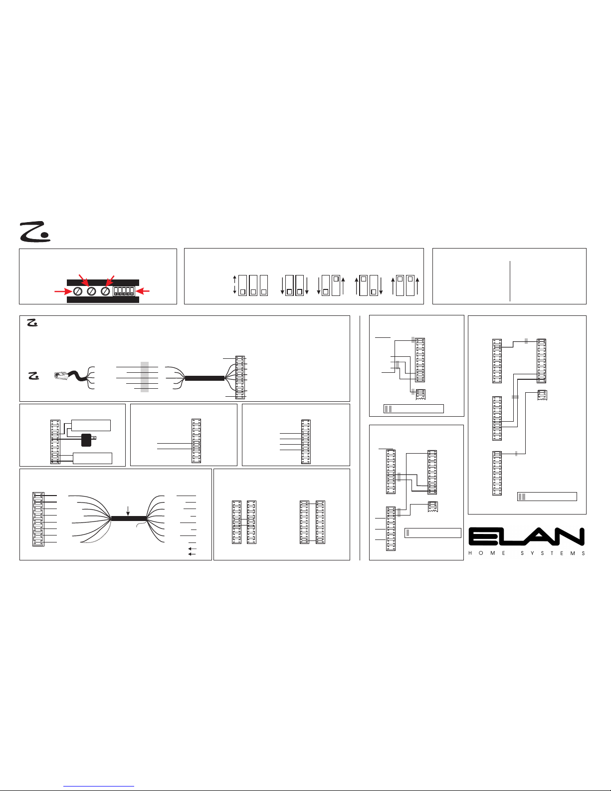
There are six keypad punchdown connectors on the back of the PZ6, labeled Zones 1-6. If using two
PZ6s with 3 or 4 Z630s, the six keypad punchdown connectors would be used for zones 7 thru 12.
Br (GND)
Wh/Gr (+12V)
Gr (485-)
Wh/Or (485+)
Wh/Bl (IR Send)
ELAN
C45P
Br
Wh/Gr
Gr
Wh/Or
Wh/Bl
butt splice
or equivalent
CAT-5
PZ6 Zone
Connector
GND (Brown)
+12V (White/Green)
485- (Green)
485+ (White/Orange)
IR (White/Blue)
PAD
VC- (White/Brown)
VC+ (Orange)
nc
from Z025 VC-
from Z025 VC+
PAD
CONNECTIONS
DOOR SPEAKER ASSEMBLY CONNECTIONS
PZ6 Door
Speaker Connector
Blue
Wh/Blue
Wh/Green
Wh/Orange
Green
Orange
Brown
Wh/Brown
M+
MDBL+
LDB+
DS+
DS-
4 twisted-pair
shielded cable
w/ drain wire
(min. 24 AWG)
(max. length 400')
DRAIN
WIRE
Cut
DRAIN
WIRE
Blue
Wh/Blue
Orange
Wh/Orange
Green
Wh/Green
Brown
Wh/Brown
M+
M DB-
DB+
DS+
DS-
L+
L-
Door
Station
N.O.
COM
to Electronic
Door Latch
RELAY CONNECTIONS
Relay-Controlled
Device
DC
Power
Supply
R1 COM
R1 N.O.
R2 COM
R2 N.O.
R3 COM
R3 N.O.
R4 COM
R4 N.O.
Relay Connector
VCVC+
VCVC+
VCVC+
VCVC+
ELAN Volume
Control w/
Override
VCVC+
VCO Connector
OVERRIDE CONNECTIONS
GND
nc
TIPTELCO
RINGTELCO
TIPPHONE
RINGPHONE
nc
P&DB
Telco Connector
TELCO CONNECTIONS
Telephone
Service IN
to Punch-
down Block
CAT-5
XLINK
ST1
ST2
ST3
ST4
+
-
SIR
GND
IR
PVIA-4
Z485
IR
G
IR
G
IR
G
IR
G
1
2
3
4
= maintain twisted pair
IR1
IR2
IR3
IR4
IR5
IR6
485+
485-
VIA Plate Connector
GND
Telco Connector
PVIA-4 to PZ6
(Zone 1 connections shown)
PVIA-10 to PZ6 (Zone 1 connections shown)
XLINK1
ST1
IR1
ST2
IR2
ST3
IR3
ST4
IR4
GROUND
G
G
G
G
G
G
G
G
XLINK3
ST9
IR9
ST10
IR10
Z485+
Z485 -
SUM IR
SC4 IR
*
*
IR1
IR2
IR3
IR4
IR5
IR6
485+
485-
VIA Plate Connector
GND
Telco Connector
CAT-5
*
*
IR1
IR2
IR3
IR4
IR5
IR6
485+
485-
VIA Plate Connector
PVIA-1
+16V
GND
+16V
GND
V485+
V485IR
ST/SNS
Z485+
Z485SIR
GND
Telco Connector
PVIA-1 to PZ6
(Zone 1 connections shown)
CAT-5
VIA! WALL PLATES to PZ6 CONNECTIONS
SYSTEM QUICK REFERENCE GUIDE
4 5 4 5
Z630 #1
(Zones 1-3)
(factory default)
Z630 #2
(Zones 4-6)
4 5 4 5
Z630 #3
(Zones 7-9)
Z630 #4
(Zones 10-12)
1 2 3
FIXED OUPUT
VARIABLE OUTPUT
(factory default)
ZONES
Z630 DIP SWITCH SETTINGS
Z630 FRONT PANEL ADJUSTMENTS
Music-On-Hold
Output Gain
Page & Door Chime
Sense Level
Page & Door Chime
Input Gain
(Pull back left side of front panel strip to access)
1 2 3 4 5
Dip
Switches
Zone 1: DN DN UP DN
Zone 2: DN DN UP UP
Zone 3: DN UP DN DN
Zone 4: DN UP DN UP
Zone 5: DN UP UP DN
Zone 6: DN UP UP UP
Zone 7: UP DN DN DN
Zone 8: UP DN DN UP
Zone 9: UP DN UP DN
Zone 10: UP DN UP UP
Zone 11: UP UP DN DN
Zone 12: UP UP DN UP
Z100 DIP SWITCH SETTINGS
PZ6 PRECISION PANEL CONNECTIONS
Relay-Controlled
Device
SYSTEM QUICK REFERENCE GUIDE
PZ6 #1
Zone
Connector
GND
+12V
485-
485+
IR
VC-
VC+
nc
GND
+12V
485485+
IR
VC-
VC+
nc
any of the PZ6 Zone
Connectors may be used
PZ6 #2
Zone
Connector
GND
nc
TIPTELCO
RINGTELCO
P&DB
TIPPHONE
RINGPHONE
nc
GND
nc
PZ6 #1
Telco
Connector
TIPTELCO
RINGTELCO
P&DB
TIPPHONE
RINGPHONE
nc
PZ6 #2
Telco
Connector
DUAL PZ6 INTERCONNECTS
= maintain twisted pair
*
= maintain twisted pair
*
Complete Z Series Installation Manuals for each Z Series component are available for download from the ELAN Web Site, www.elanhomesystems.com
(see other side for Z System connections when NOT using a PZ6 Precision Panel)
P/N 40615-148-04 REV: B A p r i l 2 0 03
Page 2

Blue
White/Blue
Orange
White/Orange
Green
White/Green
Brown
White/Brown
White/Brown
Brown
White/Green
Green
White/Orange
Orange
White/Blue
Blue
(- 485)
(+485)
White/Brown
Brown
White/Green
Green
White/Orange
Orange
White/Blue
Blue (Page/DB Control)
Z880
Z600
to
VC-toVC+
on Z025, VSE, VSO, VMO
(MAX 2)
when using Z600
internal power supply
Brown
White/Green
White/Orange
White/Blue
to
VC+
(MAX 30)
when using an external
power supply (Z027)
OR
to
VC-
+
-
Z027
Blue
White/Blue
Orange
White/Orange
Green
White/Green
Brown
White/Brown
White/Brown
Brown
White/Green
Green
White/Orange
Orange
Blue
White/Blue
White/Blue
White/Blue
ZPAD in Zone 1
ZPAD in Zone 2
ZPAD in Zone 3
ZPADs
Optional
Local
IR Emitter
IR
GND
PVIA1, PVIA4
or PVIA10
GND
+16V
485-
485+
VIA IR
VIA IR
VIA IR
X
VIA in Zone 1
VIA in Zone 2
VIA in Zone 3
White/Brown
Brown
White/Green
Green
White/Orange
Orange
Blue
White/Blue
White/Blue
White/Blue
ZPAD in Zone 4
ZPAD in Zone 5
ZPAD in Zone 6
ZPADs
Optional Local
IR Emitter
IR
GND
GND
+16V
485-
485+
VIA IR
VIA IR
VIA IR
X
VIA in Zone 4
VIA in Zone 5
VIA in Zone 6
Z630 #3 (Zones 7-9)
Zone 1 IR Receive
Zone 2 IR Receive
Zone 3 IR Receive
+RS485
-RS485
+12VDC
GND
Page & Doorbell Control
Z630 #1 'IR INPUTS' RJ45 Jack
FUNCTION Pin #
1
2
3
4
5
6
7
8
Color Code
Blue
White/Blue
Orange
White Orange
Green
White/Green
Brown
White/Brown
Zone 4 IR Receive
Zone 5 IR Receive
Zone 6 IR Receive
+RS485
-RS485
+12VDC
GND
Page & Doorbell Control
Z630 #2 'IR INPUTS' RJ45 Jack
FUNCTION Pin #
1
2
3
4
5
6
7
8
Color Code
Blue
White/Blue
Orange
White Orange
Green
White/Green
Brown
White/Brown
Z880
#2
White/Brown
Brown
White/Green
Green
White/Orange
Orange
White/Blue
Blue
(- 485)
(+485)
to Z630
# 3 & 4
to Z630
# 3 & 4
Z630 #4 (Zones 10-12)
SYSTEM CONNECTIONS when NOT Using a PZ6 Precision Panel
BLUE
WHITE/BLUE
ORANGE
WHITE/ORANGE
GREEN
WHITE/GREEN
BROWN
WHITE/BROWN
1
2
3
4
5
6
7
8
PIN # COLOR CODE
FRONT
CABLE
Standard ELAN RJ-45 Pin-Out
(see other side for Z630/Z100 DIp Switch settings & PZ6 Precision Panel connections)
Complete Z Series Installation Manuals for each Z Series component are available for download from the ELAN Web Site, www.elanhomesystems.com
P/N 40615-148-04 A p r i l 2 0 0 3
TAB
(This wiring diagram is for PVIA
Wall Plates ONLY - not for the
direct connection of VIA! Panels
to the Z630.)
PVIA1, PVIA4
or PVIA10
(This wiring diagram is for PVIA
Wall Plates ONLY - not for the
direct connection of VIA! Panels
to the Z630.)
 Loading...