

Elan V85 Installation Manual

V85
Component Video Controller
INSTALLATION MANUAL


E L A N H O M E S Y S T E M S
V85 INSTALLATION MANUAL
Preface
Purpose of This Manual
This manual provides step-by-step installation instructions and connection examples, along with basic user
information for installation and ongoing use of the V85 Component Video Controller. This manual is written for
the installer of this equipment.
Organization
The following information is contained in this manual:
Safety Information
V85 Introduction
V85 System Design
Overview
V85 Connections
Troubleshooting
CVRM Connections
Rack Mounting
Specifications
Provides a comprehensive list of safety practices and procedures allowing for
the safe installation and operation of ELAN Home Systems’ V85 Component Video
Controller.
Provides an introduction to the V85 Component Video Controller, along with system
features to include Front and Rear panel controls, indicators and connections, along
with a short description of each.
Provides a system design application overview of the V85 Component Video
Controller for use in video applications.
Provides a description of V85 Component Video Controller connections including
connections made with ELAN Multi-Room Systems and direct connections to
the V85 Componenet Video Controller from other components.
Provides troubleshooting tables to help fix common discrepancies that may
be associated with the V85 Component Video Controller.
Appendix A provides specifications for connecting the CVRM Component Video
Receive Module to the V85's Cat-5 Video Outputs.
Appendix B provides specifications for Rack Mounting of the V85 Component Video
Controller using the included rack mount brackets.
Appendix C provides equipment specifications for the V85 Component Video
Controller.
© ELAN Home Systems 2009 • All rights reserved. Page I
V85 INSTALLATION MANUAL
CAUTION: TO REDUCE THE RISK OF ELECTRIC SHOCK, DO NOT
REMOVE COVER (OR BACK). NO USER SERVICEABLE PARTS INSIDE.
REFER SERVICING TO QUALIFIED SERVICE PERSONNEL.
CAUTION: RISK OF EXPLOSION IF BATTERY IS REPLACED BY AN
INCORRECT TYPE. DISPOSE OF USED BATTERIES ACCORDING TO
THE INSTRUCTIONS.
The lightning flash with arrowhead symbol within an equilateral triangle is intended to
alert the user to the presence of uninsulated "dangerous voltage" within the product's
enclosure that may be of sufficient magnitude to constitute a risk of electric shock to persons.
The exclamation point within an equilateral triangle is intended to alert the user to the presence
of important operating and maintenance (servicing) instruction in the literature accompanying
the appliance.
WARNING: TO REDUCE THE RISK OF FIRE OR SHOCK,
DO NOT EXPOSE THIS APPLIANCE TO RAIN OR MOISTURE.
WARNING
RISK OF ELECTRIC SHOCK
DO NOT OPEN!
E L A N H O M E S Y S T E M S
CAUTION
IMPORTANT SAFETY INFORMATION
Read Information—All the safety and operating information should be read before the appliance is operated.
Follow Information—All operating and use information should be followed.
Retain Information—The safety and operating information should be retained for future reference.
Heed Warnings—All warnings on the appliance and in the operating instructions should be heeded.
Wall Mounting—Mounting of this appliance should be done only by an authorized installer.
Ventilation—The appliances should be situated so that their location or position does not interfere with their proper ventilation. These appli-
ances should never be placed near or over a radiator or heat register. These appliances should not be placed in a built-in installation such as a
bookcase or cabinet that may impede the flow of air through the ventilation openings.
Non-Use Periods—Appliances that are left unattended and unused for long periods of time should be de-energized.
Power Sources—The appliances should be connected to a power supply only of the type described in the operating instructions or as
marked on each appliance. If you are not sure of the type of power supply to your home, consult your authorized ELAN dealer or local power
company.
Grounding or Polarization—Do not defeat the safety purpose of the polarized or grounding-type plug. A polarized plug has two
blades with one blade wider than the other blade. A grounding type plug has two blades and a third grounding prong. The polarized wide blade
and the third prong are provided for your safety. If the provided plug does not fit your outlet, consult an electrician for replacement of the obsolete
outlet.
Water and Moisture—To reduce the risk of electric shock or fire, these appliances should not be used near water ––for example, near a
bathtub, washbowl, kitchen sink, laundry tub, in a wet basement, or near a swimming pool.
Power Cord Protection—Protect the power cord from being walked on or pinched particularly at plugs, convenience receptacles and
the point where they exit from the apparatus.
Telephones—Avoid using a telephone (other than a cordless type) during an electrical storm. There may be a remote risk of electrical shock
from lightning. Do not use a telephone to report a gas leak if the leak is in the vicinity of the ELAN electronic equipment because of risk of fire or
explosion.
Page II © ELAN Home Systems 2009 • All rights reserved.
E L A N H O M E S Y S T E M S
V85 INSTALLATION MANUAL
Cleaning—Unplug the apparatus from the power outlet before cleaning. Use only a dry cloth to clean the apparatus.
Power Lines—An outdoor antenna should be located away from power lines. When installing an outside antenna system, extreme care
should be taken to avoid touching power lines or circuits, as contact with them may be fatal.
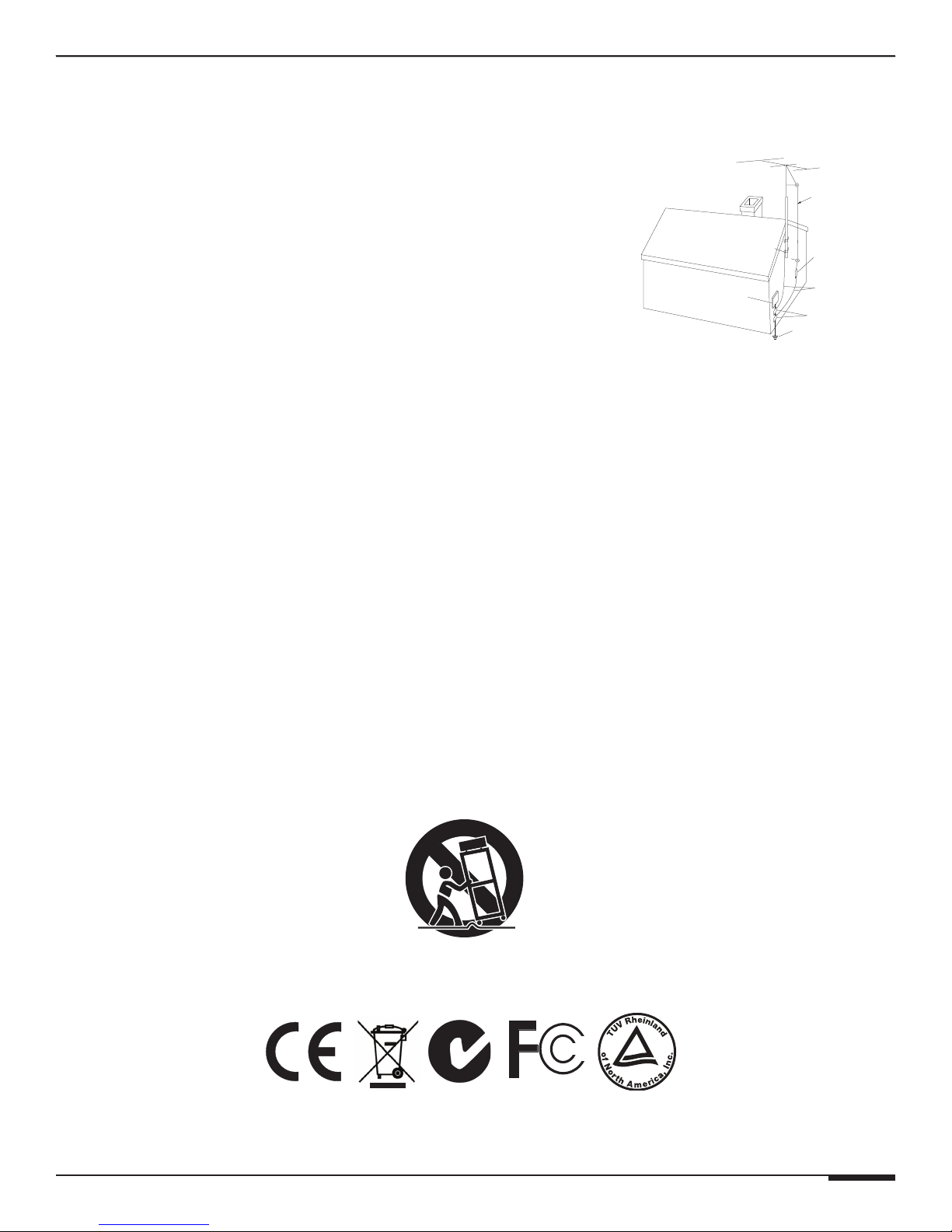
Outdoor Antenna Grounding—If an outside antenna or cable system
is connected to these audio products, be sure the antenna or cable system is grounded
so as to provide some protection against voltage surges and built-up static charges. Section 810 of the U.S. National Electrical Code, and Section 54 of the
Canadian Electrical Code, provide information with respect to proper grounding of
the mast and supporting structure, grounding of the lead-in wire to an antenna
discharge unit, size of grounding conductors, location of antenna-discharge unit,
connection to grounding electrodes, and requirements for the grounding electrode.
See the grounding diagram (right).
Overloading—Do not overload wall outlets and extension cords, as this could
result in fire or electric shock.
Object and Liquid Entry—Never insert objects of any kind through the
openings of these appliances, as they may touch dangerous voltage points or
short-out parts that could result in a fire or electric shock. Care should be taken so that
objects do not fall and liquids are not spilled into the appliance through openings in the enclosure.
Grounding
Diagram
ELECTRIC
SERVICE
EQUIPMENT
NEC - NATIONAL ELECTRICAL CODE
CEC - CANADIAN ELECTRICAL CODE
GROUND
CLAMPS
ANTENNA
LEAD-IN WIRE
ANTENNA LEAD-IN WIRE
(CEC SECTION 54-200)
(NEC SECTION 810-20)
GROUNDING CONDUCTORS
(CEC SECTION 54-200)
(NEC SECTION 810-21)
GROUND CLAMPS
POWER SERVICE GROUNDING
ELECTRODE SYSTEM
(CEC SECTION 10-700)
(NEC ARTICLE 250, PART H)
Servicing—Do not attempt to service these appliances yourself, as opening or removing covers may expose you to dangerous voltage or
other hazards. Refer all servicing to qualified service personnel.
Damage Requiring Service—These appliances should be serviced by qualified service personnel when:
• A power supply connection or a plug has been damaged or
• If liquid has been spilled into the appliance or objects have fallen into the appliance or
• The appliance has been exposed to water or moisture or
• The appliance does not appear to operate normally or exhibits a marked change in performance or
• The appliance has been dropped or the enclosure damaged.
Replacement Parts—When replacement parts are required, be sure the service technician has used replacement parts specified by
the manufacturer or that have the same characteristics as the original part. Unauthorized substitutions may result in fire, electric shock, or other
hazards. The Master Control Unit battery should be replaced only after turning the power off and only by an authorized installer.
Safety Check—Upon completion of any service or repairs to this audio product, ask the service technician to perform safety checks to
determine that the audio product is in proper operating condition.
Lightning Storms—Unplug this apparatus during lightning storms or when unused for long periods of time.
Attachments and Accessories—Use only attachments/accessories specified by the manufacturer.
Cart, Stand, Tripod, Bracket or Table—Use only with a cart, stand, tripod, bracket or table specified by the manufacturer, or
sold with the apparatus. When a cart is used, use caution when moving the cart/apparatus combination to avoid injury from tip over.
Disconnect Device—Where the mains plug or an appliance coupler is used as the disconnect device, the disconnect device shall remain
operable.
C
U S
®
© ELAN Home Systems 2009 • All rights reserved. Page III

V85 INSTALLATION MANUAL
E L A N H O M E S Y S T E M S
Page IV © ELAN Home Systems 2009 • All rights reserved.

E L A N H O M E S Y S T E M S
V85 INSTALLATION MANUAL
Table of Contents
Purpose of This Manual ....................................................................................................................................... I
Organization ............................................................................................................................................................ I
Safety Information ................................................................................................................................................ II
Chapter 1: Introduction
Introduction ............................................................................................................................................................ 1
V85 Features ........................................................................................................................................................... 1
V85 Functions & Indicators .................................................................................................................................. 2
Front Panel .......................................................................................................................................................... 2
Rear Panel .......................................................................................................................................................... 3
Chapter 2: V85 System Design Overview
System Design ...................................................................................................................................................... 4
Pre-Wire .............................................................................................................................................................. 5
Applications ........................................................................................................................................................... 5
Stand-Alone Applications ..................................................................................................................................... 5
Basic Stand-Alone System .................................................................................................................................... 5
Multi-Chassis Stand-Alone System .......................................................................................................................... 6
ELAN Multi-Room Controller-Based Applications .................................................................................................. 7
S66A Application ................................................................................................................................................. 7
S86A or S86P Application ...................................................................................................................................... 8
S128P Application ............................................................................................................................................... 9
Chapter 3: V85 Connections
Component Video Outputs ................................................................................................................................. 10
Cat-5 Video Outputs to CVRM Module ................................................................................................................10
Control Connections - IR .................................................................................................................................... 10
IR IN Port .........................................................................................................................................................11
IR OUT Port ..................................................................................................................................................... 12
Control Connections - RS-232 ............................................................................................................................ 13
RS-232 ............................................................................................................................................................ 13
Multi-Chassis RS-232 ......................................................................................................................................... 13
AC Power Connector ..........................................................................................................................................14
Chapter 4: Operations and Settings
DIP Switch Settings ............................................................................................................................................... 15
Unit ID Settings ................................................................................................................................................. 15
Front Panel ID Designations ................................................................................................................................. 15
BAUD Rate Settings .......................................................................................................................................... 16
IR Power ......................................................................................................................................................... 16
Chapter 5: Programming
Control Methods ................................................................................................................................................... 17
RS232 Command List ............................................................................................................................................ 19
Chapter 6: Troubleshooting ........................................................................................................................................ 21
Appendix A: CVRM Component Video Receive Module .................................................................................... 24
Appendix B: Rack Mounting ................................................................................................................................... 26
Appendix C: Specifications ...................................................................................................................................... 27
Warranty ....................................................................................................................................................... Back Page
© ELAN Home Systems 2009 • All rights reserved. Page V
V85 INSTALLATION MANUAL
E L A N H O M E S Y S T E M S
Items in package:
• V85 Component Video Switcher
• Power Cord
• Installation Manual
• Rack Mount Hardware
V85 Accessories:
• CVRM - Component Video Receive Module
• AVRM - Audio Video Receive Module
• PV12 - Video Precision Panel
Page VI © ELAN Home Systems 2009 • All rights reserved.

E L A N H O M E S Y S T E M S
V85 INSTALLATION MANUAL
Chapter 1: Introduction
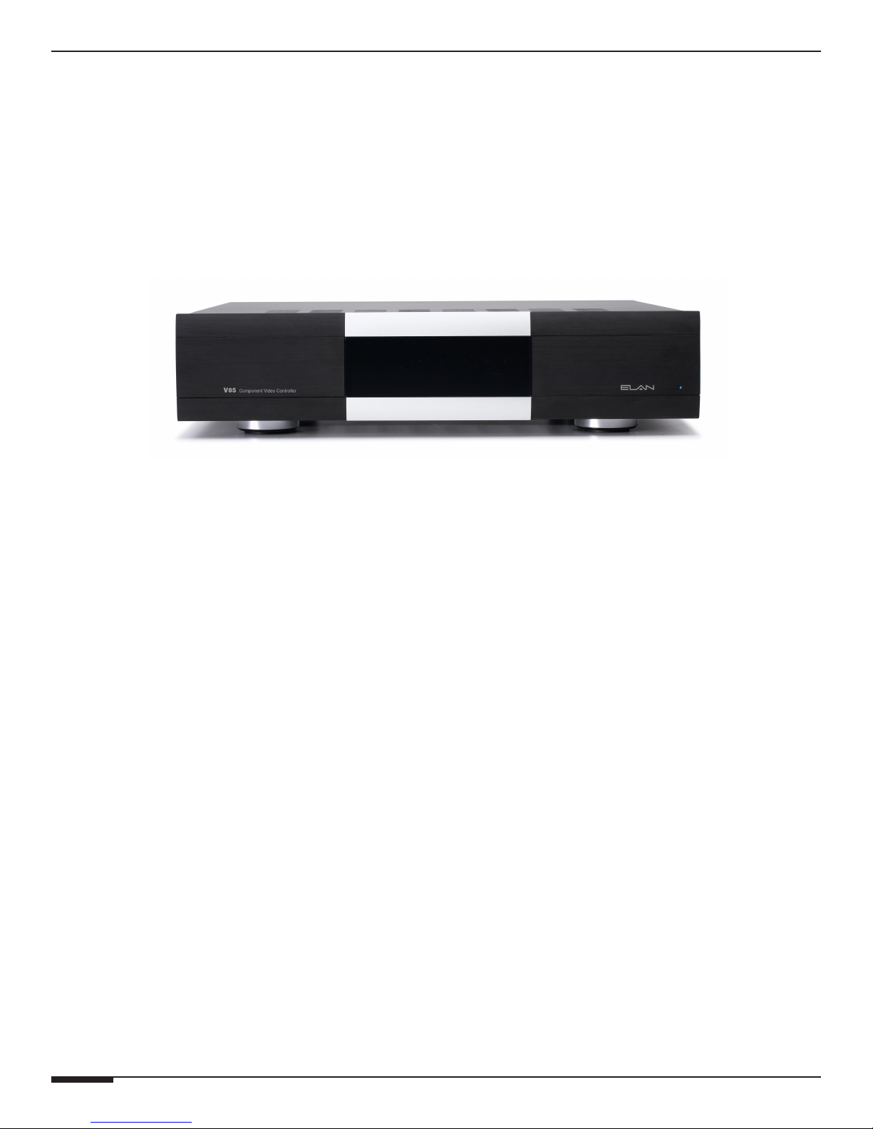
The ELAN V85 Component Video Controller is designed to provide a reliable, affordable solution for multi-room
systems requiring up to eight component video sources to any of eight locations and can be expanded to 32 locations with additional V85 units.
The ELAN Story
Located in Lexington, KY, USA, ELAN Home Systems has designed innovative multi-room audio/video systems
since 1989. ELAN was the first to integrate music, intercom and TV distribution features that used the homeowner's stereos, telephones, and televisions to create the whole-house entertainment experience. These systems allow
people to move freely from room to room, controlling centrally located equipment with ease.
With a current catalog of over 600 items and having been honored with many prestigous industry awards, ELAN is
considered by many to be the leader in whole-house distributed audio/video systems.
V85 Features
• 8 X 8 Component Video Controller with RCA and Cat-5 (RJ-45) video outputs
• Cat-5 video outputs allow for extended wire runs (Up to 500 ft) when using ELAN's
Component Video Receive Modules (CVRM), sold separately
• Component and Cat-5 video outputs can be used simultaneously for 16 total outputs
per chassis*
• Expandable to 8 X 32 with additional V85 units (Or 8 x 64 when using Cat-5 Outputs*)
• RS-232 Controllable
• IR Controllable
Available in 240 Volt Version
cTUVus Certified, CE®, and C-tick
Safety Concerns
Use only grounded outlets when powering this product. Making any modification to the power cord could cause
unsafe operation and will void the manufacturer’s warranty.
* The video of each Cat-5 output mirrors its corresponding component RCA video output. For example, Cat-5
video output 1 will output the same video signal as component video output 1, and so on.
VIA!NET
TO SENSE INPUTSEXT IR
1 2 3
USE STEREO 3.5mm PLUGS ONLY
4 5
ZONE
1
TRIGGERS
2 3 4
1
ZONE
2
5 6 7 8
POWER
ZONE
3
+
ZONE
16VDC / 10A
4
16VDC / 4A
16VDC/1.5A
© ELAN Home Systems 2009 • All rights reserved. Page 1
SS/SC4
ELAN Precision Panels save
6
ZONE
5
ZONE
6
ZONE
7
--
ZONE
8
time and make sense out
®
of complex wiring jobs!
V85 INSTALLATION MANUAL
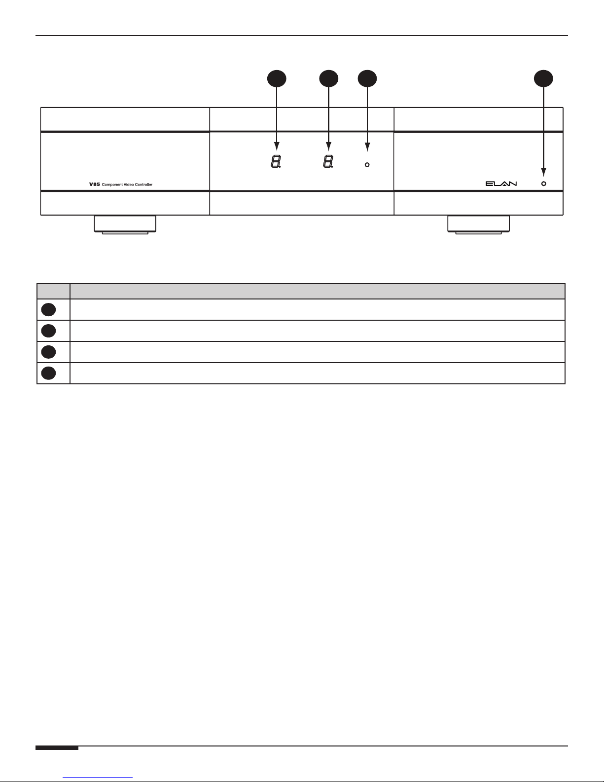
V85 Functions and Indicators
Item Function
OUTPUT CHANNEL INDICATOR
1
1
Figure 1-1: V85 Front Panel
Table 1-1:Front Panel
E L A N H O M E S Y S T E M S
3 42
INPUT CHANNEL INDICATOR
2
IR ACTIVITY LED
3
POWER LED
4
Page 2 © ELAN Home Systems 2009 • All rights reserved.

E L A N H O M E S Y S T E M S
V85 Rear
V85 INSTALLATION MANUAL
1 2
10
Item Function
POWER SWITCH
1
IR IN/OUT
2
RS232 IN/OUT
3
3 4
5
9 8
6
Figure 1-2: V85 Rear Panel
Table 1-2: Rear Panel
7
10
VIA-NET IN/OUT
4
DIP SWITCHES (UNIT ID, BAUD RATE, IR POWER)
5
CAT-5 VIDEO OUTPUTS
6
COMPONENT VIDEO INPUTS
7
COMPONENT VIDEO LOOP OUTPUTS
8
COMPONENT VIDEO ZONE OUTPUTS
9
POWER CORD CONNECTOR/FUSE (REPLACE WITH SPECIFIED TYPE)
© ELAN Home Systems 2009 • All rights reserved. Page 3
 Loading...