

Page 1

INSTALLATION MANUAL
TS10
10” Touch Screen
Page 2

ELAN HOME SYSTEMS TS10 INSTALLATION MANUAL
Preface
Purpose of this Manual
This manual provides step-by-step installation instructions and connection examples, along with basic user information for
installation and ongoing use of the TS10. This manual is written for the installer of this equipment.
Organization
The following information is contained in this manual.
TS10 Introduction
TS10 System Design and
Installation
TS10 System Connections
TS10 Setup and Programming
Troubleshooting
Specifications
Provides an introduction to ELAN Home Systems’ TS10, along with system features including Front
panel controls, and Rear panel connections, along with a short description of each.
Provides a system design application overview and installation requirements for the TS10.
Provides a description of the TS10 system connections and direct connections from the TS10 to other
components.
Provides directions for initial TS10 incorporation into the system.
Provides troubleshooting tables to help fix common problems that may be encountered when
installing the TS10.
Provides equipment specifications for the TS10.
© ELAN Home Systems 2010 | All rights reserved.
Page 1
Page 3

ELAN HOME SYSTEMS TS10 INSTALLATION MANUAL
Table of Contents
Preface ............................................................................................... 1
Purpose of this Manual ................................................................................................. 1
Organization ................................................................................................................. 1
Chapter 1: Introduction ............................................................ 3
The ELAN Story ...................................................................................... 3
TS10 Features ....................................................................................... 4
Applications .......................................................................................... 4
Application Configurations ........................................................................ 5
TS10 Controls and Display ......................................................................... 6
Front Panel Hardware .............................................................................. 7
TS10 Rear Panel Connections ..................................................................... 8
Chapter 2: System Design and Installation ..................................... 9
Planning .............................................................................................. 9
Installation ......................................................................................... 10
Pre-Wire ............................................................................................ 10
Rough-In............................................................................................ 11
Mounting Height .................................................................................. 11
Chapter 3: System Connections ................................................ 12
TS10 to PPSP Connections ...................................................................... 12
Chapter 4: Setup and Programming ........... Error! Bookmark not defined.
Troubleshooting ................................................................................... 14
Specifications ..................................................................................... 15
© ELAN Home Systems 2010 | All rights reserved.
Page 2
Page 4
ELAN HOME SYSTEMS TS10 INSTALLATION MANUAL
Items in Package:
• TS10 Touchscreen
• TS10 White Trim Plate
• TS10 Quick Install Guide
• TS10 Reference Guide
• Ferrite Noise Suppressor
• #6 Wood Screws (x4)
Chapter 1: Introduction
TS10 Touchscreen is a permanently installed, hardwired interface for accessing and
controlling ELAN System Controllers and multiple sub-systems.
The TS10 features a 10” Active Matrix LCD with 800x480 resolution.
Programming for the TS10 resides in the System Controller and is accomplished using
ELAN’s configuration software.
See the ELAN configuration Reference Guide and Integration Notes for programming
and setup information for your specific system components.
The ELAN Story
Located in Lexington, KY, USA, ELAN Home Systems has designed innovative multi-room
audio/video systems since 1989. ELAN systems were the first to integrate music, intercom
and TV distribution features that used the homeowner’s stereos, televisions and telephones
to create the whole-house entertainment experience. These Systems allow people to move
from room to room, controlling centrally located equipment with ease.
ELAN’s product line includes:
• Power Amplifiers
• Multi-Zone Pre-Amps
• Intelligent Keypads
• In-Wall LCD Color Touch Panels
• Wireless LCD Color Touch Panels
• Film Interactive Touchpads
• In-Wall and In-Ceiling Speakers
• Outdoor Speakers
• A/V Controllers
• System Controllers
• Volume Controls
• Telephone-Based Intercom Controllers
• Video Switchers
• Digital Music & DVD Management Systems
• Satellite Radios
• Accessories for Home Systems Installation
© ELAN Home Systems 2010 | All rights reserved.
Page 3
Page 5

ELAN HOME SYSTEMS TS10 INSTALLATION MANUAL
TS10 Features
10” Active Matrix LCD with an 800x480 High Resolution Touchscreen
Composite Video Input and Loop Output
Audible feedback to indicate a button press or system announcement
Programmed using ELAN’s configuration software
Compatible with all current ELAN System Controllers
System and sub-system feedback
Built-in speaker and microphone for messaging features
Screen saver mode that can display photos
Removable bezel with color options (white, ivory, almond, light almond, brown, and black)
Applications
Applications enable control of various sub-systems like Lighting, Security, HVAC, Media,
etc. Pro Apps add features to those that come with the System Controller
For Application configurations see the chart on page five of this manual.
© ELAN Home Systems 2010 | All rights reserved.
Page 4
Page 6

ELAN HOME SYSTEMS TS10 INSTALLATION MANUAL
Unlimited in-home sources
8 Zones
256 Zones
16 Groups (Virtual, for Demo Only)
16 Groups
UPS
Application Configurations
(Subject to change without notice)
Application Included With Controller Added with Pro App
Unlimited ELAN A/V Controllers Unlimited A/V Controllers (any Brand)
Unlimited Sunfire A/V Receivers
Media
Unlimited Display Devices
1 A/V Receiver (any Brand) Unlimited A/V Receivers (any Brand)
Online Audio Content Not Available Online Music Sources
2 Thermostats 32 Thermostats
Climate
History
16 Loads or System Scenes Maximum Loads/Scenes available
Unlimited g! Viewer Keypads
Lighting
Unlimited g! Viewer Scenes
History using Graph Object
1 Partition 8 Partitions
Security
History
IP Camera 2 IP Video Streams 16 IP Video Streams
DVR Not Available Records all Cameras
1 Voicemail Box 8 Voicemail Boxes
Internal Voicemail Internal and Telephone Voicemail
Messaging
Remote Message Retrieval
Remote House Control
Irrigation
256 Zones (Virtual, for Demo Only) 256 Zones
Pool/Spa Virtual (For Demo Only) All Supported Features
Generic Serial Devices
IR Devices
Input/Output Devices
Other
E-Mail
Text-To-Speech
© ELAN Home Systems 2010 | All rights reserved.
Page 5
Page 7

ELAN HOME SYSTEMS TS10 INSTALLATION MANUAL
Panel Controls and Display
9
9
5 4 3 6 7 1 2 3 4
5 6 8
8 2 1
TS10 Controls and Display
Figure 1-1: TS10 Front
Zone Power Toggle / System Off
Press to turn off or on the zone the panel is
in.
Press and hold to turn the system off.
Light Function
Press to access lighting controls.
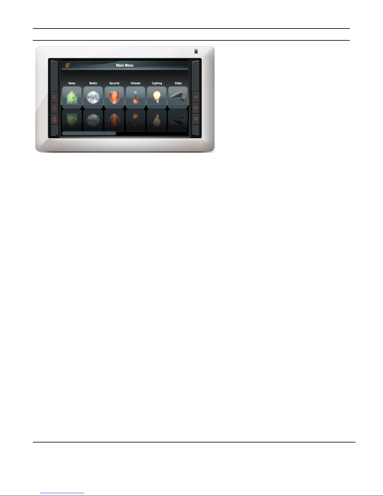
System Information
This area displays system information, i.e. zone
selected, source selection, volume settings, etc.
Information and controls for sub-systems like
HVAC and Security are also displayed here.
Stylus
Volume Up
Sleep Mode
Press to put the TS10 into Sleep Mode, press
and hold to power the TS10 off.
When the TS10 is off, pressing will turn the
panel on.
Press to access the Main Menu Functions
Press to increase the volume in the zone.
Volume Down
Press to decrease the volume in the zone.
Mute Button
Press to mute or un-mute the audio in the zone.
© ELAN Home Systems 2010 | All rights reserved.
Page 6
Page 8

ELAN HOME SYSTEMS TS10 INSTALLATION MANUAL
Front Panel Hardware
Figure 1-2: TS10 Front Panel Hardware
2
1
Mini USB Download Port
(Future firmware upgrades)
3
Speaker
3
2
Microphone
© ELAN Home Systems 2010 | All rights reserved.
Page 7
Page 9

ELAN HOME SYSTEMS TS10 INSTALLATION MANUAL
Ethernet Port
1
2
3
4
TS10 Rear Panel Connections
Figure 1-3: TS10 Rear Panel Connections
5
1
2
Power Connection
16 AWG 2 Conductor
Video Input
F-Connector / RG-6 or RG-59
3
Video Loop Output
F-Connector / RG-6 or RG-59
4
75 Ohm Termination Switch
(Factory Default is TERM)
5
T568A (end to end) or T568B
(end to end)
© ELAN Home Systems 2010 | All rights reserved.
Page 8
Page 10

ELAN HOME SYSTEMS TS10 INSTALLATION MANUAL
Chapter 2: System Design and Installation
Planning
Before installing the TS10, it is essential to have a detailed and accurate system design.
Talk with the homeowner to make sure all expectations and design goals are explored. The
first step to a good design is to map the system. It is advisable to mark up a copy of the
house floor plan with speaker, touchpad, touchscreen, volume control, and equipment
locations etc. Make sure that all locations are decided upon before pre-wiring commences
so that all necessary wiring and installation hardware is in place.
It is essential that ALL system components are accounted for prior to the pre-wire stage.
After establishing design goals with the homeowner, make a detailed list of all components.
Include source equipment, keypads, touchscreens, volume controls, amplifiers,
communications gear, etc. Gather up any IR remote controls that may be necessary for
final programming, or ensure that the IR codes for all equipment to be installed are
available in the ELAN configuration software.
When planning specific in-wall installation locations for LCD touchscreens, please keep the
following tips in mind:
• When properly installed, nothing should be applying contact pressure to the touchscreen
except for the operator’s finger or the stylus. If something is touching the touchscreen
window, a false signal can be generated, causing the touchscreen to respond incorrectly.
• Avoid installation in direct sunlight or strong ultraviolet light (such as grow lamps for
plants). This can degrade and discolor polyester film.
• Avoid installation over heat generating devices and/or in moist areas where condensation
can form on the polyester film. Both heat and condensed moisture can affect touchscreen
performance.
• Avoid installation next to thermostats. The touchscreen generates heat that can affect
thermostat control and readings.
• Avoid applying any foreign objects, such as adhesive labels, glue, etc. to the
touchscreen’s polyester film. This can release chemicals that can discolor the clear film.
• The touchscreen/LCD assembly should not be mounted near electronics that emit radio
frequencies or electromagnetic interference (such as CRT monitors, light dimmers, and
some power supplies).
• Do not mount the TS10 outdoors or in areas exceeding the operating temperature range
of 32° to +104°F (0° to +40°C). If the LCD display is over-heated, or its temperature
reduced below the recommended minimum, the liquid crystal polymer can be damaged
and the display image may not recover.
© ELAN Home Systems 2010 | All rights reserved.
Page 9
Page 11

ELAN HOME SYSTEMS TS10 INSTALLATION MANUAL
Installation
The TS10 is designed to mount into a TS10BKT rough in bracket. The TS10BB back box
can be used in conjunction with the TS10BKT in installations where a back box is desired.
It can also be retrofitted into existing construction. See the TS10BKT and TS10BB
documentation for additional information.
When installing the TS10 in a retrofit application, the cutout dimensions are:
10.75” W X 6.15” H.
273.05 mm W X 156.21 mm H
Pre-Wire
TS10 Touchscreens require power and Ethernet connections to function correctly. Video
connections may also be required.
Control: Cat-5
Power: 2 Conductor (16 AWG)
Video: RG-6 or RG-59 Coaxial Cable
Control / Power
Run Cat-5 and 2 conductor wiring from the main equipment location (head-end) to the
location where the touchscreen will be installed. Make sure that provisions have been made
for installation of a PPSP Power Precision Panel (typically at the headend).
Alternatively, the TS10 can be powered using a PoE adapter. Refer to the PoE Integration
Note for additional details.
Video
TS10 Touchscreens have both a Video Input and a Video Loop Output for composite video
signals. Run RG-6 or RG-59 coaxial cable from the headend location (possibly a video
switcher) to the location where the touch panel will be installed. Be careful not to make
sharp bends when installing coax. F-to-RCA connectors will be necessary to adapt the RCA
composite output of the video source (or switcher) to the F-connector of the coax run. The
TS10s have female F-connectors for both Video Input and Loop Output.
When using the Loop Output to send video signals to another display be sure to set the 75
Ohm termination switch to OPEN.
Note: Maximum wire run is 330 feet (100 meters).
© ELAN Home Systems 2010 | All rights reserved.
Page 10
Page 12

ELAN HOME SYSTEMS TS10 INSTALLATION MANUAL
Rough-In
Roughing-in the TS10 requires careful attention to the design plan made previously. See
System Design & Applications for a list of things to factor in to specific mounting locations
before deciding exactly where to place the unit. In order to avoid Electro-Magnetic
Interference (EMI), do not mount touchscreens close to light dimmers. Leave at least one
stud-bay open between touchscreens and dimmers (leave more space if multiple dimmers
are present). Avoid installing TS10 Touchscreens in areas that will receive direct sunlight.
Do not mount touchscreens outdoors! Corrosion will damage them. ELAN does not
warrant TS10 Touchscreens for outdoor use.
Mounting Height
The TS10 mounting height should be determined by the average height of the user. Typical
mounting height is 56-60 inches (142-152 cm) from the floor to the bottom of the cutout.
This will provide optimum viewing for the largest number of people.
Figure 2-1: TS10 Mounting Height
© ELAN Home Systems 2010 | All rights reserved.
Page 11
Page 13

ELAN HOME SYSTEMS TS10 INSTALLATION MANUAL
Chapter 3: System Connections
TS10 to PPSP Connections
TS10 connection to any of the ELAN Home Controllers (HC12, HC6, etc.) is accomplished
using Ethernet connections. A single Cat5 connects the TS10 to the network. 16 AWG 2
conductor connects to the PPSP Power Precision Panel.
Each PPSP will accommodate connections for up to eight TS10s. The TS10s are powered
by a 16V power supply connected to the PPSP. Each PPSP requires its own 16V power
supply. See the PPSP Quick Install Guide for information regarding power supplies.
The TS10 sends Ethernet messages to the Home Controller. The Home Controller then
issues the proper commands for the sub-system being controlled.
Figure 3-1: TS10 Connections
© ELAN Home Systems 2010 | All rights reserved.
Page 12
Page 14

ELAN HOME SYSTEMS TS10 INSTALLATION MANUAL
Chapter 4: Setup and Programming
The TS10 is automatically added to the system when it is powered up and the Ethernet
connection is made. It will automatically import the DEFAULT touchscreen settings from
the ELAN configuration software.
See the ELAN configuration Reference Guide and Integration Notes for programming
and setup information for your specific system components.
© ELAN Home Systems 2010 | All rights reserved.
Page 13
Page 15

ELAN HOME SYSTEMS TS10 INSTALLATION MANUAL
Troubleshooting
Symptom Possible Cause Solution
TS10 will not power
up.
TS10 powers up but
displays
“Disconnected from
gateway.”
TS10 hard buttons
do not respond.
TS10 video does
not display.
TS10 video displays
but is blurry..
1. Power supply / PPSP connected
incorrectly.
2. Power supply not functioning.
3. AC outlet not functioning.
1. Ethernet connection has an
incorrect pinout.
2. System Controller is not powered
up or is offline.
3. TS10 has been set to a static IP
address that is incompatible.
Trim bezel is not aligned properly. Align trim bezel.
1. Video connection not made or
incorrect.
2. Video switcher not functioning
properly
3. Incorrect commands programmed
for video switcher
75 Ohm termination switch set
incorrectly.
1. Verify power supply / PPSP connections.
2. Verify power supply with a meter.
3. Verify AC outlet with meter. Reset breaker if needed.
1. Verify Cat5 pinout at both ends.
2. Verify System Controller power and Ethernet
connections.
3. Correct static IP address settings or use DHCP settings.
1. Correct connection.
2. Verify video switcher functionality
3. Verify video switcher commands
Set switch correctly
© ELAN Home Systems 2010 | All rights reserved.
Page 14
Page 16

ELAN HOME SYSTEMS TS10 INSTALLATION MANUAL
Video In/Out
“F” Connections
Specifications
Viewing Angle
Operating Temperature 32°F-104°F / 0°C-40°C
Wiring Requirements Cat5, 16-18 AWG 2-wire, RG59 or RG6
Display
Type 10” High Resolution Color LCD Touchscreen
Colors 65K
Resolution 800 pixels (W) x 480 pixels (H)
Connectors
Ethernet Port
Download Port
Power
Power
DC Power Requirements
Current Draw
Dimensions (w/front bezel)
In.
mm.
Dimensions (w/o front bezel)
In.
mm.
Weight (w/o packaging)
lbs.
Kg.
45°up, 55°down, 65° left/right
RJ-45
Mini USB
2-position screw terminal
16VDC
385mA
12.00 W x 7.09 H x 2.58 D
305 W x 180 H x 66 D
11.62 W x 6.81 H x 2.28 D
295 W x 173 H x 58 D
4.1
1.86
Weight (w/packaging)
lbs.
Kg.
© ELAN Home Systems 2010 | All rights reserved.
5.25
2.38
Page 15
Page 17

LIMITED WARRANTY
TS10
ELAN HOME SYSTEMS, L.L.C. (“ELAN”) warrants the HC6/HC12 System Controller
to be free from defects in materials and workmanship for the period of two years (2
years) from date of purchase. If within the applicable warranty period above
purchaser discovers that such item was not as warranted above and promptly
notifies ELAN in writing, ELAN shall repair or replace the item at the company’s
option. This warranty shall not apply (a) to equipment not manufactured by ELAN,
(b) to equipment which shall have been installed by other than an ELAN authorized
installer, (c) to installed equipment which is not installed to ELAN’s specifications,
(d) to equipment which shall have been repaired or altered by others than ELAN,
(e) to equipment which shall have been subjected to negligence, accident, or damage
by circumstances beyond ELAN’s control, including, but not limited to, lightning,
flood, electrical surge, tornado, earthquake, or other catastrophic events beyond
ELAN’s control, or to improper operation, maintenance or storage, or to other than
normal use of service. With respect to equipment sold by, but not manufactured by
ELAN, the warranty obligations of ELAN shall in all respects conform to the warranty
actually extended to ELAN by its supplier. The foregoing warranties do not cover
reimbursement for labor, transportation, removal, installation or other expenses
which may be incurred in connection with repair or replacement. Except as may be
expressly provided and authorized in writing by ELAN, ELAN shall not be subject to
any other obligations or liabilities whatsoever with respect to equipment
manufactured by ELAN or services rendered by ELAN.
THE FOREGOING WARRANTIES ARE EXCLUSIVE AND IN LIEU OF ALL OTHER
EXPRESSED AND IMPLIED WARRANTIES EXCEPT WARRANTIES OF TITLE,
INCLUDING BUT NOT LIMITED TO IMPLIED WARRANTIES OF MERCHANTABILITY
AND FITNESS FOR A PARTICULAR PURPOSE.
ATTENTION: TO OUR VALUED CONSUMERS
To ensure that consumers obtain quality pre-sale and after-sale support and service,
ELAN products are sold exclusively through authorized dealers. ELAN products are
not sold online. The warranties on ELAN products are NOT VALID if the products
have been purchased from an unauthorized dealer or an online E-tailer. To determine
if your ELAN reseller is authorized, please contact ELAN at (859) 269-7760.
www.elanhomesystems.com
P/N 9901146 Rev A
11/03/10
 Loading...