

Page 1

PVSE
INSTALLATION
MANUAL
ELECTRONIC VOLUME CONTROL
PRECISION PANEL
TRIGGERS
12 43
5
6
ALL
IR IN
IR OUT
12 43
5
6
ALL
12 43
5
6
ALL
HOME SYSTEMS
TM
Page 2

Page 3

ELAN HOME SYSTEMS PVSE INSTALLATION MANUAL
© ELAN Home Systems 2005 • All rights reserved. Page 1
Table of Contents
Introduction ........................................................... 2-3
Features .................................................................3
PVSE Front/Rear Panels .......................................4
Installation ............................................................. 4-6
PF2 Precision Panel Frame .................................. 4
Mounting PVSE to PF2 ......................................... 5
Trim-Out .................................................................6
Connections-ELAN System ............................7-21
ELAN System Overview & Wire Runs .................. 7
Rear Panel Connections ................................... 8-18
RJ-45 Pin Out ........................................................8
Punch-Down Connectors ..................................... 8
VSE 1-6 Connections ............................................9
VSE IR OUTPUTS Connections/PS12 ..................10
VSE IR OUTPUTS Connections/S12 .................... 11
VSE IR OUTPUTS Connections/S6 ...................... 12
VSE IR OUTPUTS Connections/PZ6 ....................13
VSE IR OUTPUTS Connections/Z•630 ................ 14
OVERRIDE IN Connections/PZ600 ...................... 15
OVERRIDE OUT Connections/PZ600 ...................16
OVERRIDE IN Connections/PZ6 .......................... 17
OVERRIDE OUT Connections/PZ6 ...................... 17
IR ROUTING Dipswitch Settings .......................... 18
Front Panel Connections .................................. 19-21
TRIGGERS ............................................................. 19
IR IN ....................................................................... 20
IR OUT ................................................................... 21
Connections-Stand-Alone .............................. 22-27
Stand-Alone Overview & Wire Runs .................... 22
Rear Panel Connections ................................... 23-24
VSE 1-6 Connections ............................................23
IR ROUTING Dipswitch Settings .......................... 24
Front Panel Connections .................................. 25-28
TRIGGERS ............................................................. 25
IR IN ....................................................................... 26
IR OUT ................................................................... 27
Power Supply Connections ........................... 28
Warranty ......................................................Back Page
Page 4

PVSE INSTALLATION MANUAL ELAN HOME SYSTEMS
Page 2 © ELAN Home Systems 2005 • All rights reserved.
HOME SYSTEMS
TM
2428 Palumbo Dr.
Lexington, KY USA 40509
Voice 859.269.7760
Tech Support 800-622-3526
Introduction
The PVSE Precision Panel makes it easy to connect up to six ELAN
Electronic Volume Controls (VSE, VSE100, and VEHP) to ELAN S
Series and Z•Series equipment, and is also the perfect trim-out
solution for Electronic Volume Controls in any stand-alone system.
The PVSE is one of ELAN’s 1/2 frame Precision Panels and is
designed to be mounted in a PF2 Precision Panel Frame (see
page 4). Two 1/2 frame Precision Panels can be mounted in one
standard-size Precision Panel Frame, giving the flexibility to mix and
match the Precision Panels needed to complete a neat, problem-free
trim-out.
The back of the PVSE features six clearly labeled 110 punchdown
blocks that provide independent connections for Override, IR, and
Sense; plus two additional connectors for easy routing of Electronic
Volume Control IR signals to the System12 Precision Panel (PS12).
Two RJ-45 jacks on the rear of the panel make it easy to route
Override signals from the PZ600 Communications Controller
Precision Panel and link multiple PVSE panels together. There is
also a bank of six dipswitches that allow you to turn the front panel
volume control-specific IR Out ports into ‘ALL’ ports. In stand-alone
applications, this allows all six Electronic Volume Controls to control
any or all sources.
The PVSE’s front panel was designed with stand-alone applications
in mind. Six Trigger Inputs, plus a Trigger ‘ALL’ port, allow you to
mute any or all Electronic Volume Controls whenever voltage is
not present. Six IR Inputs, plus an ‘ALL’ port, allow a VIA!
®
SR1 or
VIA!®2-SS1 to independently control Electronic Volume Controls
connected to the panel. Six IR Out ports, plus an ‘ALL’ IR Out port,
allow each or all VSEs to control source components in a standalone system.
Electronic Volume Controls that are connected to the PVSE are
powered by the included PWR12 +12VDC/2A power supply.
Page 5
ELAN HOME SYSTEMS PVSE INSTALLATION MANUAL
© ELAN Home Systems 2005 • All rights reserved. Page 3
Introduction (continued)
Features
• 1/2 Frame Precision Panel for Six ELAN Electronic
Volume Controls (VSE, VSE100, and VEHP)
• 110 Punchdown Connectors w/ Clearly Labeled
Silkscreen for Error-Free Terminations
• Easy to Interface with PS12 and PZ600 Precision Panels
• Multiple PVSEs Can Be Linked Together
• Front Panel Trigger and IR In/Out Jacks
for Stand-Alone Applications
• 12VDC, 2A Power Supply Included
• Fits in PF2 Precision Panel Frame
(required for installation)
• Punchdown Tool & Caps Included
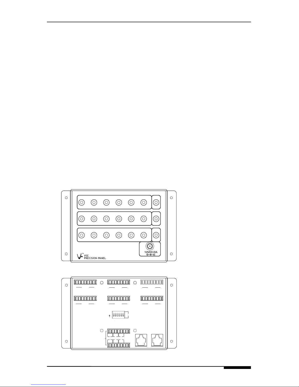
PVSE Front/Rear Panels
• TRIGGERS (Inputs)
Connects to Triggering Device
• IR IN
Connects to IR Source
• 12VDC/2A
Connects to PWR12 Power Supply
• IR OUT
Connects to Source to be Controlled
• VSE 1-6
Connects to ELAN Electronic Volume
Controls (VSE, VSE100, VEHP)
• IR ROUTING Dipswitches
Controls IR OUT IR Routing
• VSE IR OUTPUTS
Connects to ELAN Multi-Zone
Controllers
• OVERRIDE OUT
Connects to additional PVSE
• OVERRIDE IN
Connects from a PZ600, Z•600,
or additional PVSE
TRIGGERS
12 43
5
6
ALL
IR IN
IR OUT
12 43
5
6
ALL
12 43
5
6
ALL
SENSEGV+NC NCIROVCO
IRI
SENSENC V+ GIROVCO
IRI
NC
VSE 2 VSE
3
VSE 5
VSE 4
VSE 6
SENSEGV+NCNC
IRI
IROVCOSENSEIROVCO NC
IRI
NC V+ VCO NC
IRI
IRO V+NC SENSE
GGIRG
IR
G
IR
GGGG
VSE IR
OUTPUTS
OVERRIDE
OUT
OVERRIDE
IN
12
3
4
5
GG
IR
6
IR
ALL
12
3456
IR ROUTING
IR
SENSENC V+ GIROVCO
IRI
NC
VSE
1
GG
Front
Rear
Page 6

PVSE INSTALLATION MANUAL ELAN HOME SYSTEMS
Page 4 © ELAN Home Systems 2005 • All rights reserved.
Installation
PF2 Precision Panel Frame
The PF2 accommodates any two 1/2 frame Precision Panels.
The kit includes a full-size Precision Panel frame, an insert with predrilled holes for the mounting of two 1/2 frame Precision Panels,
mounting screws, and a blank 1/2 frame plate to cover an unused
half of the frame. PBKT6P new-construction brackets are available,
or the PF2 can easily be retro-fitted using the four clamping legs
attached to the frame, which clamp the panel securely to drywall.
Note: The PF2 is required for the installation of all 1/2 frame
Precision Panels.
Page 7
ELAN HOME SYSTEMS PVSE INSTALLATION MANUAL
© ELAN Home Systems 2005 • All rights reserved. Page 5
Installation (continued)
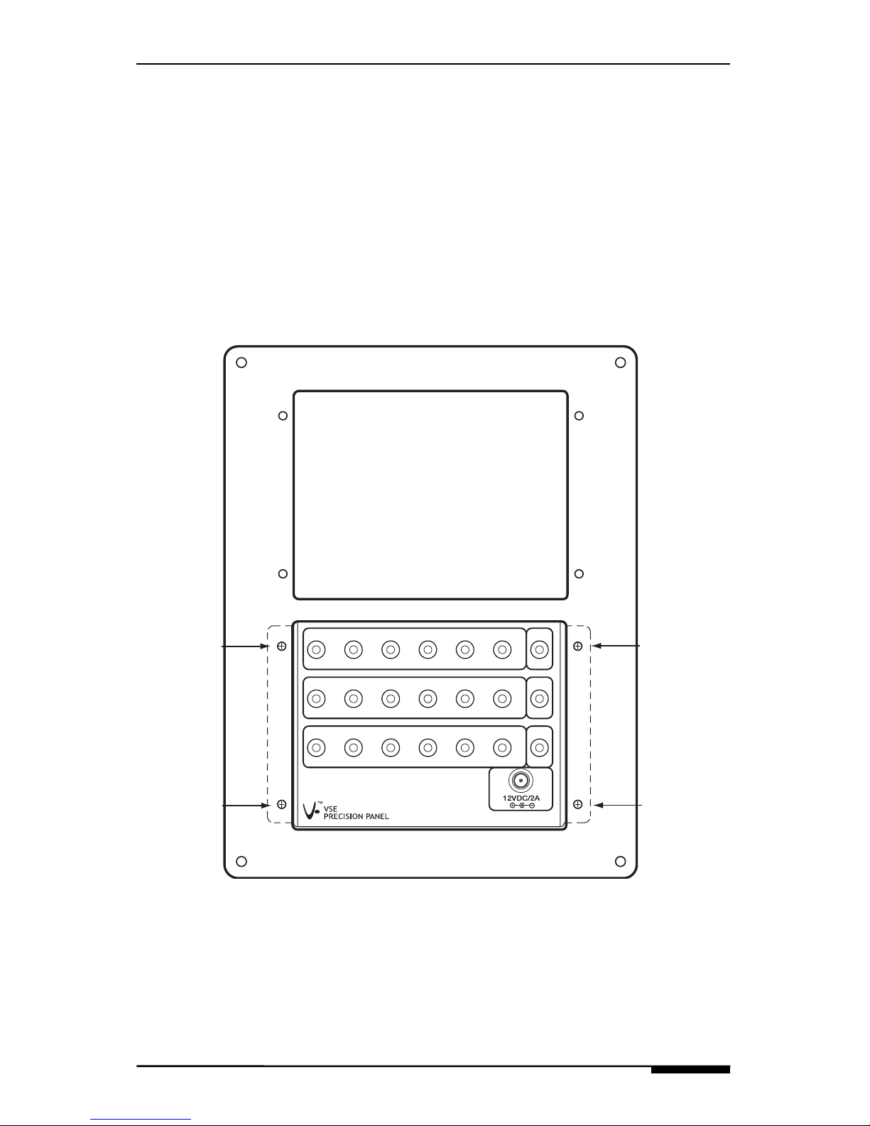
Mounting the PVSE to the PF2
Each 1/2 frame Precision Panel mounts from the back of the PF2.
Use four included screws inserted from the front of the PF2 as
shown below.
Screw
Screw
Screw
Screw
PF2 Front
Front
TRIGGERS
12 43
5
6
ALL
IR IN
IR OUT
12 43
5
6
ALL
12 43
5
6
ALL
Page 8

PVSE INSTALLATION MANUAL ELAN HOME SYSTEMS
Page 6 © ELAN Home Systems 2005 • All rights reserved.
Installation (continued)
Trim-Out
All system wire runs are pulled through the PF2 frame. Lay the PVSE
front panel (attached to the PF2) on the floor in front of the frame
and make all connections. Dress the wires in neat bundles, being
careful not to pull off any punchdown connections, and then carefully
place the PVSE/PF2 back into the frame and secure using the four
screws.
Wire Runs
Page 9
ELAN HOME SYSTEMS PVSE INSTALLATION MANUAL
© ELAN Home Systems 2005 • All rights reserved. Page 7
Connections-ELAN System
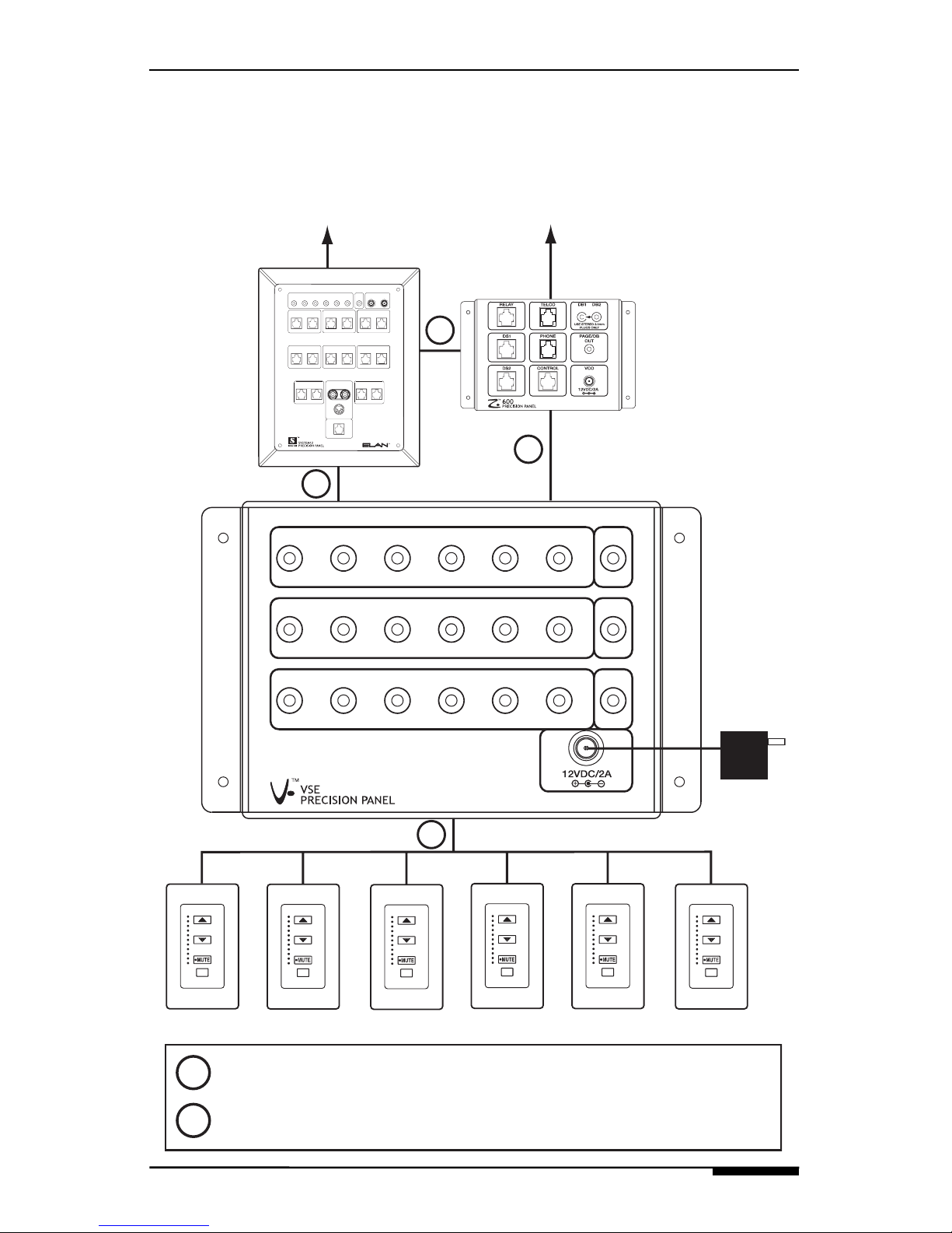
PVSE ELAN System Overview and Wire Runs
XM FM
12
3456
+
--
1
ZONE1LOCAL
22
ZONE LOCAL
33
ZONE LOCAL
4
ZONE4LOCAL
55
ZONE LOCAL6ZONE6LOCAL
8
LOCAL8ZONE
7
LOCAL7ZONE VIA!POWER
16VDC / 10A
16VDC / 4A
VIA!NET
TO SENSE INPUTS
USE STEREO 3.5mm PLUGS ONLY
EXTIR
ANTENNA
+12VDC
Power
Supply
PS12
PZ600
V
SE/VEHP
PWR12
(included)
TRIGGERS
12 43
5
6
ALL
IR IN
IR OUT
12 43
5
6
ALL
12 43
5
6
ALL
VSE/VEHP
VSE/VEHP
VSE/VEHP
VSE/VEHP
VSE/VEHP
To Z•600
To S12
1
1
1
2
1
Cat-5
2
ELAN C4545 RJ-45 Interconnect Cable
Page 10
PVSE INSTALLATION MANUAL ELAN HOME SYSTEMS
Page 8 © ELAN Home Systems 2005 • All rights reserved.
ELAN System Connections (continued)
Rear Panel Connections
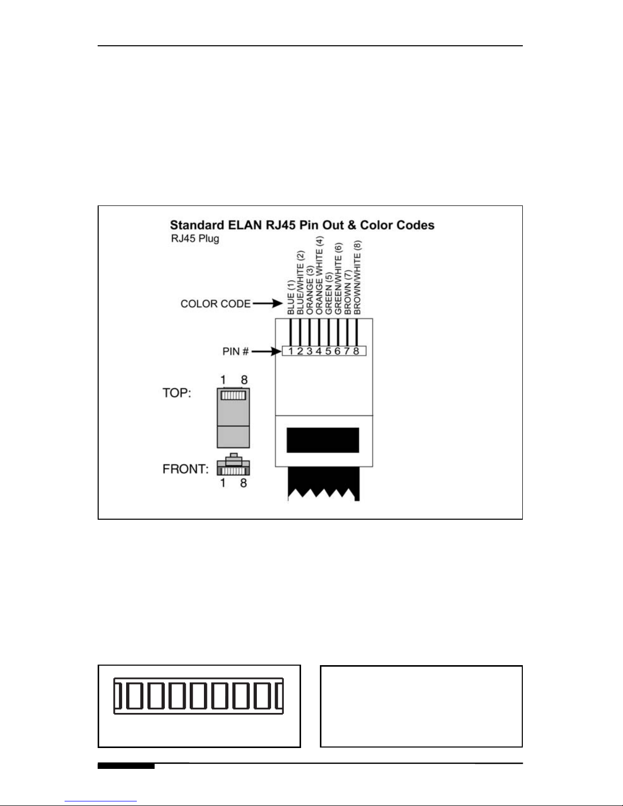
RJ-45 Pin Out
ELAN recommends using ELAN C4545 and/or C45P RJ-45 interconnect cables for all Cat-5 connections to the PVSE. Should you prefer
to terminate your own RJ45 cables, refer to the diagram below for
the correct pin-out.
PVSE Punch-Down Connectors
The back of the PVSE uses standard 110 punchdown connectors for
all wire runs. Wires do not need to be stripped prior to punchdown
as the insulation will automatically be displaced. Each punchdown
row will accept two 24 or 22 AWG solid conductor wires. Use the
included 110 punchdown tool to properly make connections and
avoid damaging the PVSE.
110 Punch-Down Connecto
r
NOTE:
The PVSE comes with punchdown caps to ensure that
connections won’t come loose.
Page 11

ELAN HOME SYSTEMS PVSE INSTALLATION MANUAL
© ELAN Home Systems 2005 • All rights reserved. Page 9
ELAN System Connections-Rear (continued)
VSE 1-6 Connections
Punch-down each wire according to ELAN standard pin-out
(previous page). Be sure to note which Electronic Volume Control
is punched-down to each connector. The diagram below shows
VSE’s #1 through #3 properly connected.
SENSEGV+NC NCIROVCO
IRI
SENSENC V+ GIROVCO
IRI
NC
VSE 2 VSE
3
VSE 5
VSE 4
VSE 6
SENSEGV+NCNC
IRI
IROVCOSENSEIROVCO NC
IRI
NC V+ VCO NC
IRI
IRO V+NC SENSE
GG
IRGIR
G
IR
GGGG
VSE IR
OUTPUTS
OVERRIDE
OUT
OVERRIDE
IN
12
3
4
5
GG
IR
6
IR
ALL
12
3456
IR ROUTING
IR
SENSENC V+ GIROVCO
IRI
NC
VSE
1
GG
VSE/VEHP #3
Blue
Wh/Blue
Orange
Wh/Orange
Green
Wh/Green
Brown
Wh/Brown
VSE/VEHP #2
Blue
Wh/Blue
Orange
Wh/Orange
Green
Wh/Green
Brown
Wh/Brown
VSE/VEHP #1
Blue
Wh/Blue
Orange
Wh/Orange
Green
Wh/Green
Brown
Wh/Brown
Page 12

PVSE INSTALLATION MANUAL ELAN HOME SYSTEMS
Page 10 © ELAN Home Systems 2005 • All rights reserved.
ELAN System Connections-Rear (continued)
VSE IR OUTPUTS Connections to PS12
The VSE IR OUTPUTS are designed to route IR from a specific
Electronic Volume Control to a specific zone of an S6, S12,
or Z•system. When installing an S12 system, ELAN strongly
recommends the use of the PS12 Precision Panel! To route IR to
a specific S12 zone, use a run of Cat-5 to connect IR and Ground
from VSE IR OUTPUTS on the PVSE to ADDITIONAL IR INPUTS
on the PS12. Make sure to connect the correct VSE IR OUTPUT on
the PVSE to the correct ADDITIONAL IR INPUT on the PS12. The
diagram below shows VSE #1 connected to S12 Zone 1.
SENSEGV+NC NCIROVCO
IRI
SENSENC V+ GIROVCO
IRI
NC
VSE 2 VSE3
VSE 5
VSE
6
VSE
4
SENSEGV+NCNC
IRI
IROVCOSENSEIROVCO NC
IRI
NC V+ VCO NC
IRI
IRO V+NC SENSE
GG
IRGIR
G
IR
GGGG
VSE IR
OUTPUTS
OVERRIDE
OUT
OVERRIDE
IN
12
3
4
5
GG
IR
6
IR
ALL
12
3456
IR ROUTING
IR
PVSE
ADDITIONAL IR INPUTS
IRIR
G
1
IR
G
2G3
IR
G
4
PS12
G
G
SENSENC V+ GIROVCO
IRI
NC
VSE
1
Page 13

ELAN HOME SYSTEMS PVSE INSTALLATION MANUAL
© ELAN Home Systems 2005 • All rights reserved. Page 11
ELAN System Connections-Rear (continued)
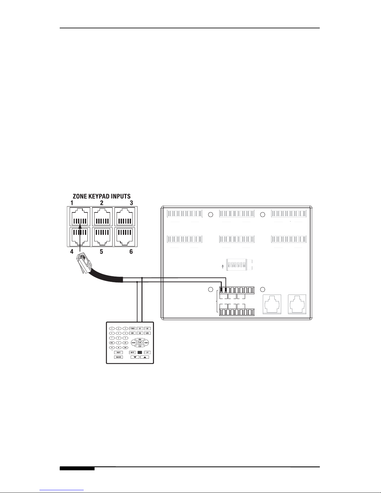
VSE IR OUTPUTS Connections to S12 (no PS12)
If not using a PS12 to install an S12 system, it is necessary to
connect two conductors of a Cat-5 wire from the PVSE’s VSE IR
OUTPUTS to the ZONE KEYPAD INPUTS of the S12. Connect
IR from the PVSE to the Wh/Blue IR Input wire (PIN 2) of the S12.
Connect G from the PVSE to Brown (Pin 7) of the S12. Make these
connections in parallel with any keypads or touch panels that are in
the same zone as the Electronic Volume Control. Make sure to connect the correct VSE IR OUTPUT of the PVSE to the correct ZONE
KEYPAD INPUT of the S12. The diagram below shows VSE #1 to
S12 Zone 1 connections. Only the keypad’s IR and Ground are
shown for clarity.
SENSEGV+NC NCIROVCO
IRI
SENSENC V+ GIROVCO
IRI
NC
VSE 2 VSE3
VSE 5
VSE
6
VSE
4
SENSEGV+NCNC
IRI
IROVCOSENSEIROVCO NC
IRI
NC V+ VCO NC
IRI
IRO V+NC SENSE
GG
IRGIR
G
IR
GGGG
VSE IR
OUTPUTS
OVERRIDE
OUT
OVERRIDE
IN
12
3
4
5
GG
IR
6
IR
ALL
12
3456
IR ROUTING
IR
PVSE
G
G
SENSENC V+ GIROVCO
IRI
NC
VSE
1
S12
ELAN C45P RJ-45
interconnect cable
White/Blue (IR)
Brown (GND)
Keypad
Brown (GND)
White/Blue (IR)
Page 14
PVSE INSTALLATION MANUAL ELAN HOME SYSTEMS
Page 12 © ELAN Home Systems 2005 • All rights reserved.
ELAN System Connections-Rear (continued)
VSE IR OUTPUTS Connections to S6
When installing a PVSE into an ELAN S6 system, connect two
conductors of a Cat-5 wire from the VSE IR OUTPUTS to the
ZONE KEYPAD INPUTS of the S6. Connect IR from the PVSE to
the Wh/Blue IR Input wire (PIN 2) of the S6. Connect G from the
PVSE to Brown (Pin 7) of the S6. Make these connections in parallel
with any keypads or touch panels that are in the same zone as the
Electronic Volume Control. Make sure to connect the correct VSE IR
OUTPUT of the PVSE to the correct ZONE KEYPAD INPUT of the
S6. The diagram below shows VSE #1 to S6 Zone 1 connections.
Only the keypad’s IR and Ground are shown for clarity.
SENSEGV+NC NCIROVCO
IRI
SENSENC V+ GIROVCO
IRI
NC
VSE 2 VSE3
VSE 5
VSE
6
VSE
4
SENSEGV+NCNC
IRI
IROVCOSENSEIROVCO NC
IRI
NC V+ VCO NC
IRI
IRO V+NC SENSE
GG
IRGIR
G
IR
GGGG
VSE IR
OUTPUTS
OVERRIDE
OUT
OVERRIDE
IN
12
3
4
5
GG
IR
6
IR
ALL
123456
IR ROUTING
IR
PVSE
G
G
SENSENC V+ GIROVCO
IRI
NC
VSE
1
ELAN C45P RJ-45
interconnect cable
White/Blue (IR)
Brown (GND)
S6
Keypad
Brown (GND)
White/Blue (IR)
Page 15

ELAN HOME SYSTEMS PVSE INSTALLATION MANUAL
© ELAN Home Systems 2005 • All rights reserved. Page 13
ELAN System Connections-Rear (continued)
VSE IR OUTPUTS Connections to PZ6
When installing an ELAN Z system, the PVSE will route IR from a
specific Electronic Volume Control to a specific Z•system zone.
Panel! To route IR to a specific Z•630 zone, use a run of Cat-5 to
connect IR and Ground from VSE IR OUTPUTS on the PVSE to
ZONE punch-down locations on a PZ6 Precision Panel. Make sure
to connect the correct VSE IR OUTPUT on the PVSE to the correct
ZONE punchdown location on the PZ6. The diagram below shows
VSE #1 to ZONE 1 connections.
SENSEGV+NC NCIROVCO
IRI
SENSENC V+ GIROVCO
IRI
NC
VSE 2 VSE3
VSE 5
VSE
6
VSE
4
SENSEGV+NCNC
IRI
IROVCOSENSEIROVCO NC
IRI
NC V+ VCO NC
IRI
IRO V+NC SENSE
GG
IRGIR
G
IR
GGGG
VSE IR
OUTPUTS
OVERRIDE
OUT
OVERRIDE
IN
12
3
4
5
GG
IR
6
IR
ALL
12
3456
IR ROUTING
IR
PVSE
G
G
SENSENC V+ GIROVCO
IRI
NC
VSE
1
Br
Wh/G
r
Gr
Wh/O
r
Wh/Bl
nc
Or
Wh/B
r
PZ6
Page 16

PVSE INSTALLATION MANUAL ELAN HOME SYSTEMS
Page 14 © ELAN Home Systems 2005 • All rights reserved.
ELAN System Connections-Rear (continued)
VSE IR OUTPUTS Connections to Z•630 (no PZ6)
If not using a PZ6 to install a Z• system, it is necessary to connect
two conductors of a Cat-5 wire from the PVSE’s VSE IR OUTPUTS
to the IR INPUTS of the Z•630. Connect IR from the PVSE to the
IR INPUTS wire of the specific zone of the Z•630 that the Electronic
Volume Control will be assigned to . Connect G from the PVSE to
Brown (Pin 7) of the Z•630. Make these connections in parallel with
any keypads or touch panels that are in the same zone as the
Electronic Volume Control. The diagram below shows VSE #1 con-
nected to Zone #2 of a Z•630. Only the keypad’s IR and Ground
connections are shown for clarity. See the Z
•630 Installation
Manual for complete details about IR INPUT wiring of a Z• system.
IR
INPUTS
Z•630
SENSEGV+NC NCIROVCO
IRI
SENSENC V+ GIROVCO
IRI
NC
VSE 2 VSE3
VSE 5
VSE
6
VSE
4
SENSEGV+NCNC
IRI
IROVCOSENSEIROVCO NC
IRI
NC V+ VCO NC
IRI
IRO V+NC SENSE
GG
IRGIR
G
IR
GGGG
VSE IR
OUTPUTS
OVERRIDE
OUT
OVERRIDE
IN
12
3
4
5
GG
IR
6
IR
ALL
12
3456
IR ROUTING
IR
PVSE
G
G
SENSENC V+ GIROVCO
IRI
NC
VSE
1
ELAN C45P RJ-45
interconnect cable
White/Blue (IR)
Brown (GND)
Keypad
Brown (GND)
White/Blue (IR)
Zone 2 Shown
Page 17

ELAN HOME SYSTEMS PVSE INSTALLATION MANUAL
© ELAN Home Systems 2005 • All rights reserved. Page 15
ELAN System Connections-Rear (continued)
OVERRIDE IN Connections w/ PZ600
The OVERRIDE IN RJ-45 jack is designed to take the Volume
Control Override signal from a Z•600 Communications Controller
and automatically route it to the VC+ and VC- connections on
Electronic Volume Controls connected to the PVSE. Use of a PZ600
Precision Panel is highly recommended when installing a PVSE in an
ELAN S6 or S12 system that includes a Z•600. Connect an ELAN
C4545 RJ-45 patch cable from the Z•600’s CONTROL OUTPUTS
jack to the OVERRIDE IN RJ-45 jack on the PZ600, then connect an
additional C4545 from the PZ600’s OVERRIDE OUT jack to
OVERRIDE IN of the PVSE as shown below.
VCO
COM
N.O.
COM
N.O.
COM
N.O.
COM
N.O.
W/Bl
Br
W/Br
W/Or
W/Gr
Gr
Or
Bl
RELAY DS1
M-
DS+
DS-
L+
L-
DB-
DB+
M+
L+
DS-
DS+
L-
DB-
M-
DB+
M+
DS2
W/Or
W/Br
Br
W/Gr
Gr
W/Bl
Or
Bl
TELCO
RNG
nc
nc
nc
nc
TIP
TIP
RNG
VCO
4
3
21
PHONE
TELCO
OVERRIDE
OUT
VC+
VC-
VC-
VC+
VC+
VC-
VC-
VC+
VC-
VC-
VC+
VC+
VC+
VC-
VC+
VC-
OVERRIDE
IN
PZ600 Rear
ELAN C4545 RJ-45
interconnect cable
SENSEGV+NC NCIROVCO
IRI
SENSENC V+ GIROVCO
IRI
NC
VSE 2
VSE 3
VSE 5
VSE 6
VSE 4
SENSEGV+NCNC
IRI
IROVCOSENSEIROVCO NC
IRI
NC V+ VCO NC
IRI
IRO V+NC SENSE
GG
IRGIR
G
IR
GGGG
VSE IR
OUTPUTS
OVERRIDE
OUT
OVERRIDE
IN
12
3
4
5
GG
IR
6
IR
ALL
12
3456
IR ROUTING
IR
SENSENC V+ GIROVCO
IRI
NC
VSE 1
ELAN C4545 RJ-45
interconnect cable
PVSE Rear
G
G
Page 18

PVSE INSTALLATION MANUAL ELAN HOME SYSTEMS
Page 16 © ELAN Home Systems 2005 • All rights reserved.
ELAN System Connections-Rear (continued)
OVERRIDE OUT Connections w/ PZ600
The OVERRIDE OUT RJ-45 jack is designed for system expansion.
When connecting multiple PVSE’s, connect the OVERRIDE OUT
RJ-45 jack from PVSE #1 to the OVERRIDE IN RJ-45 jack on PVSE
#2. Continue the process for all PVSEs in the system. The diagram
below shows a Z•600 connected to a PZ600, then to two PVSEs.
VCO
COM
N.O.
COM
N.O.
COM
N.O.
COM
N.O.
W/Bl
Br
W/Br
W/Or
W/Gr
Gr
Or
Bl
RELAY DS1
M-
DS+
DS-
L+
L-
DB-
DB+
M+
L+
DS-
DS+
L-
DB-
M-
DB+
M+
DS2
W/Or
W/Br
Br
W/Gr
Gr
W/Bl
Or
Bl
TELCO
RNG
nc
nc
nc
nc
TIP
TIP
RNG
VCO
4
3
21
PHONE
TELCO
OVERRIDE
OUT
VC+
VC-
VC-
VC+
VC+
VC-
VC-
VC+
VC-
VC-
VC+
VC+
VC+
VC-
VC+
VC-
OVERRIDE
IN
PZ600 Rear
ELAN C4545 RJ-45
interconnect cable
SENSEGV+NC NCIROVCO
IRI
SENSENC V+ GIROVCO
IRI
NC
VSE 2
VSE 3
VSE 5
VSE 6
VSE 4
SENSEGV+NCNC
IRI
IROVCOSENSEIROVCO NC
IRI
NC V+ VCO NC
IRI
IRO V+NC SENSE
GGIRG
IR
GIRGGGG
VSE IR
OUTPUTS
OVERRIDE
OUT
OVERRIDE
IN
12
3
4
5
GG
IR
6
IR
ALL
12
3456
IR ROUTING
IR
SENSENC V+ GIROVCO
IRI
NC
VSE 1
PVSE #1 Rear
G
G
SENSEGV+NC NCIROVCO
IRI
SENSENC V+ GIROVCO
IRI
NC
VSE 2VSE 3
VSE 5
VSE 6
VSE 4
SENSEGV+NCNC
IRI
IROVCOSENSEIROVCO NC
IRI
NC V+ VCO NC
IRI
IRO V+NC SENSE
GGIRG
IR
GIRGGGG
VSE IR
OUTPUTS
OVERRIDE
OUT
OVERRIDE
IN
12
3
4
5
GG
IR
6
IR
ALL
12
3456
IR ROUTING
IR
SENSENC V+ GIROVCO
IRI
NC
VSE 1
PVSE #2 Rear
G
G
ELAN C4545 RJ-45
interconnect cable
To additional PVSEs
Page 19

ELAN HOME SYSTEMS PVSE INSTALLATION MANUAL
© ELAN Home Systems 2005 • All rights reserved. Page 17
ELAN System Connections-Rear (continued)
OVERRIDE IN Connections w/ PZ6
If using the PVSE witha PZ6 Precision Panel for Z• Systems, it is
necessary to use an ELAN C45P RJ-45 to pigtail cable to connect
VC+ and VC- from the back of the PZ6 to theOVERRIDE IN RJ-45
jack on the back of the PVSE as shown below. Pin 1 (Blue) of the
RJ-45 cable is VC+, Pin 2 (Wh/Blue) is VC-.
OVERRIDE OUT Connections w/ PZ6
OVERRIDE OUT connections will go to additional PVSEs exactly as
shown on p. 16.
ELAN C45P
RJ-45 to
pigtail cable
OVERRIDE
IN
Blue
Wh/Blue
OVERRIDE
OUT
PZ6
PVSE
Page 20

PVSE INSTALLATION MANUAL ELAN HOME SYSTEMS
Page 18 © ELAN Home Systems 2005 • All rights reserved.
ELAN System Connections-Rear (continued)
IR ROUTING Dipswitch Settings
IR from Electronic Volume Controls connected to the PVSE can be
routed to the front IR Output jacks in two different ways. By default,
the dipswitches are all down, meaning that each Electronic Volume
Control sends IR to its’ specific IR port on the front of the panel, and
the ALL port. For example, the Electronic Volume Control connected
to the VSE 1 location will only send IR out of IR OUT 1 and ALL.
By moving a dipswitch to the upper ALL position, the corresponding
IR OUT port becomes an ALL port; passing IR signals from every
Electronic Volume Control that is connected to the PVSE.
The original ALL port remains active and functions identically
regardless of dipswitch settings.
In the example below, Dipswitch #1 is in the Up position. IR OUT
#1 will pass IR sent from any Electronic Volume Control that is connected to the PVSE. Dipswitch #2 is in the Down position. IR OUT
#2 will only pass IR from the Electronic Volume Control connected to
the VSE 2 location. The ALL port will pass IR from both volume
controls.
ALL
12
3456
IR ROUTING
TRIGGERS
12 43
5
6
ALL
IR IN
IR OUT
12 43
5
6
ALL
12 43
5
6
ALL
Emits IR from any
Volume Control
Emits IR from
Volume Control #2
Emits IR from any
Volume Control
Page 21

ELAN HOME SYSTEMS PVSE INSTALLATION MANUAL
© ELAN Home Systems 2005 • All rights reserved. Page 19
ELAN System Connections (continued)
Front Panel Connections
TRIGGERS
ELAN Electronic Volume Controls have a feature called “Sense”
which corresponds to the TRIGGERS ports on the PVSE and provides the ability to Mute when voltage is absent. Connect a mono
3.5mm interconnect cable from a specific TRIGGERS port on the
PVSE to a ZONE TRIGGER OUTPUT or UNIT TRIG OUT of a
System12, a ZONE TRIGGER OUTPUT or SYSTEM TRIG OUT of
an S6, the REMOTE OUT of a Z•POWER, Z•630 or Z•660 amplfier,
or the +12VDC TRIGGER OUT of a D1200 or D1650 amplifier, in
order to Mute the Electronic Volume Controls when a specific zone is
turned Off. Connect the Trigger output to the ALL TRIGGERS port
to Mute all volume controls simultaneously. The Electronic Volume
Controls will not automatically Un-Mute when the zone or system is
turned back On. See the VSE Electronic Volume Control
Installation Manual for valuable information about how Electronic
Volume Controls’ Sense features react to Triggers.
TRIGGERS
12 43
5
6
ALL
IR IN
IR OUT
12 43
5
6
ALL
12 43
5
6
ALL
S12
D1650
mono 3.5mm
interconnect
cables
Page 22

PVSE INSTALLATION MANUAL ELAN HOME SYSTEMS
Page 20 © ELAN Home Systems 2005 • All rights reserved.
ELAN System Connections (continued)
IR IN
Use the IR IN ports to control specific volume controls from an
ELAN IR source such as a VIA!
®
SR1 or VIA!®2-SS1. Connect a
mono 3.5mm interconnect cable from an IR source’s IR output port
to the IR IN port of the PVSE. Make sure to connect the correct out-
put to the correct input! Connecting an IR source to the IR IN ALL
port will send IR to all volume controls connected to the PVSE.
The drawing below shows a VIA!SR1 connected to a PVSE Precision
Panel. The SR1’s IR OUTPUT 1-3 ports are each assigned to a
specific IR IN port on the PVSE. SR1 IR OUTPUT #1 will send IR to
the volume control connected to VSE1 on the PVSE, IR OUTPUT #2
sends IR to VSE 2, etc. SR1 IR OUTPUT #8 sends IR to the IR IN
ALL port and will control all volume controls connected to the PVSE.
TRIGGERS
12 43
5
6
ALL
IR IN
IR OUT
12 43
5
6
ALL
12 43
5
6
ALL
SENSE INPUTS
IR OUTPUTS
PWR
IR
SENSE/RELAY MODULE
SR-1
PVSE
VIA!SR1
mono 3.5mm
interconnect
cables
Page 23

ELAN HOME SYSTEMS PVSE INSTALLATION MANUAL
© ELAN Home Systems 2005 • All rights reserved. Page 21
ELAN System Connections (continued)
IR OUT
The IR OUT ports route IR that originates at the volume control loca-
tion (typically a hand-held remote). Punch-downs are located on
the rear of the PVSE that deal with IR routing for most ELAN system
applications, therefore, the front panel IR OUT ports are seldom
used in an ELAN system. One System12 application does present
itself, though. Use a specific IR OUT port or the ALL port to connect
to the EXT IR IN port of an S12. This will allow IR to pass-through
Electronic Volume Controls that are not part of an S12 zone to control source equipment that is part of the S12 system.
The diagram below shows IR OUT #1 from the PVSE connected to
the EXT IR IN port on the System12. The volume control connected
to VSE 1 can send IR to sources connected to the S12.
TRIGGERS
12 43
5
6
ALL
IR IN
IR OUT
12 43
5
6
ALL
12 43
5
6
ALL
PVSE
S12
mono 3.5mm
interconnect
cable
Page 24

PVSE INSTALLATION MANUAL ELAN HOME SYSTEMS
Page 22 © ELAN Home Systems 2005 • All rights reserved.
Connections-Stand-Alone
PVSE Stand-Alone Overview and Wire Runs
+12VDC
Power
Supply
PWR12
(included)
TRIGGERS
12 43
5
6
ALL
IR IN
IR OUT
12 43
5
6
ALL
12 43
5
6
ALL
DVD
SAT
CD
VSE/VEHP
VSE/VEHP
VSE/VEHP
VSE/VEHP
VSE/VEHP
VSE/VEHP
IR
Receiver
IR
Connecting
Block
1
1
2
2
3
3
+12V
GND
ST OUT
IR IN
IR
RCVR
STATUS IN
5~24V DC
12V DC
REGULATED
HP ON
HP ON
NET ON
LP ON
LP ON
LP IR OUT
NET OFF
IRD4
Amplified Connection Block
LP/HP IR OUT
+12VDC
Power
Supply
1
Cat-5
2
Mono 3.5mm Interconnect Cable
3
IR Emitter
Page 25

ELAN HOME SYSTEMS PVSE INSTALLATION MANUAL
© ELAN Home Systems 2005 • All rights reserved. Page 23
Stand-Alone Connections-Rear
VSE 1-6 Connections
Punch-down each wire according to ELAN standard pin-out
(p. 8). Be sure to note which Electronic Volume Control is
punched-down to each connector. The diagram below shows
VSE’s #1 through #3 properly connected.
SENSEGV+NC NCIROVCO
IRI
SENSENC V+ GIROVCO
IRI
NC
VSE 2 VSE
3
VSE 5
VSE 4
VSE 6
SENSEGV+NCNC
IRI
IROVCOSENSEIROVCO NC
IRI
NC V+ VCO NC
IRI
IRO V+NC SENSE
GG
IRGIR
G
IR
GGGG
VSE IR
OUTPUTS
OVERRIDE
OUT
OVERRIDE
IN
12
3
4
5
GG
IR
6
IR
ALL
12
3456
IR ROUTING
IR
SENSENC V+ GIROVCO
IRI
NC
VSE
1
GG
VSE/VEHP #3
Blue
Wh/Blue
Orange
Wh/Orange
Green
Wh/Green
Brown
Wh/Brown
VSE/VEHP #2
Blue
Wh/Blue
Orange
Wh/Orange
Green
Wh/Green
Brown
Wh/Brown
VSE/VEHP #1
Blue
Wh/Blue
Orange
Wh/Orange
Green
Wh/Green
Brown
Wh/Brown
Page 26

PVSE INSTALLATION MANUAL ELAN HOME SYSTEMS
Page 24 © ELAN Home Systems 2005 • All rights reserved.
Stand-Alone Connections-Rear (continued)
IR ROUTING Dipswitch Settings
IR from Electronic Volume Controls connected to the PVSE can be
routed to the front IR Output jacks in two different ways. By default,
the dipswitches are all down, meaning that each Electronic Volume
Control sends IR to its’ specific IR port on the front of the panel and
the ALL port. For example, the Electronic Volume Control connected
to the VSE 1 location will only send IR out of IR OUT 1 and ALL.
By moving a dipswitch to the upper ALL position, the corresponding
IR OUT port becomes an ALL port; passing IR signals from every
Electronic Volume Control that is connected to the PVSE.
The original ALL port remains active and functions identically
regardless of dipswitch settings.
In the example below, Dipswitch #1 is in the Up position. IR OUT
#1 will pass IR sent from any Electronic Volume Control that is connected to the PVSE. Dipswitch #2 is in the Down position. IR OUT
#2 will only pass IR from the Electronic Volume Control connected to
the VSE 2 location. The ALL port will pass IR from both volume
controls.
ALL
12
3456
IR ROUTING
TRIGGERS
12 43
5
6
ALL
IR IN
IR OUT
12 43
5
6
ALL
12 43
5
6
ALL
Emits IR from any
Volume Control
Emits IR from
Volume Control #2
Emits IR from any
Volume Control
Page 27

ELAN HOME SYSTEMS PVSE INSTALLATION MANUAL
© ELAN Home Systems 2005 • All rights reserved. Page 25
Stand-Alone Connections-Front
TRIGGERS Connections
The TRIGGERS ports on the PVSE act as inputs. Although normally
used for ELAN system integration, the TRIGGERS ports on the front
of the PVSE can be used to activate the “Sense” feature of Electronic
Volume Controls in Stand-Alone applications.
Connect a mono 3.5mm plug into the TRIGGERS jack that corresponds to the Electronic Volume Control that is to be Muted. If all
the volume controls are to Mute together, connect this plug into the
ALL port. Connect the other end to a source that provides 3-24 VDC
output when turned On. Certain amplifiers and A/V or Stereo
Receivers have triggered outputs.
The diagram below shows an A/V Receiver muting the volume
control connected to VSE 1, while an Amplifier Mutes all volume
controls connected to the PVSE.
TRIGGERS
12 43
5
6
ALL
IR IN
IR OUT
12 43
5
6
ALL
12 43
5
6
ALL
mono 3.5mm
interconnect
cables
A/V Receiver Amplifier
Page 28

PVSE INSTALLATION MANUAL ELAN HOME SYSTEMS
Page 26 © ELAN Home Systems 2005 • All rights reserved.
Stand-Alone Connections-Front (continued)
IR IN Connections
It is possible to send IR to ELAN Electronic Volume Controls through
the IR IN ports on the front of the PVSE. The volume control will
respond to signals it receives just like it would if a hand-held IR
remote control were pointed at it. Connect an IR receiver or other
IR source such as an IR connecting block to the specific IR IN port
that corresponds with the volume control you are sending the IR to.
If volume control-specific IR functionality is not required, connect the
IR source to the ALL port.
The example below shows an IR Receiver/IR Connecting Block
connected to IR IN #1. IR sent to this IR Receiver will be routed to
the volume control that is connected to the VSE 1 punchdown
location. Also shown is a VIA!
®
Touch Panel that is connected to the
ALL port, which will route IR to all volume controls connected to the
PVSE.
TRIGGERS
12 43
5
6
ALL
IR IN
IR OUT
12 43
5
6
ALL
12 43
5
6
ALL
PVSE
VALET
PWR
IR
OUT
VIDEO IN
Z CUBE
PVIA1
VIA!Valet
mono
3.5mm
interconnect
cable
IR
Receiver
IR
Connecting
Block
+12V
GND
ST OUT
IR IN
IR
RCVR
STATUS IN
5~24V DC
12V DC
REGULATED
HP ON
HP ON
NET ON
LP ON
LP ON
LP IR OUT
NET OFF
IRD4
Amplified Connection Block
LP/HP IR OUT
+12VDC
Power
Supply
mono
3.5mm
interconnect
cable
Page 29

ELAN HOME SYSTEMS PVSE INSTALLATION MANUAL
© ELAN Home Systems 2005 • All rights reserved. Page 27
Stand-Alone Connections-Front (continued)
IR OUT Connections
See IR ROUTING Dipswitch Settings (p. 24) before making
IR OUT connections. Once the configuration is decided upon
and the IR ROUTING dipswitches are correctly set, plug IR miniemitters or mono 3.5mm interconnect cables into the appropriate
IR OUT ports.
The diagram below shows IR OUT #1 connected to a DVD player.
IR ROUTING Dipswitch #1 is in the Down position so that the DVD
player can only be controlled from the volume control that is
punched down to the VSE 1 location on the back of the PVSE.
An A/V Receiver is connected to the ALL port and can be controlled
by any volume control connected to the PVSE. IR ROUTING
Dipswitch #2 is in the Up position. IR OUT #2 sends IR from
any volume control connected to the PVSE to the Satellite Receiver
connected to IR OUT #2.
ALL
12
3456
IR ROUTING
TRIGGERS
12 43
5
6
ALL
IR IN
IR OUT
12 43
5
6
ALL
12 43
5
6
ALL
DVD
SAT
A/V Receiver
Page 30

PVSE INSTALLATION MANUAL ELAN HOME SYSTEMS
Page 28 © ELAN Home Systems 2005 • All rights reserved.
Power Supply Connections
12VDC/1.5A
The PWR3 power supply that is included with the PVSE is designed
to power up to six ELAN Electronic Volume Controls. Connect the
power supply to the front of the PVSE as shown below.
TRIGGERS
12 43
5
6
ALL
IR OUT
12 43
5
6
ALL
PVSE
IR IN
12 43
5
6
ALL
+12VDC
Power
Supply
PWR12
(included)
Page 31

ELAN HOME SYSTEMS PVSE INSTALLATION MANUAL
© ELAN Home Systems 2005 • All rights reserved. Page 29
ELAN 1/2 Frame Precision Panels
ELAN’s new 1/2 frame Precision Panels save time and make sense
out of complex wiring tasks. Add reliability and simplicity to your
installs by using them in every job!
PZ600
The PZ600 Precision Panel
allows the connection of phone
service, page, Doorbell and
Override signals, relays and
door stations to the Z•600
Communications Controller and
ELAN S Series controllers.
PV8
The PV8 Video Precision Panel
provides a clean and easy way
to connect up to 8 runs of
coaxial cable to the System12
A/V Controller or Z•880 Video
Controller.
PSP6
The PSP6 Speaker Precision
Panel is a neat and easy way
to connect in-wall wire runs
from up to six pairs of speakers
(twelve speakers total) to a
system’s amplifier.
PF2
The PF2 Precision Panel Frame
accomodates any two 1/2 frame
Precision panels (PZ600, PVSE,
PV8, & PSP6). This kit includes
a full-sized Precision panel
frame, a blank 1/2 frame plate
to cover any unused half of the
frame, and all mounting hardware. Required for use with all
1/2 frame Precision Panels.
RELAY
TELCO
DS1 PHONE
DS2
CONTROL
VCO
PAGE/DB
OUT
DB1 DB2
Z600
PRECISION
PANEL
+
--
+
--
+
--
+
--
+
--
+
--
Page 32

ELAN HOME SYSTEMS L.L.C. ("ELAN") warrants the PVSE Precision Panel
to be free from defects in materials and workmanship for the period of
two years (2 years) from date of purchase. If within the applicable warranty
period above purchaser discovers that such item was not as warranted
above and promptly notifies ELAN in writing, ELAN shall repair or replace
the item at the company's option. This warranty shall not apply (a) to
equipment not manufactured by ELAN, (b) to equipment which shall have
been installed by other than an ELAN authorized installer, (c) to installed
equipment which is not installed to ELAN's specifications, (d) to equipment
which shall have been repaired or altered by others than ELAN, (e) to
equipment which shall have been subjected to negligence, accident, or
damage by circumstances beyond ELAN's control, including, but not limited
to, lightning, flood, electrical surge, tornado, earthquake, or other
catastrophic events beyond ELAN's control, or to improper operation,
maintenance or storage, or to other than normal use of service. With
respect to equipment sold by, but not manufactured by ELAN, the warranty
obligations of ELAN shall in all respects conform to the warranty actually
extended to ELAN by its supplier. The foregoing warranties do not cover
reimbursement for labor, transportation, removal, installation or other
expenses which may be incurred in connection with repair or replacement.
Except as may be expressly provided and authorized in writing by ELAN,
ELAN shall not be subject to any other obligations or liabilities whatsoever
with respect to equipment manufactured by ELAN or services rendered by
ELAN.
THE FOREGOING WARRANTIES ARE EXCLUSIVE AND IN LIEU OF ALL
OTHER EXPRESSED AND IMPLIED WARRANTIES EXCEPT WARRANTIES
OF TITLE, INCLUDING BUT NOT LIMITED TO IMPLIED WARRANTIES OF
MERCHANTABILITY AND FITNESS FOR A PARTICULAR PURPOSE.
ATTENTION: TO OUR VALUED CONSUMERS
To ensure that consumers obtain quality pre-sale and after-sale
support and service, ELAN Home Systems products are sold
exclusively through authorized dealers. ELAN products are not sold
online. The warranties on ELAN products are NOT VALID if the
products have been purchased from an unauthorized dealer or an
online E-tailer. To determine if your ELAN reseller is authorized,
please call ELAN Home Systems at (859) 269-7760.
Limited Warranty
2428 Palumbo Drive Lexington, KY 40509
www.elanhomesystems.com
P/N 9900562 REV: B
 Loading...