

ELAN EM91455DK, EM91455CK, EM91455BP, EM91455AP Datasheet
GENERAL DESCRIPTION
The EM91455 is a series of tone/pulse switchable dialers that is composed of T/P dialer and T/P dialer with
3 sets memories. The EM91455 provide modern LCD driver's series data output port, which can display modern
function operating icons. The EM91455 series provide necessary functions of telephone set for application in
any environment, such as Pulse dialing, Tone (DTMF) dialing, Handfree dialing, keying tone ,and lock functions.
The lock function is designed to inhibit toll dialing operation. Beside this, ring detector and SDO (Serial Data
Output) functions are provided in advance version. Ring detector can prevent illegal dialing from pocket dialer.
The SDO is designed to drive LCD driver and voice synthesizer. In this application, the dialing numbers and
modern function operating icons can be displayed on LCD screen with LCD driver (EM32100 or EM32117 ).
The EM91455 has a special I.P.P. detect function (Illegal Parallel Phone Detect) can prevent the illegal connect
external Phone. The I.P.P. will detect the illegal user. When illegal user pickup phone, the function will alarm
and send the alarm signal to the telephone line to interfer the illegal dialing.
EM91455 SERIES
TONE/PULSE DIALER WITH LCD INTERFACE
AND I.P.P. DETECT FUNCTION
FEATURES
• I.P.P. detect function prevents the illegal connect external phone.
• SDO function supports LCD driver and voice synthesizer to indicate dialing numbers and function
operating icons.
• Lock function provides conventionality key lock and password lock operations.
• Ring detector is designed to prevent illegal dialing from pocket dialer.
• Line hold function is designed for stopping conversation temporality.
• Tone/Pulse switchable.
• Wide operating voltage from 2.0 V to 5.5 V.
• Low operating current, 0.15 mA (Pulse) and 0.3 mA (Tone) typically.
• Adding resistor on keyboard scan pin that can select many telephone specifications, such as : Pulse rate,
M/B ratio, Flash time, lock dialing functions.
• 3-set one touch repertory memory, each one can hold data up to 16 digits.
• A 32-digit LNB (last number) redial memory.
• Keytone function provides rapidly keying recognition.
• Handfree function provides on-hook dialing and speakerphone application.
• Pause and P-T time are fixed to 3.6 seconds.
• Tone duration and inter-tone pause time are fixed to 98 ms.
• Using 3.579545 MHz crystal or ceramic resonator.
• Package forms: PDIP, skinny.
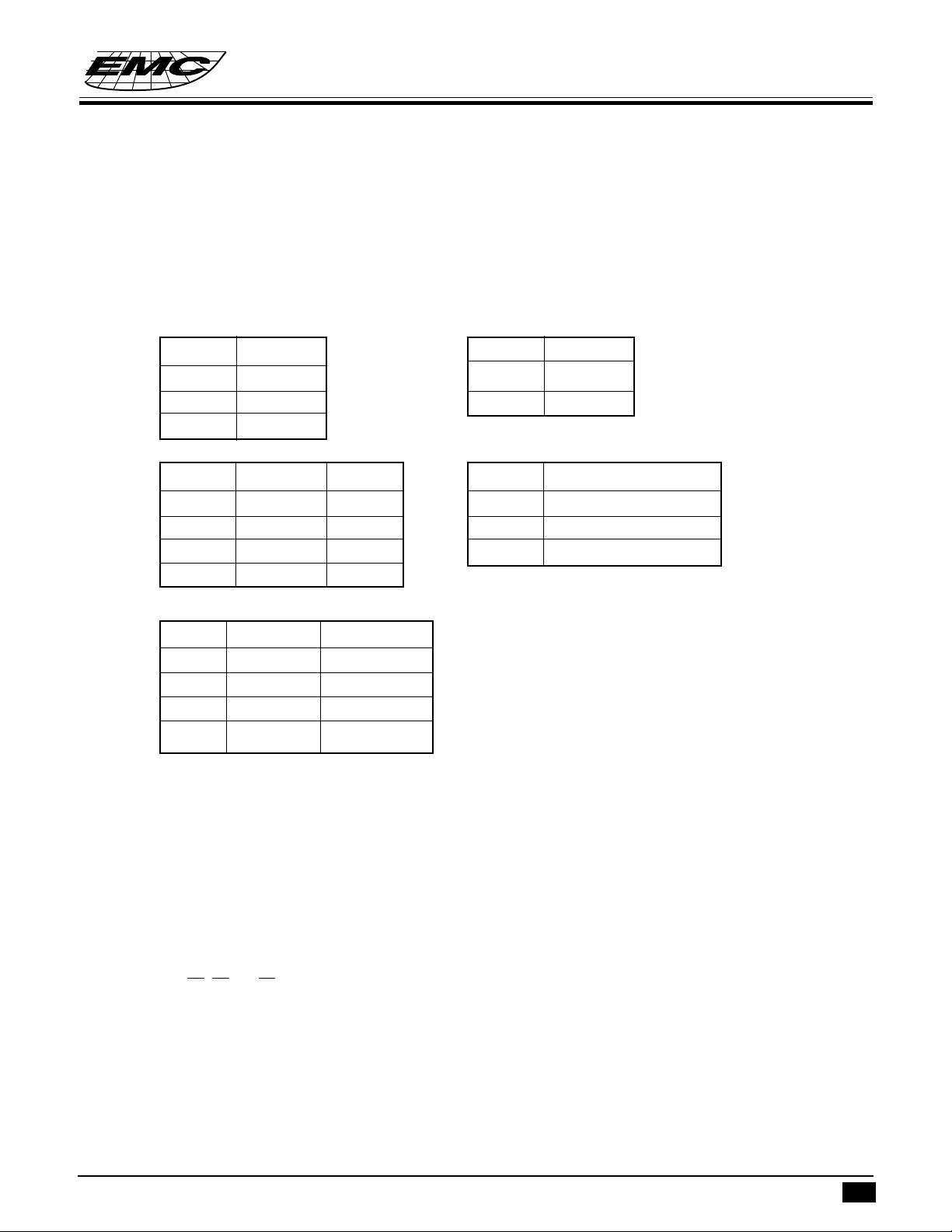
ORDERING INFORMATION
Versions list and function outline
VERSION LNB KT HOLD I.P.P. LOCK HF SDO(LCD) PDP
EM91455A √√√√√
EM91455B √√√√√√
EM91455C √√√√√√√
EM91455D √√√√√√√√
Note : PDP = Pocket Dialer Prevented
: I.P.P. detect = Illegal Parallel Phone Detect.
* This specification are subject to be changed without notice.
9.24.1998
1
EM91455
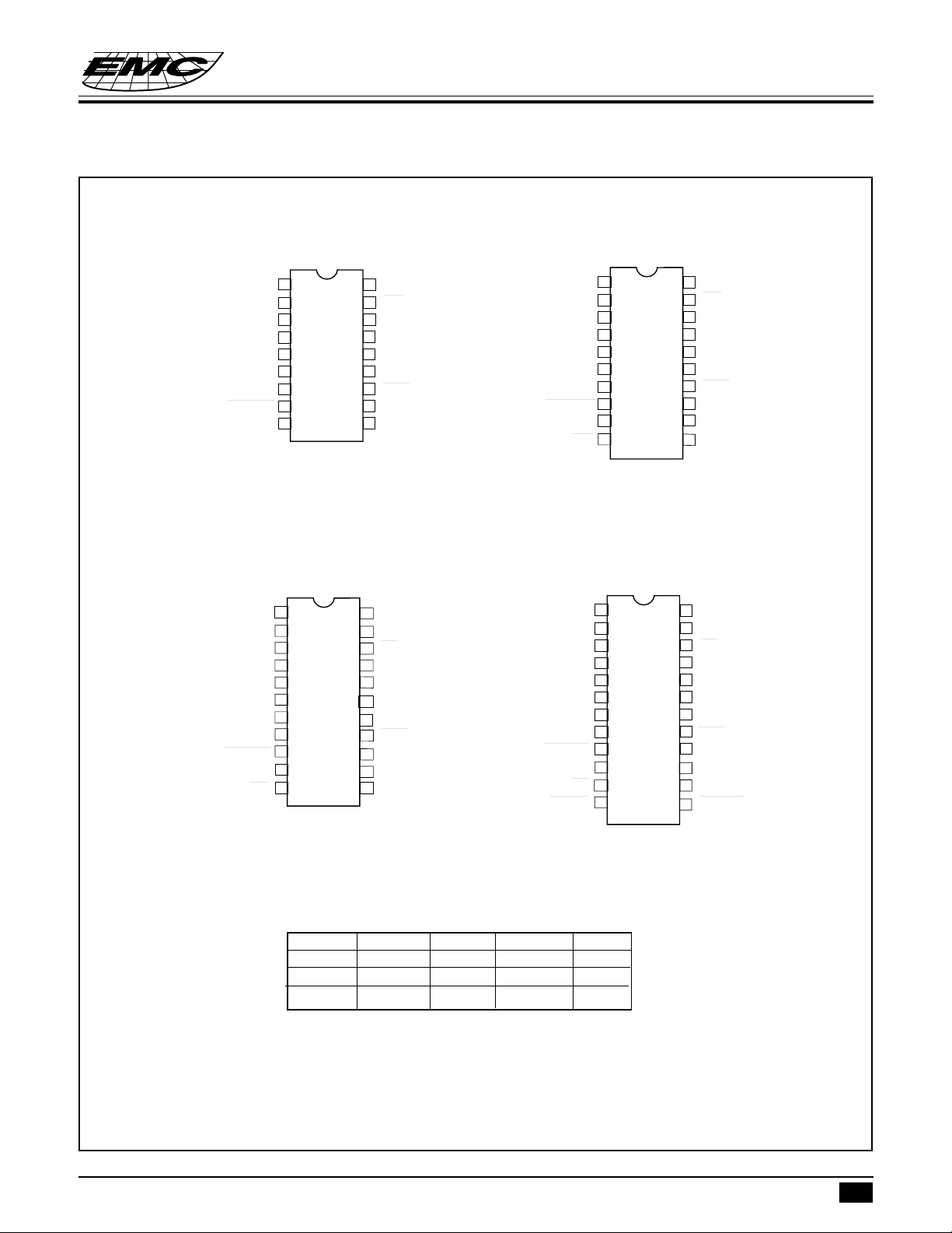
Pin Assignment
EM91455 SERIES
TONE/PULSE DIALER WITH LCD INTERFACE
AND I.P.P. DETECT FUNCTION
EM91455AP
COL5
COL4/KT
COL3
COL2
COL1
XIN
XOUT
XMUTE
VSS
EM91455CK
NC
COL5
COL4/KT
COL3
COL2
COL1
XIN
XOUT
XMUTE
VSS
HFI
10
11
EM91455BP
1
1
18
HDO
2
17
PO
3
16
ROW4
4
15
ROW3
5
14
ROW2
6
13
ROW1
7
12
HKS
8
11
VDD
9
10
DTMF
COL5
COL4/KT
COL3
COL2
COL1
XIN
XOUT
XMUTE
VSS
HFI
10
20
HDO
2
19
PO
3
18
ROW4
4
17
ROW3
5
16
ROW2
6
15
ROW1
7
14
HKS
8
13
VDD
9
12
DTMF
11
HFO
EM91455DK
NC
1
24
1
22
SDO
2
21
HDO
3
20
PO
4
19
ROW4
5
18
ROW3
6
17
ROW2
7
16
ROW1
8
15
HKS
9
14
VDD
13
DTMF
12
HFO
COL5
COL4/KT
COL3
COL2
COL1
XIN
XOUT
XMUTE
VSS
HFI
DRING
2
3
4
5
6
7
8
9
10
11
12
23
22
21
20
19
18
17
16
15
14
13
SDO
HDO
PO
ROW4
ROW3
ROW2
ROW1
HKS
VDD
DTMF
HFO
RMUTE
Keyboard Arrangement
ROW1
ROW2
ROW3
ROW4
COL1
1
4
7
*/T
COL2
2
5
8
0
* This specification are subject to be changed without notice.
COL3
3
6
9
#
COL4/KT
HD
F
RD/P
COL5
EM1
EM2
EM3
ST
9.24.1998
2
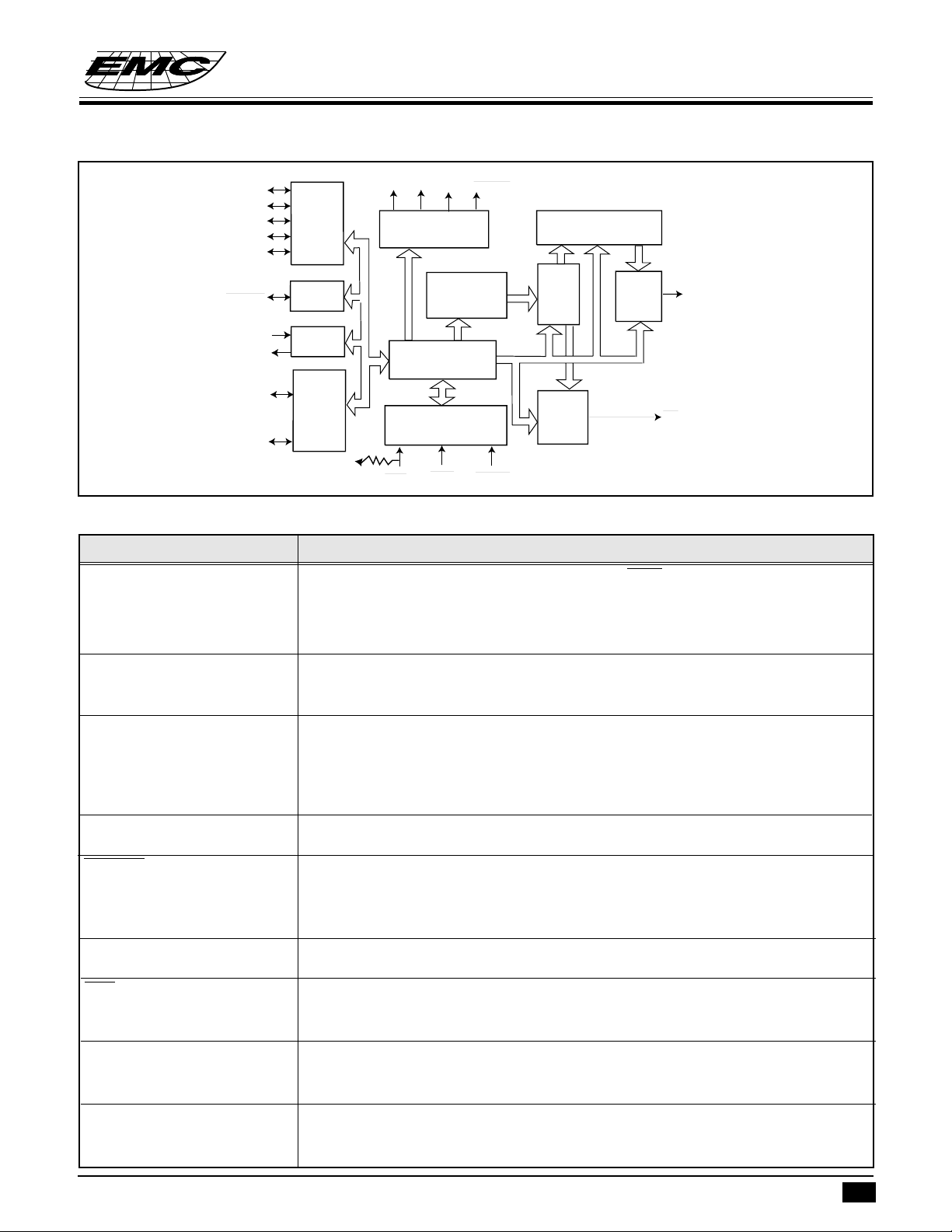
FUNCTIONAL BLOCK DIAGRAM
COL1
COL2
COL3
COL4/KT
COL5
Keyboard
interface
(column)
SDO
HFO
HDO
Output circuit
EM91455 SERIES
TONE/PULSE DIALER WITH LCD INTERFACE
AND I.P.P. DETECT FUNCTION
RMUTE
Row/Column
programming counter
XMUTE
XIN
XOUT
ROW1
ROW4
I/O circuit
Oscillator
Timing/Control circuit
Keyboard
~
interface
(Row)
VDD
HFI
Memory
Input circuit
HKS
DRING
latch
&
decoder
Pulse
generator
D/A
converter
DTMF
PO
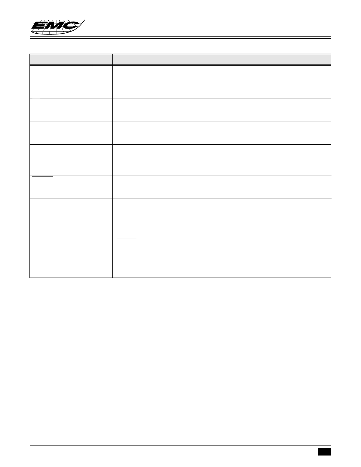
PIN DESCRIPTIONS
Symbol Function
ROW1~ROW4 Keyboard scan pins of row group. In idle state (HKS is “High” and HFO is “Low”),
these pins stay “High impedance” level to prevent power consumption. Otherwise,
these pins switch to “High” level for detecting keyboard entry. These pins will output
600 Hz signal while keyboard is scanning.
COL1~COL3 and COL5 Keyboard scan pins of column group. In idle state, these pins stay “High impedance”
level. Otherwise these pins switch to “Low” level for detecting keyboard entry. These
pins will output 600 Hz signal while keyboard is scanning.
COL4/KT The fourth column group pin of the keyboard that also provides the keytone output
. Normally, this pin stays “Low” level for detecting keyboard entry. After a valid
keyboard entry, this pin will output keying confirmation tone that is 600 Hz signal and
30 ms duration. To prevent signal interference, while DTMF issue, it will disable key
tone output except function key.
XIN and XOUT Oscillator input and output pins. A 3.579545 MHz crystal or ceramic resonator must
be crossed connection to XIN and XOUT pins which generate system clock.
XMUTE Input/Output structure pin. The output is a open drain structure. Input is schmitt trigger
structure. This pin will be input pin during ON-HOOK status for illegal parallel phone
detect input pin and will be output pin in OFF-HOOK condition for control speech
network.
VDD and V
SS
HFI Handfree inputs pin which accepts falling edge signal to turn “on” or turn “off”
HFO Handfree outputs pin that is designed to control telephone line for on-hook dialing or
DTMF The DTMF (Dual Tone Multi-Frequency) and music signals output pin. Normally,
Positive and negative power supply input pins. Recommended operating voltage from
2.0Vdc to 5.5Vdc.
handfree function. This pin is hysteresis input structure and built-in pull up resistor
(typically 200 Kohms).
control speakerphone circuit for handfree conversation. When handfree function is
executed, this pin will switch to“High”. Otherwise, this pin stays “Low” level.
this pin stays “Low” level. In Tone dialing mode, this pin will output DTMF signal
that is corresponding to keyboard 0 .. 9, * and # keys.
* This specification are subject to be changed without notice.
9.24.1998
3
EM91455 SERIES
TONE/PULSE DIALER WITH LCD INTERFACE
AND I.P.P. DETECT FUNCTION
Symbol Function
HKS Control signal inputs pin that is corresponding hook switch status. When handset was
left from cradle, this pin must be connected to “Low” level to operate all functions.
Otherwise, this pin must be connected to “High” level to disable all function and
prevent power consumption.
PO Pulse signal outputs pin that is NMOS open-drain output structure. Normally, this pin
stays “High impedance” level. In Pulse dialing mode and keypad was entry. This pin
will output pulse trains signal that is corresponding to keyboard 0 .. 9 keys.
HDO Hold function output that is CMOS structure.Normally, this pin stays “Low” level.
When Hold function is executing, this pin will output “High” level. This pin is
designed to drive LED or peripheral circuit to indicate line is at Hold status.
SDO SDO function output that is NMOS open-drain structure. When there is a valid entry
on keyboard, this pin will output a serial data. This serial data is designed to drive LCD
driver to display dialing number on LCD screen or drive voice synthesizer to announce
dialing number to speaker.
DRING The ring signal detect input pin.
While the Tel-ring is incoming, this pin must be connected to “Low” with delay to
indicate the ringing . Otherwise, this pin must be connected to “High” level .
RMUTE Ring mute output pin that is NMOS open-drain structure. The RMUTE pin is
designed to control microphone of handset to prevent the illegal dialing from pocket
dialer. If the DRING pin is at “High” level , then Off-Hook or turn on Handfree , this
pin will output “Low” level. In other words, the DRING pin is used to check the phone
that receives an incoming call (DRING =Low input) or make an outgoing call
(DRING= High input) . If the phone user make an outgoing call ,then RMUTE pin
activated to prevent the illegal dialing from pocket dialer in the particular application.
The RMUTE can be restored to “High” level when the first key entry is not the
optioned lock-number .
NC No connection.
* This specification are subject to be changed without notice.
9.24.1998
4
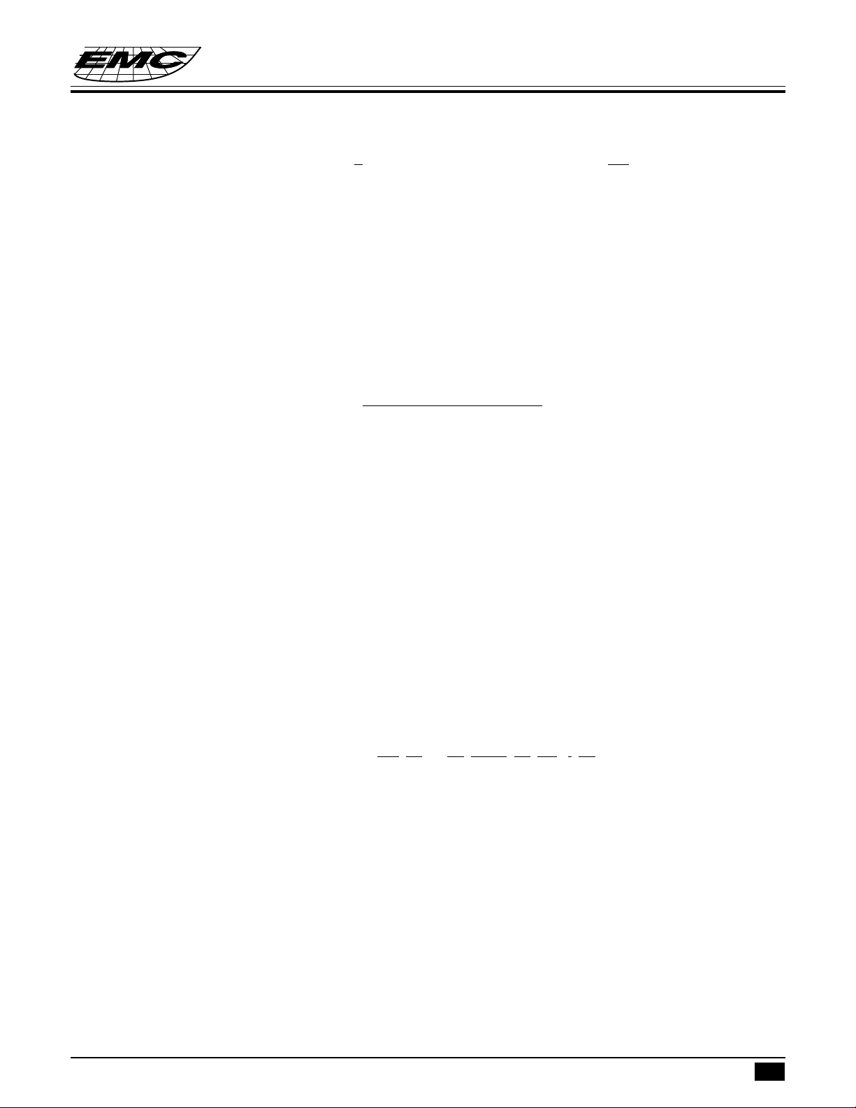
FUNCTION DESCRIPTIONS
Dialing signal selection
The EM91455 series incorporated a special keyboard scanning function that is connecting a resistor (typically
is 560 Kohms) on keyboard scan pin to select many telephone specifications. The specifications are described
as following :
a. Mode b. M/B ratio
ROW1 Mode ROW2 MBR (%)
R-Vdd 20 PPS NR 40:60
NR Tone R-Vss 33:66
R-Vss 10 PPS
c. Flash time d. Lock control method
ROW3 ROW4 Tf (ms) COL1 Control method
NR NR 600 R-Vdd key lock
NR R-Vss 100 NR none lock
R-Vss NR 80 R-Vss password lock
R-Vss R-Vss 300
EM91455 SERIES
TONE/PULSE DIALER WITH LCD INTERFACE
AND I.P.P. DETECT FUNCTION
e. Lock number
COL2 COL3 Lock number
NR NR none
NR R-Vss 0
R-Vss NR 9
R-Vss R-Vss 0,9
Normal dialing
Directly keying digital key on keyboard which number can be dialing output and stored in LNB memory
automatically. Operating procedure described as follow :
• To select Pulse or Tone mode.
• Off-hook or turn on HF function.
• Keying d1, d2, .. , dn. The “d” expressed digital keypad that included 1~9, *, 0, #, P, and P→T keys. The “n”
expressed unlimited.
• The numbers d1, d2, .. , dn will be dialed out in Pulse or Tone mode as selection.
LNB redial memory
Storing:
In normal dialing mode, every digital key was entry which number will be stored in LNB memory
automatically. If entry digits are more than 32 digits, the redial function of LNB memory will be disabled.
Otherwise, these numbers stored in LNB memory can be redial output.
* This specification are subject to be changed without notice.
9.24.1998
5
EM91455 SERIES
TONE/PULSE DIALER WITH LCD INTERFACE
AND I.P.P. DETECT FUNCTION
Redialing:
After normal dialing, directly keying F key (or On-Off hook once) and keying RD key on keyboard. The
numbers that are stored into LNB memory will be dialed output.
Repertory memory
The EM91455 series incorporated several sets repertory memory and each one can store number up to 16 digits.
These memories were designed to 3 sets types. In memory storing, if stored numbers are more than 16 digits
that only the previous 16 digits can be stored into specific memory. Otherwise, these numbers can be stored
entirely. After memory dialed out, the content of LNB is keeping to current data.
Storing of 3 sets memory
Direct (one-touch) operation
Off-hook (or turn on HF function), push (ST, d1, d2, .. , dn [ST], EMn The numbers d1, d2, .. , dn will be stored
into memory location “EMn”. The “EMn” expressed emergency memory EM1 to EM3.
Dialing (after memory dialed out, the content of LNB is keeping to current data)
Direct (one-touch) memory operation
• To select Pulse or Tone mode.
• Off-hook (or Turn on HF function), push “EMn” key. The numbers that are stored in direct memory location
“EMn” will be dialed out in Pulse or Tone mode as selection. The “n” expressed digital number from 1~3.
Pause (P) key operation
The Pause (P) key is designed to support pause operation in dialing duration. “P” key can be stored in memory
and it will occupy one digital position.
• To select Pulse or Tone mode.
• Off-hook (or turn on HF function), push (d1, d2, .. , dn, RD/P, k1, k2, .. , kn.) These numbers will be dialed
out as following sequence:
d1, d2, .. , dn, Tp, k1, k2, .. , kn.
Pulse to Tone (*/T) key operation
The Pulse to Tone (*/T) key is designed to support toll dialing (long distance call) or PABX system operation.
The “*/T” key can be stored in memory and it will occupy one digital position.
• To select Pulse mode.
• Off-hook (or turn on HF function), push d1, d2, .. , dn, */T, k1, k2, .. , kn. These numbers will be dialed out
as following sequence:
d1, d2, .. , dn, Tpt, k1, k2, .. , kn.
(pulse mode) (tone mode)
* This specification are subject to be changed without notice.
9.24.1998
6

EM91455 SERIES
TONE/PULSE DIALER WITH LCD INTERFACE
AND I.P.P. DETECT FUNCTION
Flash (F) key operation
The Flash (F) key is designed to break telephone line temporarily. After F key is depressed, this dialer will send
a flash signal to break line 600 ms, 300 ms, 100 ms or 80 ms as ROW3 and ROW4 selection.
Handfree (HF) function
The handfree function is designed to support on-hook dialing and loudspeaker application which can be turn “on”
or “off” with falling edge signal from HFI pin. During handfree function is executed, the HFO pin is switched
to “high”. Otherwise the HFO pin stays “low” level. One of the following operations can turn off Handfree
function (HFO pin return to “Low”).
• On-off hook once.
• Trigger HFI pin with falling edge signal.
• Turn on Hold (HD) function. (HDO pin switched to “High”)
Hold (HD) function
The Hold function is designed to stop conversation temporarily. In off-hook state (or HF function is turned on),
to press HD key on the keyboard, the Hold function can be turned “on” (HDO pin switched to “High”). One of
the following operations can turn off Hold function (HDO pin switched to “Low”).
• On-off hook once.
• To press HD key over 93 ms.
• Turn on Handfree (HF) function. (HFO pin switched to “High”)
Special Note:
A 300 ms delay time (Tdly) at the first Off-Hook or turn on Handfree that is a special designed to avoid a rapid
key entry (dummy number ) in this time duration ,and a long distance call number follows. For example,
Off-Hook , “3” ,............ , “0” ,1,2,3......
Dummy key Lock number key
The dummy number “3” is not detected by the centered office or PABX ,but the following numbers “0” ,1,2,
3... long distance call can be dialed out normally since the leading number “3” is not the Lock-number defined
in EM91455 series. To prevent the unavoidable long distance call, then EM91455 inhibits the key entry during
Tdly.
* This specification are subject to be changed without notice.
9.24.1998
7
EM91455 SERIES
TONE/PULSE DIALER WITH LCD INTERFACE
AND I.P.P. DETECT FUNCTION
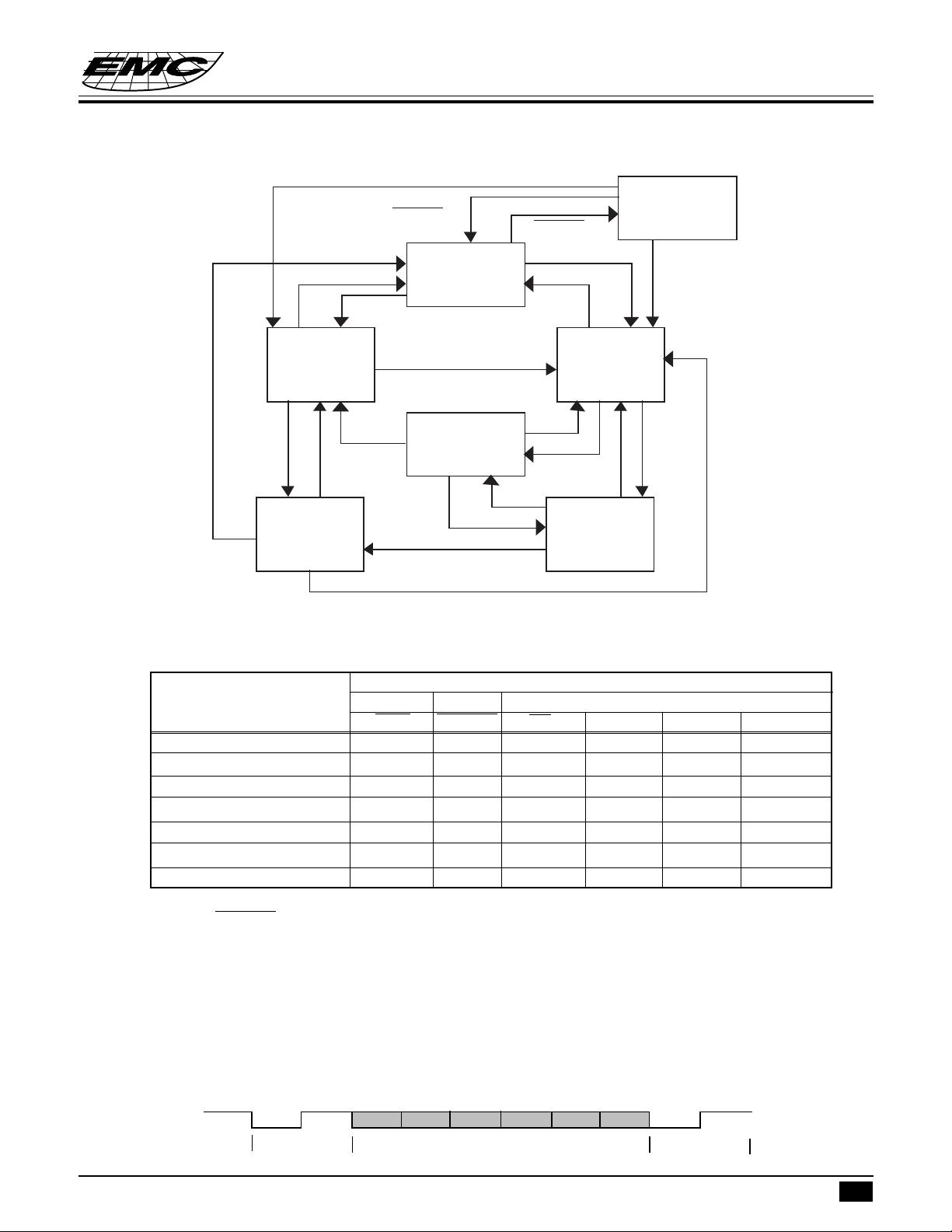
Operating flow chart
HD
HD
HF
(4)
On-hook
Hand-free State
HF
(6)
On-hook
Hold-line State
HF
HKS=Hi
HKS=Lo
XMUTE
On-hook State
Hand-free State
HKS=Hi
=Hi
(1)
HKS=Lo
(3)
Off-hook
HF
HD
XMUTE=Lo
HKS=Lo
HKS=Hi
HF
HF
HF
(7)
IPP State
HKS=Lo
(2)
Off-hook State
HD
HD
(5)
Off-hook
Hold-line State
<Note> : HF = Handfree
HD = Hold
Truth table
Pin level
Operating state Input I/O Output
HKS XMUTE PO HFO HDO DTMF
(1) On-hook, idle state H H/F F L L (2) Off-hook line L H/F F L L (3) Off-hook, HF line L H/F F H L (4) On-hook, HF line H H/F F H L (5) Off-hook, HD line L L/L F L H (6) On-hook, HD line H L/L F L H (7) IPP state H L/L F H H active
Note : F=floating (high impedance); H=logic “High”; L=logic “Low” level.
XMUTE are I/O port, so Input will effect state situation change, and which state dialer stay will
effect output level.
SDO (Serial Data Output) function
The SDO is serial data output which format is same as UART protocol. SDO function is designed to drive LCD
driver and voice synthesizer. So the dialing numbers can be display on LCD screen with EM32100 (or EM32117
). The SDO signal consists of two start bits, six data bits and two stop bits. The bit time is about 3.9 ms (256 Hz)
and output sequences are following by start bits, data bits (LSB to MSB) and stop bits.
ready
0
start bits
1 bit 0
bit1
* This specification are subject to be changed without notice.
bit2 bit3 bit4 bit5
data bits
0
stop bits
1
9.24.1998
8
 Loading...