

ELAN EM58P300 Datasheet

GENERAL DESCRIPTIONGENERAL DESCRIPTION
GENERAL DESCRIPTION
GENERAL DESCRIPTIONGENERAL DESCRIPTION
EM58P300 is a tiny-controller-based voice synthesizer/dual tone melody/dual tone sound effect IC which contains
all the function of EM58000 series and has an OTP (One Time Programmable) ROM inside.
FEATURESFEATURES
FEATURES
FEATURESFEATURES
• EM58P300 – ROM : 64k x 10 bits (21 sec@6K sample rate).
• Single power supply 2.4V ~ 5.5V.
• Port1 and Port2 with wake-up function, Port3.2 with programmable IR (38KHz carry) communication function.
• Power down mode for saving power consumption.
• Single ROM for voice, melody, sound effect and program data.
• Readable ROM code data.
• One 6-bit timer overflow control.
• Two stacks for subroutine calling.
• Dual channel output simultaneously : (voice + voice), (voice + dual tone melody) or (voice + dual tone sound
effect).
• 5-bit ASPCM synthesizer.
• Dual tone melody/sound effect generator with programmable envelope.
• Multiple playing sppeeds in 2KHz ~ 32KHz for voice playback.
• Multiple tempos and variable beats for dual tone melody/sound effect play-back.
• Multiple levels of volume control.
• Fixed current D/A to drive external connected transistor for audio output.
EASY SOUND -EASY SOUND -
EASY SOUND -
EASY SOUND -EASY SOUND -
TINY CONTROLLER-BASEDTINY CONTROLLER-BASED
TINY CONTROLLER-BASED
TINY CONTROLLER-BASEDTINY CONTROLLER-BASED
DUAL CHANNEL SOUND PROCESSORDUAL CHANNEL SOUND PROCESSOR
DUAL CHANNEL SOUND PROCESSOR
DUAL CHANNEL SOUND PROCESSORDUAL CHANNEL SOUND PROCESSOR
EM58P300 SERIESEM58P300 SERIES
EM58P300 SERIES
EM58P300 SERIESEM58P300 SERIES
PIN DESCRIPTIONSPIN DESCRIPTIONS
PIN DESCRIPTIONS
PIN DESCRIPTIONSPIN DESCRIPTIONS
Pin NO.Pin NO.
Pin NO.
Pin NO.Pin NO.
I/O I/O
I/O
I/O I/O
SymbolSymbol
Symbol
SymbolSymbol
FunctionFunction
Function
FunctionFunction
1 I P1.2/OEB/Mode option Bit 2 of Port 1 / Program control signal
2 I P1.1/PGMB/Mode option Bit 1 of Port 1 / Program control signal
3 I P1.0 Bit 0 of Port 1
4 I VSS Negative power supply.
5 I OSC/ACLK Oscillation component connection pin /
Program control signal
6 I TEST/Vpp Test/Programing.
7 O VO2 Voice output.
8 VO1 No connect
9 I VDD Positive power supply.
10 I/O P3.3 Bit 3 of Port 3.
11 I/O P3.2 Bit 2 of Port 3.
12 I/O P3.1 Bit 1 of Port 3.
13 I/O P3.0 Bit 0 of Port 3.
14 I/O P2.3 Bit 3 of Port 2.
15 I/O P2.2 Bit 2 of Port 2.
16 I/O P2.1/Dout Bit 1 of Port 2 / Program data output signal
17 I/O P2.0/Din Bit 0 of Port 2 / Program data input signal
18 I/O P1.3/Din.out.clk/Mode option Bit 3 of Port 1 / Program control signal
* This specification are subject to be changed without notice.
10.15.2001
1
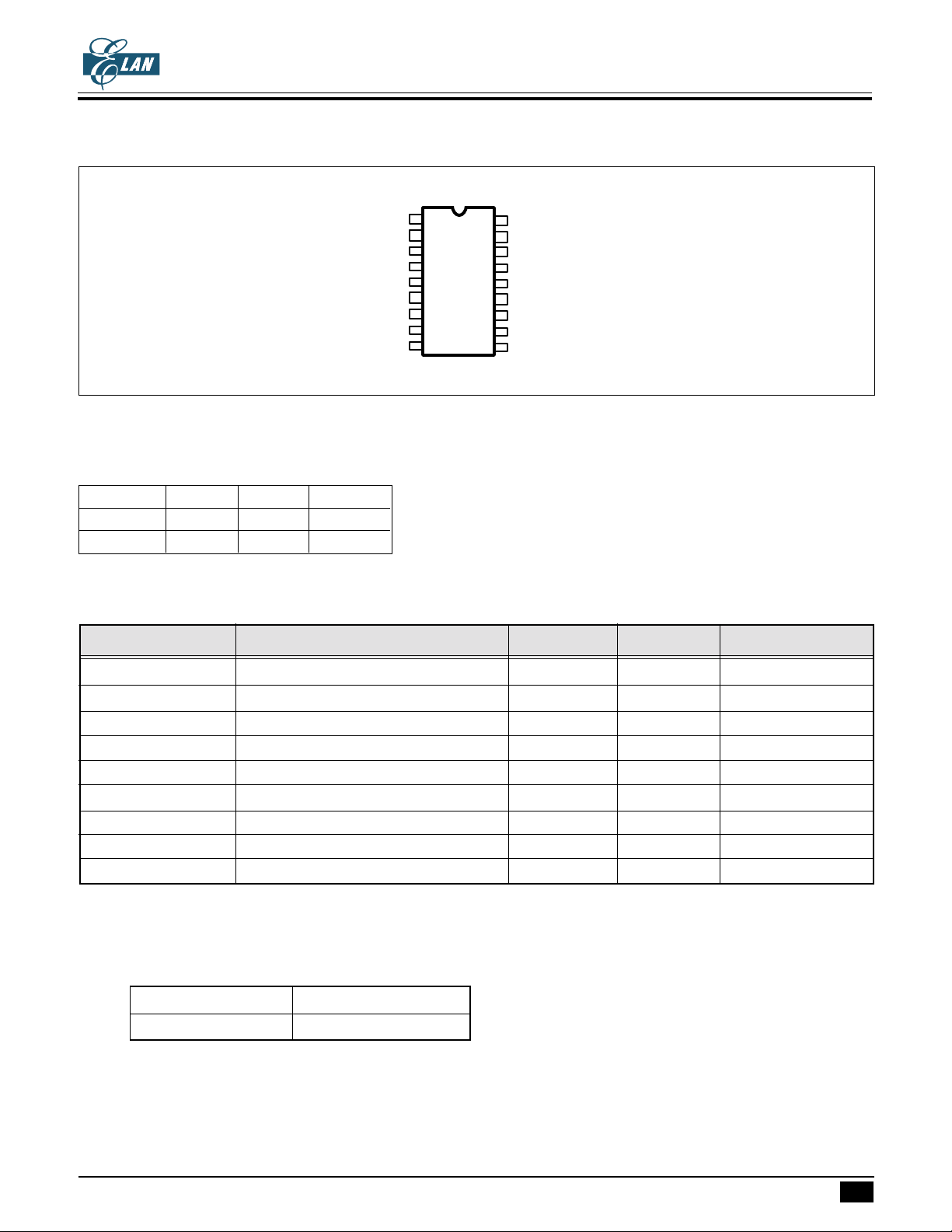
PIN ASSIGNMENTPIN ASSIGNMENT
PIN ASSIGNMENT
PIN ASSIGNMENTPIN ASSIGNMENT
EM58P300
EASY SOUND -EASY SOUND -
EASY SOUND -
EASY SOUND -EASY SOUND -
TINY CONTROLLER-BASEDTINY CONTROLLER-BASED
TINY CONTROLLER-BASED
TINY CONTROLLER-BASEDTINY CONTROLLER-BASED
DUAL CHANNEL SOUND PROCESSORDUAL CHANNEL SOUND PROCESSOR
DUAL CHANNEL SOUND PROCESSOR
DUAL CHANNEL SOUND PROCESSORDUAL CHANNEL SOUND PROCESSOR
EM58P300 SERIESEM58P300 SERIES
EM58P300 SERIES
EM58P300 SERIESEM58P300 SERIES
PROGRAMMING MODEPROGRAMMING MODE
PROGRAMMING MODE
PROGRAMMING MODEPROGRAMMING MODE
Mode P13 P12 P11
Regular 0 0 0
Security 0 0 1
TIMING PARAMETERTIMING PARAMETER
TIMING PARAMETER
TIMING PARAMETERTIMING PARAMETER
SymbolSymbol
Symbol
SymbolSymbol
P1.2
P1.1
P1.0
GND
OSC
VPP
VO2
VO1
VDD
ParameterParameter
Parameter
ParameterParameter
1
18
2
17
3
16
4
15
5
14
6
13
7
12
8
11
9
10
18 pin DIP
P1.3
P2.0
P2.1
P2.2
P2.3
P3.0
P3.1
P3.2
P3.3
Min.Min.
Min.
Min.Min.
Max.Max.
Max.
Max.Max.
UnitUnit
Unit
UnitUnit
Trs Level set up time 2 us
Tmcs Mode code setup time 2 us
Tdsu Data set up time 100 ns
Tdsh Data hold time 100 ns
Tas ACLK to byte select time 2 us
Tacpw Address clock pulse width 2 us
Tppw Program pulse width 100 us
Tps Programming mode set up time 4 us
Toed Output enable setup time 300 ns
Note : Segment ROM S1, S0 is programed just while 5 LSBs of ADDR are all 0.
Programming for security mode :
When programming in security mode, the waveform is just like above. The programming data is as below :
B11 ~ B1 B0
User defined Security bit
Note : When security = 0, enable security;
When security = 1, disable security.
* This specification are subject to be changed without notice.
10.15.2001
2
 Loading...