

Elan EL-TSTAT-8810 Safety & Installation Instructions
EL-TSTAT-8810
Safety & Installation Instructions

2
www.elanhomesystems.com
TABLE OF CONTENTS EL-TSTAT-8810
WI-FI SETUP
Wi-Fi Setup ________________________________________________________________________ 3
INSTALLATION
Installation Location Recommendations _____________________________________________________ 5
Outdoor Temperature Sensor (optional) _____________________________________________________ 6
Thermostat Mounting _________________________________________________________________ 7
Power & Reset Options ________________________________________________________________ 7
Wiring Terminal _____________________________________________________________________ 8
Wiring Diagrams ____________________________________________________________________ 9
SETUP & TESTING
System Setup Instructions _____________________________________________________________ 11
System Test Mode __________________________________________________________________ 18
REFERENCES
Quick Reference to Controls & Display ____________________________________________________ 22
Thermostat Features _________________________________________________________________ 23
Troubleshooting ____________________________________________________________________ 24
Specifications______________________________________________________________________ 26
Disclaimer ________________________________________________________________________ 26
TABLE OF CONTENTS
3
contact techsupport@elanhomesystems.com
WI-FI SET UP EL-TSTAT-8810
STEP 1
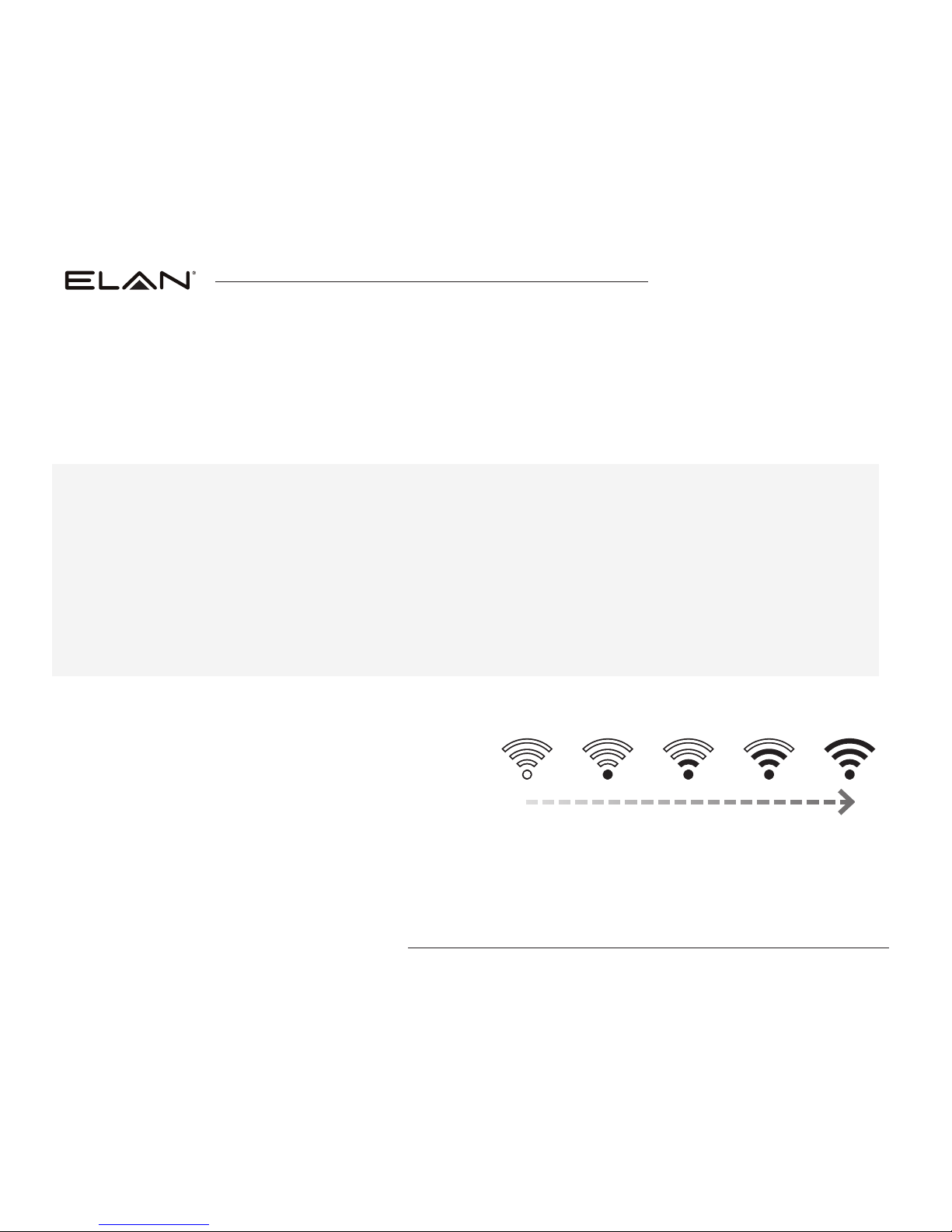
Verify the thermostat is in Wi-Fi Connection Mode.
The thermostat by default will be in Wi-Fi Connection
Mode. To confirm that the thermostat is in Wi-Fi
Connection Mode, verify that the radio bars on the
thermostat are strobing as shown below.
Note: If the thermostat is not in Wi-Fi Connection Mode,
refer to the Owner’s Manual for instructions on clearing
the Wi-Fi settings.
To connect the EL-TSTAT-8810 thermostat to a Wi-Fi network follow the steps below.
Note: You will need a computer or mobile device with Wi-Fi and a web browser.
WI-FI SET UP
IMPORTANT
Setting up your thermostat with an ELAN Controller
If you are installing an ELAN Thermostat with an ELAN Controller, please refer to the “ELAN Thermostat” Integration
Note for Wi-Fi setup and software configuration. ELAN Integration Notes are served through the ELAN tools and on
elanhomesystems.com/dealer-resources.
If you are planning to install the ELAN Thermostats when an ELAN controller is not present, please follow the
instructions below.

4
www.elanhomesystems.com
WI-FI SET UP EL-TSTAT-8810
STEP 2
Connect to the thermostat using a computer
or mobile device.
On your computer or mobile device, scan for
available networks. The thermostat should appear as
ELANSTAT8810XXXX followed by a unique identifier,
corresponding to the last 4 digits of the MAC address.
Connect to the thermostat you want to configure.
If you are installing multiple thermostats, you can
determine the MAC address of the specific thermostat
you are trying to configure by removing the cover on the
front of the thermostat to access the MAC address label.
If you are not, follow Wi-Fi setup below.
Open a web browser on your computer or mobile device.
In the browser enter:
http://192.168.1.99/elan.html
In the web browser interface select the network you
want to connect the thermostat to, and enter the
network’s security credentials.
STEP 3
Verify the thermostat is connected
to the Wi-Fi network.
Once all the required information is entered in the
web browser interface, the thermostat will connect to
the Wi-Fi network you selected. After the thermostat
is connected to the Wi-Fi network, the thermostat
will display the radio bars based on the Wi-Fi signal
strength. If the radio bars are not displaying the signal
strength, refer to Wi-Fi Maintenance and Troubleshooting
in the Owner’s Manual.
WI-FI SET UP (Continued)
5
contact techsupport@elanhomesystems.com
INSTALLATION EL-TSTAT-8810
Thermostat should be mounted:
• On an interior wall, in a frequently occupied space.
• Approximately 5‘ above floor.
• At least 18” from outside wall.
• Thermostat can be mounted to a vertical junction box.
• Within reliable range of the Wi-Fi network.
INSTALLATION LOCATION RECOMMENDATIONS
Do not mount thermostat:
• Behind doors, in corners, or other dead air spaces.
• In direct sunlight, near lighting fixtures, or other
appliances that give off heat.
• On an outside or unconditioned area wall.
• In the flow of a supply register, in stairwells,
or near outside doors.
• On a wall with concealed pipes or ductwork.
6
www.elanhomesystems.com
INSTALLATION EL-TSTAT-8810
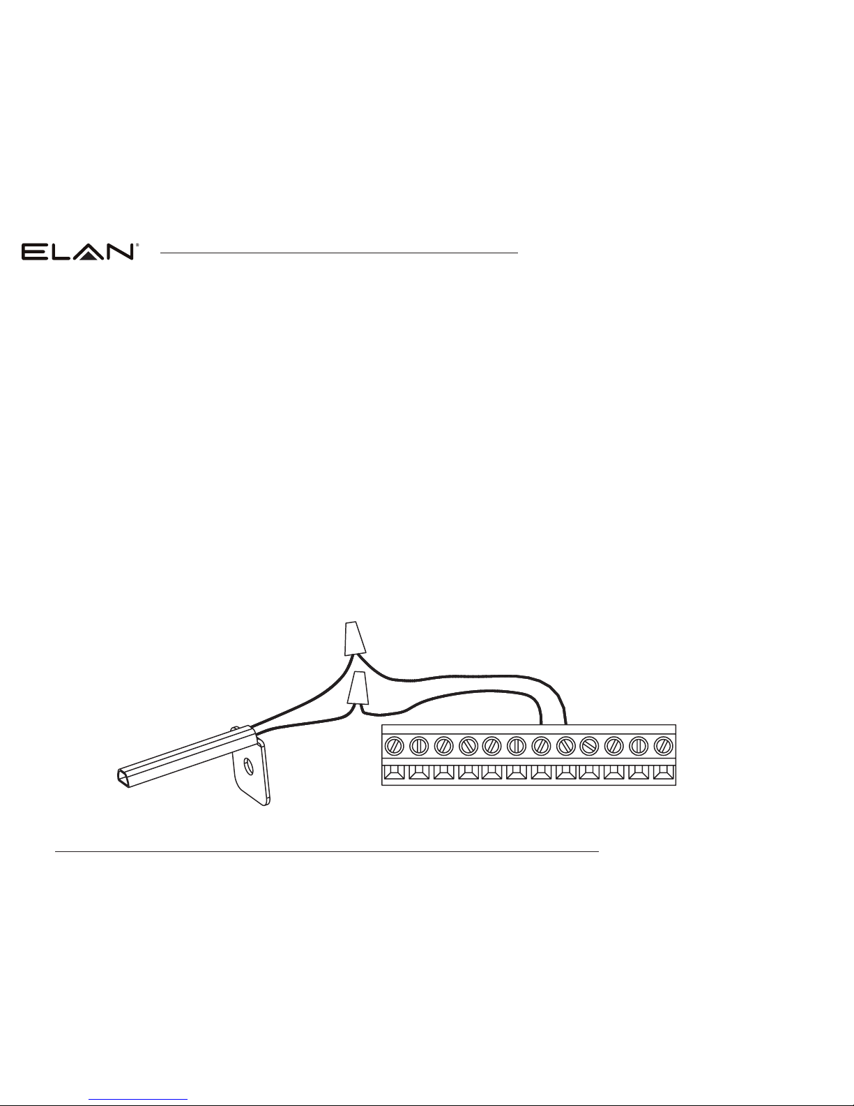
Outdoor temperature can be measured by attaching an EL-STAT-SEN-8052 sensor to the S1 and S2 terminals.
System setting #15 (Outdoor Sensor) is used to enable sensor.
Heat pump applications can use the outdoor temperature to effectively utilize the heat pump:
• When the outdoor temperature is less than the Low
Balance Point, the heat pump will be locked out and
only auxiliary heating will be used to provide heating.
• When the outdoor temperature is higher than the
High Balance Point, the auxiliary heating will be
locked out and only the heat pump will be used to
provide heating.
• Install on side of building out of direct sunlight
(north side recommended).
• Mount above snow line.
• Mount at least 3’ away from exhaust vents and
condensing lines.
• Maximum wire length is 300’.
• Do not route wires along 120 VAC lines.
C
G
Y
W
R
L
S1
S2
O/B
W2
Y2
RC
OUTDOOR TEMPERATURE SENSOR (Optional)
7
contact techsupport@elanhomesystems.com
INSTALLATION EL-TSTAT-8810
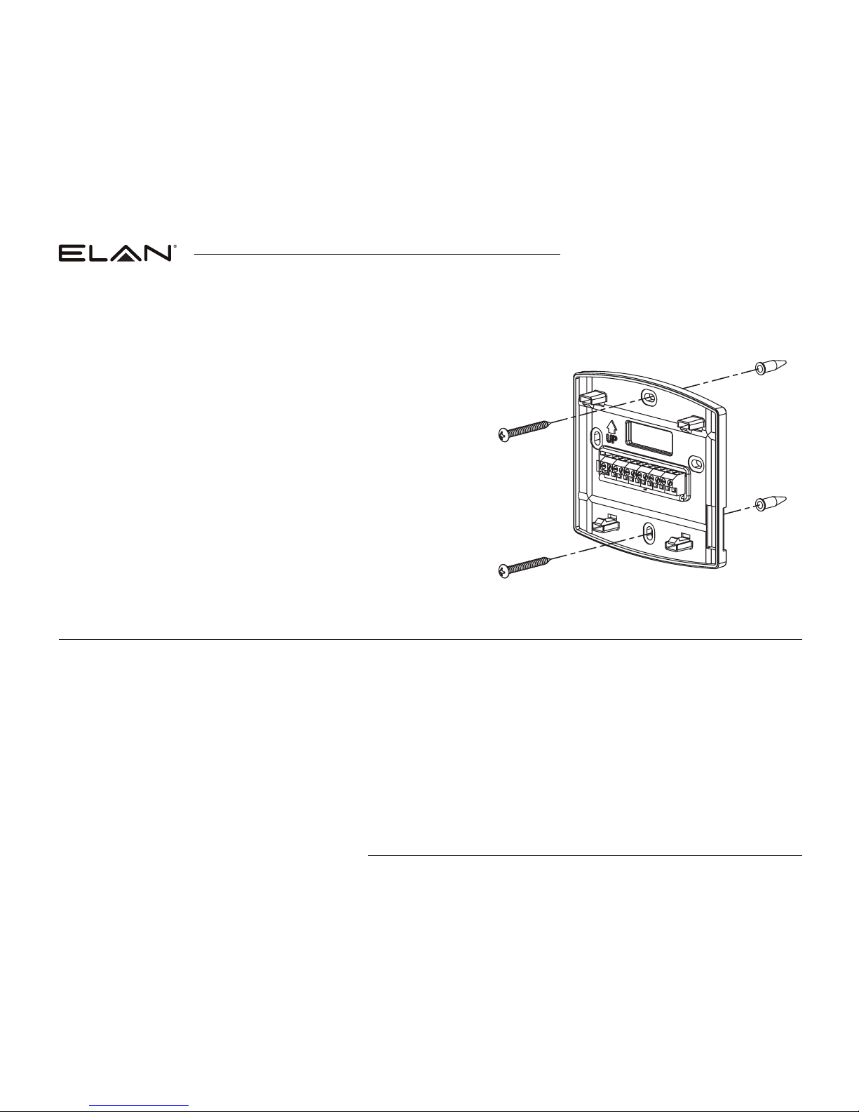
1. Remove the rear mounting plate from the thermostat.
2. Pull wires through the opening on the back of the rear
mounting plate.
3. Position and level the mounting plate of the thermostat on wall
and mark the hole locations with a pencil.
4. Drill 1/4” holes and insert supplied anchors (drywall only).
5. Place mounting plate over anchors, insert and tighten screws.
6. Seal wire entry holes to prevent drafts affecting temperature
readings.
The thermostat is powered from 24VAC. In the case of power loss the thermostat will maintain the clock for 24 hours.
The thermostat has a memory backup that saves the thermostat settings in case of power interruption.
The reset button located under the cover on the front of the thermostat can be used to reset the thermostat to factory
defaults. The system settings will also be set to default.
90-2033
THERMOSTAT MOUNTING
POWER & RESET OPTIONS
8
www.elanhomesystems.com
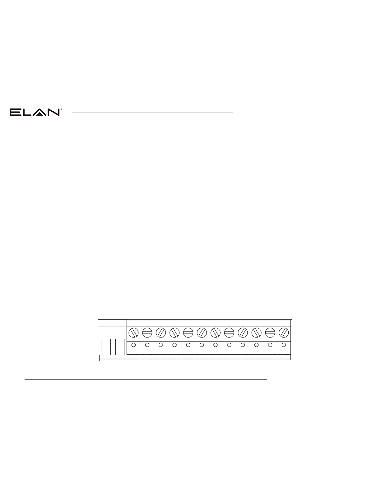
WIRE SPECIFICATIONS
18-24 gauge thermostat wire
INSTALLATION NOTES
• Ensure power at the HVAC
equipment is off.
• Loosen screw terminals,
insert stripped wire and
re-tighten.
• Push the excess wire back
into the opening and plug
the wall opening to prevent
drafts.
RC – 24 VAC supply cooling*
R – 24 VAC supply heating*
W – First stage heat (conventional) / First stage auxiliary (heat pump)
Y – First stage cooling (conventional) / First stage compressor (heat pump)
G – Fan
C – Common
S1 & S2 – Outdoor temperature sensor (optional)
O/B – Reversing valve
L – System fault indicator
W2 – Second stage heat (conventional) / Second stage auxiliary (heat pump)
Y2 – Second stage cooling (conventional) / Second stage compressor (heat pump)
* Jumper between RC & R is used in single transformer systems (see wiring diagrams).
C
G
Y
W
R
L
S1
S2
O/B
W2
Y2
RC
INSTALLATION EL-TSTAT-8810
WIRING TERMINAL
9
contact techsupport@elanhomesystems.com
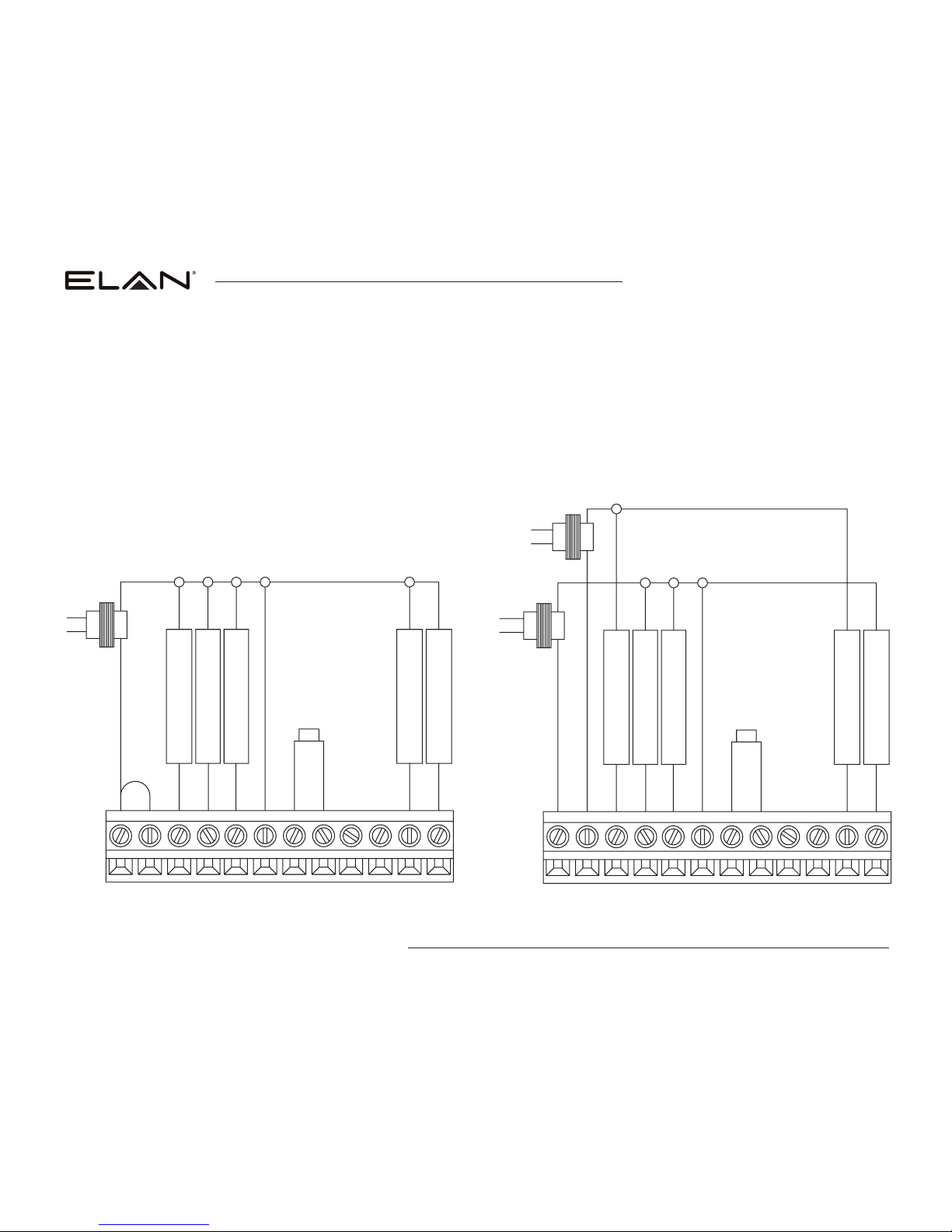
1st HEATING
1st COOLING
FAN
2nd HEATING
2nd COOLING
OUTDOOR TEMP
SENSOR
NOT USED
NOT USED
JUMPER
TRANSFORMER
C
G
Y
W
R
L
S1
S2
O/B
W2
Y2
RC
1st HEATING
1st COOLING
FAN
2nd HEATING
2nd COOLING
OUTDOOR TEMP
SENSOR
NOT USED
NOT USED
HEATING
TRANSFORME
R
COOLING
TRANSFORMER
C
G
Y
W
R
L
S1
S2
O/B
W2
Y2
RC
INSTALLATION EL-TSTAT-8810
WIRING
TWO TRANSFORMERS (REMOVE JUMPER WIRE)
FOR HEAT/COOL SYSTEM
SINGLE TRANSFORMER (USE JUMPER WIRE)
FOR HEAT/COOL SYSTEM
 Loading...