

Elan EL-IP-OTF2-WH Quick Start Manual

EL-IP-OTF2-WH
Quick Start Guide

2
www.elanhomesystems.com
QUICK START GUIDE
BEGINNING USING THIS CAMERA
IMPORTANT!!
If you are installing an ELAN Cameras and/or ELAN NVR with an
ELAN Controller, please refer to the “ELAN Surveillance” Integration
Note for setup and software configuration. ELAN Integration Notes
are served through the ELAN tools and on elanhomesystems.com/
dealer-resources. The software configuration information in this
document can be used to extend device control parameters for use
within an ELAN controller environment, or be used to operate this
hardware independent of an ELAN controller.
NOTES

3
contact techsupport@elanhomesystems.com
E L- I P- O T F 2- W H
NOTE
This equipment has been tested and found to comply with the limits
for a Class B digital device, pursuant to part 15 of the FCC Rules.
These limits are designed to provide reasonable protection against
harmful interference in a residential installation. This equipment
generates, uses and can radiate radio frequency energy and,
if not installed and used in accordance with the instructions, may
cause harmful interference to radio communications. However,
there is no guarantee that interference will not occur in a particular
installation. If this equipment does cause harmful interference to
radio or television reception, which can be determined by turning
the equipment off and on, the user is encouraged to try to correct
the interference by one or more of the following measures:
• Reorient or relocate the receiving antenna.
• Increase the separation between the equipment and receiver.
• Connect the equipment into an outlet on a circuit different
from that to which the receiver is connected.
• Consult the dealer or an experienced radio/TV technician for help.
Changes or modifications not expressly approved by the party
responsible for compliance could void the user’s authority to
operate the equipment.
4
www.elanhomesystems.com
QUICK START GUIDE
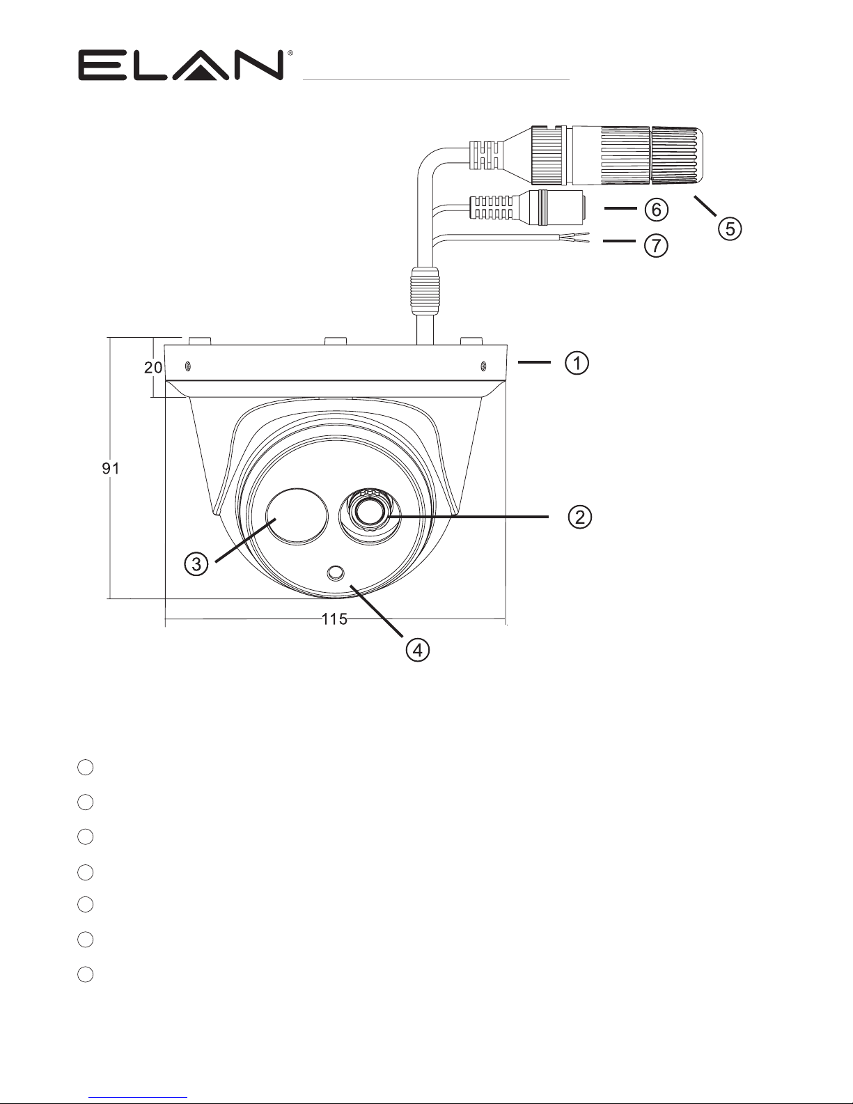
1
Upper cover
2
Lens
3
Infrared LED (IR LED)
4
Light sensor
5
RJ-45 Ethernet connector (supports PoE)
6
Power jack (DC12V ±10%)
7
Reset Wire (strip off the wire insulation if needed;
after the camera is reset, cut off the bare wire)
PART DESCRIPTION & DIMENSIONS
Unit: mm
 Loading...