

Page 1
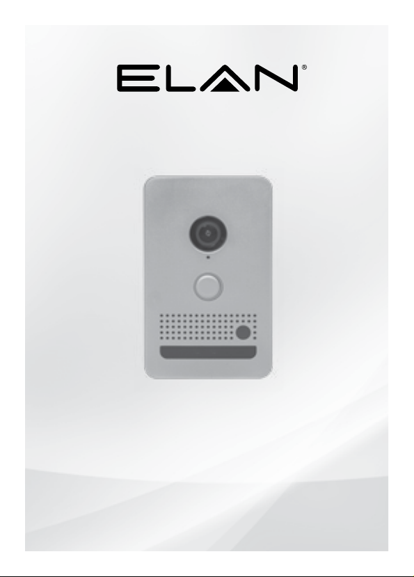
Intelligent Video Doorbell
EL-DB-BR | EL-DB-BK | EL-DB-NI
Quick Install Guide
Page 2

QUICK INSTALL GUIDE EL-DB
Thank you for including the EL AN Video Doorbell as part of the EL AN video
and inter face solution for your customer. It has been designed to provide
years of trouble free operation when wired and installed properly.
Included in the box
• 1ea Video Doorbell
• 1ea Pigtail Cable Connector
• 1ea Rough-in Mounting Bracket
• 1ea Mounting Hardware and Gaskets
• 1ea Security Screw Driver
• 3ea Extra Security Screws
SPECIFICATIONS
DIMENSIONS
Faceplate Size
3.5 x5.67 x .375 (in) / 89 x144 x 9.5 (mm)
Weight 0.55 lbs / .25 Kg
In-Wall Mounting Enclosure
2.87 x 4.7 x 1.97 (in) / 73 x 119.9 x 49.85 (mm)
Surface Mounting Enclosure
3.5 x 5.67 x 1.3 (in) / 89 x 144 x 33 (mm)
CONNECTIONS
Power: PoE - IEEE 803.2
48V / 13W (270mA) max.
Ethernet: 100 Mbps
Door Chime Relay: NO, rated 24VAC, 2A
Door Strike Relay: NO / NC dry contact,
rated 24VAC / 2A
Door Sensor: 5VDC–12VDC voltage
detection
Camera
Resolution: 720p
FPS: 30
Field of View: 140 degrees
Camera
Exposure: Automatic
Monitoring: Integrates with ELAN
Surveillance (NVR)
Microphone / Speaker
Audio: Full-Duplex
Processing: Echo / Noise cancellation
Volume, Equalization, Sensitivity:
Adjustable in software
Proximity Sensor
Type: Passive Infra-Red (PIR)
Detection: IntelliVision
reduces false positives
Range: Up to 5M, adjustable in software
Field of View: 120 degrees
General
Light Ring: Tunable color via software
Temperature Range:
-13F to 131F (-25C to 55C)
Humidity Tolerance: Up to 90%
Protection Rating: IP65
(continued)
®
Analytics
IMPORTANT SAFETY INSTRUCTIONS
1. Read these instructions.
2. Keep these instructions.
3. Hee d all warn ings.
4. Follow all instructions.
5. Do not u se this ap paratus near water.
6. Clean only with dry cloth.
7. Install in accordance with the manufacturer’s instructions.
8. Do not i nstall n ear any he at sourc es such as radiator s, heat registers,
stoves or other apparatus (including amplifiers) that produce heat.
9. Only use attachments/accessories specified by the manufacturer.
10. Unplug this ap paratus during l ightning storms or when unu sed for lo ng periods of time.
11. Refer all servicing to qualifie d serv ice personnel. Servicing is re quired w hen the
apparatus has be en dama ged in any way such as power-supply cord or plug is
damaged, liqui d has bee n spille d or objects have fal len into th e apparatus, the
apparatus has be en exposed to rain or moisture, does not o perate no rmally,
or has be en dropp ed.
12. If a Class I PoE a dapter or switch is us ed to provide power, be sure that the power
cord is firmly plugged into the socket and confirm the main earth connection.
CONSIGNES DE SÉCURITÉ IMPORTANTES
1. Lisez ces instructions.
2. Gardez ces instructi ons.
3. Respectez tou s les aver tisse ments.
4. Suivez toutes les instructions.
5. N’utilisez pas cet appare il près de l’eau.
6. Net toyez uniquement avec un chiffon se c.
7. Installez conformément aux instructions du fabricant.
8. Ne pas installer près de sources de chaleur telles que des radiateurs, bouches de chaleur,
cuisinières ou autres appareils (y comp ris les amplific ateurs) produisa nt de la chaleur.
9. Util isez uniquement les acc essoires/piè ces jointes spéc ifiés par le fabri cant.
10. Débranchez cet appare il en cas d’orage ou lors que vous ne l’utilisez pas pendant
longtemps.
11. Confiez toute réparation à un personnel qualifié. Une réparation est nécessaire si
l’appareil subit un dommage, par exemple si le cordon d’alimentation ou la fiche
est endommagé, s i un liquide a été renve rsé ou si des objets sont tombés dans
l’appareil, si l’appareil a été expos é à la pluie ou à l’humidi té, ne fonctionne pas
normalement, ou est tombé.
12. Si vous utilisez un adaptateur ou un commutateur PoE de classe I comme source
d’alimentation, assurez-vous que le cordon d’alimentation est branché fermement
dans la prise et as surez-vous qu’il s’agit d’une pri se de terre.
2 3
Page 3

QUICK INSTALL GUIDE EL-DB
FCC AND IC INFORMATION:
This Class B digital apparatus complies with Part 15 of the FCC rules
and with Canadian ICES-0 03
.
Operation is subject to the following two conditions:
1. This device may not cause inter ference and
2. This device must accept any interference, including interfe rence that may
cause undesired operation of the device.
Le présent appareil est conforme aux CNR d’Industrie Canada applicable s
aux appa reils radio exempts de lice nce. L’exploitation est autorisée aux deux
conditions suivantes: (1) l’appareil ne doit pas produire de brouillage, et (2)
l’utilisateur de l’appareil doit accepter tout brouillage radioélectrique subi,
même si le brouillage est susceptible d’en compromettre le fonctionnement.
CAN ICES-3B / NMB-3B
OVERVIEW
FRONT
Camera Lens
Microphone
Tuneable Illuminated LightRing
Doorbell Button
Speaker
PIR (motion detection)
IR Window
ATTENTION:
This ITE is to be connected only to PoE networks without routing to the outside plant or equivalent.
This product is intended to be supplied by a UL Listed Power Adapter or DC power source
marked “L.P.S.” (or “Limited Power Source”), rated 12 VDC, 2A max, Tma = 55 degree C or
48Vdc/13W (270mA) Gigabit Passive PoE injector, 802.3af/at PSE.
ATTENTION :
Cet ITE doit être connecté uniquement à des réseaux PoE sans acheminement vers une
installation externe ou équivalente. Ce produit doit être alimenté par un adaptateur secteur
homologué UL ou par une source d’alimentation CC marquée «LPS». (ou « source
d’alimentation limitée »), tension nominale de 12 VDC, 2A max, Tma = 55 °C ou 48Vdc/13W
(270 mA), injecteur PoE passif Gigabit, 802,3af/à PSE.
WARNING:
Changes or modi fications to this unit not expressly ap proved by th e part y responsible for
compliance could void the user’s authority to operate the equipment.
BACK
Mounting Holes
Network Data / Link Lights
Pigtail Terminal Connector
ATTENTION:
Les changements ou modifications apportés à cet appareil non expressément
approuvés par la partie responsable de la conformité peuvent annuler l’autorité
de l’utilisateur à utiliser l’équipement.
4 5
Page 4
QUICK INSTALL GUIDE EL-DB
PLANNING THE INSTALLATION
The ELAN Video Doorbell is primarily designed to be mounted in a portrait
orientation. It can be mounted in a landscape orientation, but the image will need
to be rotated using the ELAN configurator application (for more detail, please see
the Integration Note).
The video doorbell can be mounted flush using the included rough-in mounting
bracket, or surface mounted using the optional Surface Mount Box.
Power may be supplied by Power Over Ethernet (PoE) or by a 12V 2A DC power
supply (not included). PoE must meet the IEEE 802.3at standard. The video
doorbell connects to the local network via a hard wired Ethernet connection.
The video doorbell includes the following connections using the pigtail connector:
Description Designator
Network / PoE (RJ45)
DC input, positive (red) +
DC input, negative (black)
Door strike relay, normally closed contact NC
Door strike relay, common contact COM
Door strike relay, normally open contact NO
Door sensor input, positive DI+
Door sensor input, negative DIDoor Chime relay DB+
Door Chime relay DB
INSTALLING THE
VIDEO DOORBELL
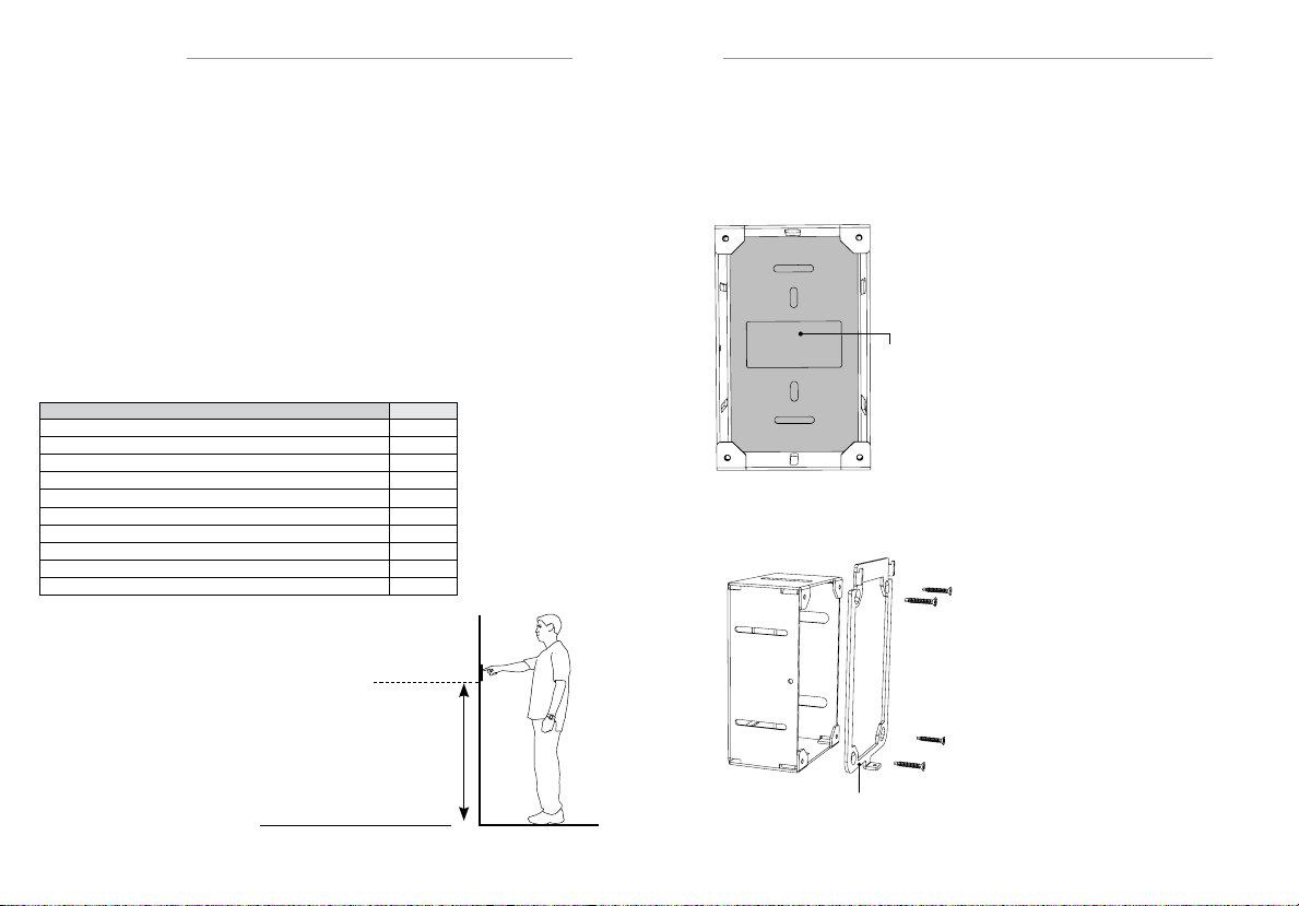
a. Mounting Height
The bottom of the video doorbell
should be mounted at a minimum
height of 50 in / 127cm from
the ground for optimized video
coverage.
50 in / 127 cm
-
-
b. Rough-in
The video doorbell mounts to the EL-DB-MB rough-in box using the included
mounting bracket. If surface mounting, use the optional surface mount kit without the rough-in box. See section f. Mounting - Surface
Place the vapor barrier in the rear of the
rough-in box and adhere the flaps to the
inside of the box. Once the vapor barrier is
in place, cut a slice to allow cable routing.
Place
the gasket
over rear of
rough-in box
and adhere to
the sides of
the box.
Mounting to an ELAN DBK-100
Rough-in Box
The video doorbell can be mounted to the
ELAN DBK-1000 rough-in mounting box.
If mounting to a DBK-1000, place the vapor
barrier in the rear of the DBK-1000 mounting
box and adhere the flaps to the inside of the
box. Once the vapor barrier is in place, cut a
slice to allow cable routing.
Attach the rough-in box to the structure.
The rough in box can be adjusted in / out
to accomodate different finish thicknesses.
Use the narrow slots to attach the screws,
the wider slots are used for tool access.
Attach the adhesive gasket to the mounting
bracket (note the alignment of the holes on
the bracket and the gasket making sure they
line up before adhering it). Next, attach the
mounting bracket to the rough-in box using
the included #6 Phillips head screws.
ROUGH-IN BOX
MOUNTING
BRACKET
6 7
Page 5
QUICK INSTALL GUIDE EL-DB
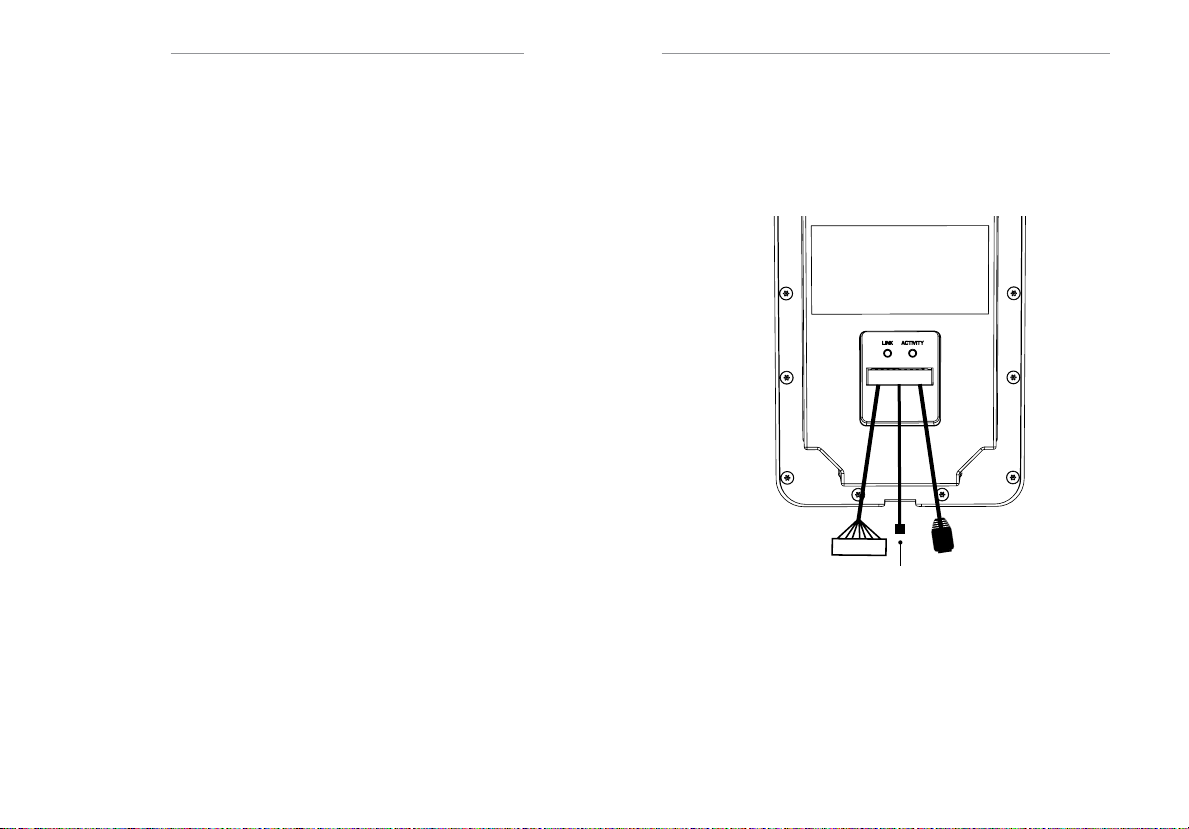
c. Make the Connections
Connect using the included pigtail connector. Route the connections through
the large opening on the back of the rough-in box.
Connecting to the network / PoE
Connect to the LAN using the RJ45 connector. If connecting using a
PoE switch an additional power source is not necessary. Optionally, the video
doorbell can be powered using a 12V 2A power supply (not included).
Connecting Power
While using PoE is recommended, the DC input can be used optionally where
PoE is not available. Using a 12V 2A power supply, connect to the DC input
connector. Red wire is positive, black wire is negative. Do not connect PoE
and DC power simultaneously.
Connecting the Relay
The video doorbell includes a relay to open a gate or electronic door strike that
can be triggered via the ELAN system. The relay provides normally open and
normally closed contacts to support fail safe or fail secure operation. Refer to
your gate opener instructions for configuration information.
Connecting the Door Sensor Input
The video doorbell interfaces to a door sensor such as a magnetic contact
switch. Connect the wires of the door sensor to the DI+ and DI- inputs on the
terminal connector. The door sensor will need to be set up as normally-open or
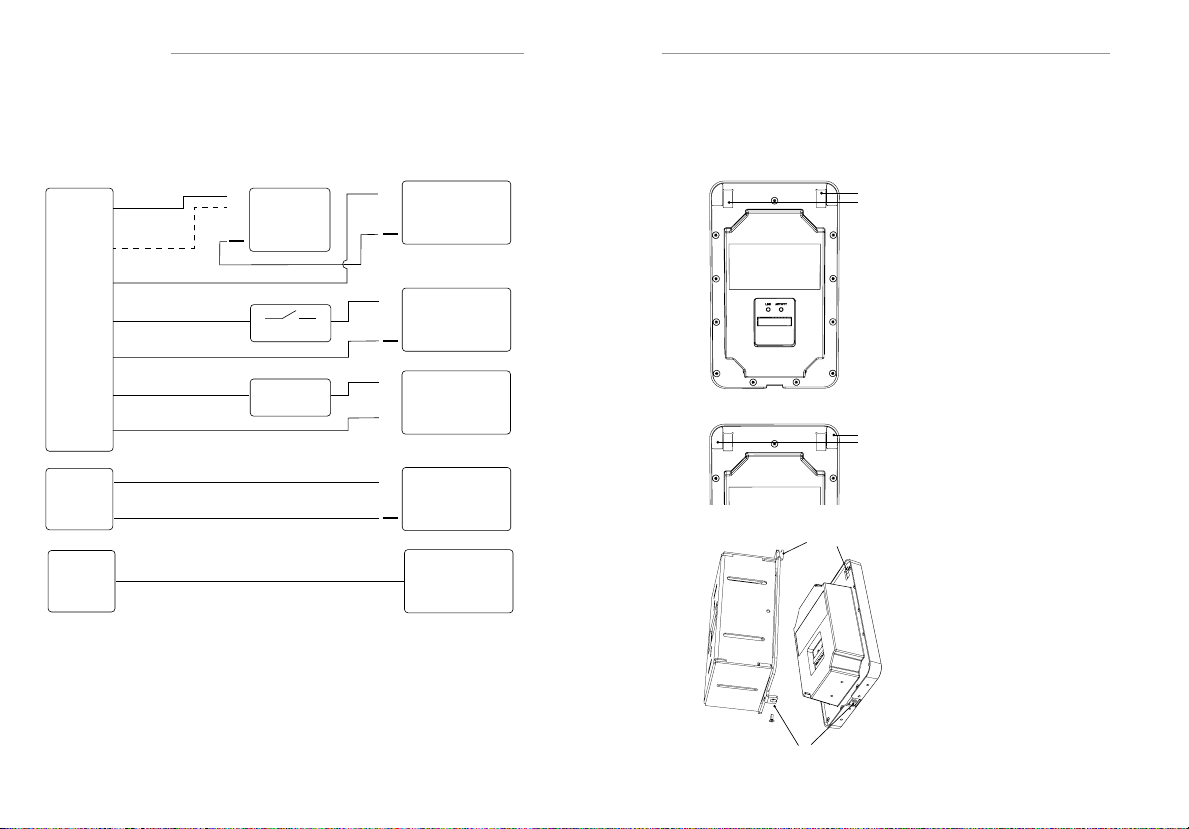
normally-closed. An external 12VDC power supply must be connected through
the door sensor to the video doorbell. Refer to the wiring diagram on page 10.
Connecting the Door Chime Relay
The video doorbell can ring a standard door chime. Connect the positive and
negative terminals to the DB+ and DB- inputs on the terminal connector.
RJ45
NC
NO
COM
DI+
DI-
DB+
DB-
Network / PoE
DC Input
Note: the RJ45 connector block should be on the right side of the
terminal connector, as shown here.
8 9
Page 6
QUICK INSTALL GUIDE EL-DB
Wiring
d. Wiring
NO
NC
COM
DI+
DI-
DB+
DB-
12V
GND
RJ45
Fail-Secure
Fail-Safe
+
Access
Sensor
Chime
+
+
~
~
+
24V DC
12V DC
24VAC
XFMR
12V DC
PoE / LAN
e. Mounting – Rough-in
Once the the rough-in bracket has been installed and connections are made,
the video doorbell can me mounted.
Mounting hook holes
Connect the pigtail connector
to the network, power, relay,
door sensor, or door chime as
necesary, described in section
c. Route the end of the pigtail
connector through the large hole
in the rough-in box from the rear.
Connect the pigtail terminal
to the video doorbell.
Top Corners
Mounting hooks
Add the smalll adhesive pieces
to top corners on the back of the
video doorbell.
Place the video doorbell on the
mounting hooks and slide the
video doorbell down.
Using the included screw driver
and M2 screw, attach the video
doorbell to the bottom tab of the
mounting bracket.
Security Screw
10 11
Page 7
QUICK INSTALL GUIDE EL-DB
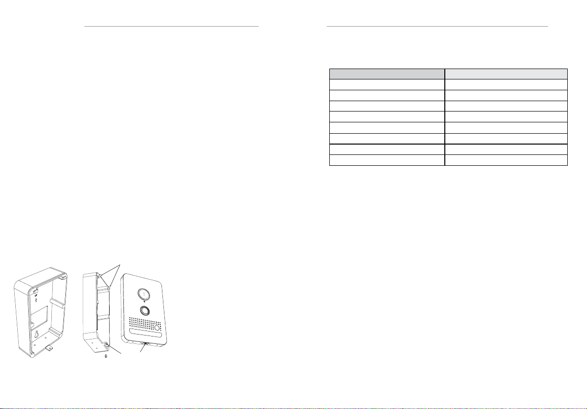
f. Mounting - Surface
The video doorbell can be surface mounted using the optional surface mount
box (sold separately in each color).
Connect the pigtail connector to the network, power, relay, door sensor, or door
chime as necesary, described in section b.
Route the end of the pigtail connector through the large hole in the surface
mount box from the rear.
Attach the adhesive gasket from the Video Doorbell kit to the rear of the surface
mount box and attach the surface mount box to the wall.
Connect the pigtail terminal to the video doorbell.
The surface mount box does not accommodate the pigtail connector which
should be placed in the wall behind the doorbell using a 1.5” opening in the wall.
If a 1.5” inch opening behind the surface mount box cannot be made and is too
small to fit the connectors, the two terminal block connectors can be removed.
If necessary, those connections can be wired directly.
If the opening is still too small to fit the RJ45 connector, that connector can also
be trimmed off and the connections can be wired directly (see Ethernet wiring on
the following page).
Mounting hooks
M2 Screw
Place the video doorbell
on the mounting hooks
and slide the video
doorbell down.
Using the included screw
driver and M2 screw,
attach the video doorbell
to the bottom tab of the
mounting bracket.
g. Ethernet Wiring
ELAN Video Doorbell Standard (TIA568B)
White + Orange White + Orange
Orange Orange
White + Green White + Green
White + Red Blue
Red White + Blue
Green Green
White + Black White + Brown
Black Brown
TROUBLESHOOTING
a. Factory Reset
Reset a unit to DHCP:
1. Disconnect power from the unit
2. Press and hold the doorbell button and connect power
3. Continue to hold the doorbell button for 20 seconds until the LightRing
flashes red
4. Connect directly to the video doorbell using a static IP address on a PC
a. Set the PC to a static IP address of 192.168.100.99.
b. Connect the video doorbell directly to the PC using an Ethernet cable
(if connecting through a switch, disconnect any other devices)
c. Using a web browser navigate to 192.168.100.100
d. Navigate to the System tab and click restore defaults to reset to DHCP
or navigate to the Network tab and select the dropdown for DHCP
12 13
Page 8

QUICK INSTALL GUIDE EL-DB
b. Factory Reset - Continued
Reset an unresponsive unit:
Try resetting the unit to DHCP first before following the instructions below
1. Disconnect power from the unit
2. Press and hold the doorbell button and connect power
3. Continue to hold the doorbell button for 20 seconds until the LightRing
flashes red
4. Connect directly to the video doorbell using a static IP address on a PC
a. Set the PC to a static IP address of 192.168.100.99.
b. Connect the video doorbell directly to the PC using an Ethernet cable
(if connecting through a switch, disconnect any other devices)
5. Using a web browser navigate to 192.168.100.100
From here, the unit can be reset to DHCP, given a static IP address, or have
firmware updated.
To update rmware:
1. Locate the latest firmware file available on the ELAN Dealer Resources
page and download it
2. Navigate to the Software tab
a. Browse for the file downloaded in step 1
b. Click Update
3. The unit will update and reboot.
c. LightRing Status Indicator
- Flashing Blue - Connecting to the network
- Flashing Red - No SIP connection to the System Controller
NOTES
14 15
Page 9

LIMITED WARRANTY
Nortek Securit y & Control ( ‘NSC’ ) warrants the EL AN Video Doorbell to be free from defects
in materials and workmanship for the period of two years (2 years) from the date of purchase.
If within the applicable warrant y period above purchaser discovers that such item was not as
warranted above and promptly noti es ‘NS C’ in writing, ‘NSC’ shall repair or replace the item
at the company’s option. This warrant y shall not apply (a) to equipment not manufactured by
‘NSC’, (b) to equipment which shall have been installed by other than an ‘NSC’ authorized
installer, (c) to installed equipment which is not installed to ‘NSC’s’ specications, (d) to
equipment which shall have been repaired or altered by others than ‘N SC’, (e) to equipment
which shall have been subjected to negligence, accident, or damage by circumstances beyond
‘NSC’s’ control, including, but not limited to, lightning, ood, electrical surge, tornado,
earthquake, or other catastrophic events beyond ‘NSC’s’ control, or to improper operation,
maintenance or storage, or to other than normal use of service. W ith respect to equipment
sold by, but not manufactured by ‘NSC’, the warranty obligations of ‘NSC’ shall in all respects
conform to the warranty actually extended to ‘NSC’ by its supplier. The foregoing warranties
do not cover reimbursement for labor, transportation, removal, installation or other expenses
which may be incurred in connection with repair or replacement. E xcept as may be expressly
provided and authorized in writing by ‘NSC’, ‘NS C’ shall not be subject to any other obligations
or liabilities whatsoever with respect to equipment manufactured by ‘N SC’ or ser vices
rendered by ‘NSC’.
THE FOREGOING WA RRANTIES A RE EXCLU SIVE AND IN LIE U OF ALL OTH ER EXPRESSED AND
IMPL IED WA RRANT IES E XCEP T WARR AN TIES OF TIT LE, INCLU DING BUT NOT LIMITED TO
IMPL IED WA RRANT IES OF M ERCHAN TABIL IT Y AND F ITN ESS FOR A PART ICU LA R PUR POSE.
ATTENTION: TO OUR VALUED CUSTOMERS
To ensure that customers obtain quality pre-sale and after-sale support and service,
Nortek Security & Control products are sold exclusively through authorized dealers.
Nortek Security & Control products are not sold online.
The warranties on Nortek Security & Control products are NOT VALID if the products
have been purchased from an unauthorized dealer or an online E-tailer. To determine
if your Nortek Security & Control reseller is authorized, please call Nortek Securit y
& Control at (707) 283-5900.
www.nortekcontrol.com
©2019 Nortek Security & Control, LLC. All rights reserved. ELAN
®
IntelliVision
are registered trademarks of Nortek Security & Control, LLC.
®
and
P/N: 10023145 Rev J
 Loading...