

Page 1
E L- 4 K M - V W 4 4
User Manual
VideoMatrix
1 2 3 4
IR
Power
Lock
Matrix Video-Wall Multi-View
HDMI
VGA
Input
Output
All
Menu Up Esc
Select Down Enter
EL-4KM-VW44
1
2 3 4
1
2 3 4
IR Input IR Output
RS-232
TCP/IP
1 2 3 4 1 2 3 4
HDMI Output HDMI Input
VGA 1
VGA 2
VGA 3
VGA 4
L/R 1
L/R 2
L/R 3
L/R 4
IR Ext.
Off
On
VGA Input
12V
3A
VideoMatrix
1 2 3 4
IR
Power
Lock
Matrix Video-Wall Multi-View
HDMI
VGA
Input
Output
All
Menu Up Esc
Select Down Enter
Page 2
EL-4KM-VW44 USER MANUAL
02
www.elanhomesystems.com
Introduction 03
Features 03
Panel Descriptions 04
Control Ports 05
Matrix Front Panel Control - Turning On/Off Outputs 06
Matrix Front Panel Control - EDID Management 06
Matrix Front Panel Control - Video Input Selection 07
Matrix Front Panel Control - Matrix Mode 07
Matrix Front Panel Control - Video Wall Mode 08-09
Matrix Front Panel Control - Multi-View Mode 10 -11
Infrared Distribution 12
Infrared Remote Control 13
EDID Control 14
Application Diagram 15
Specifications 16
Package Contents 16
Maintenance 16
RS-232 and Telnet Commands 17-18
Infrared Commands 19-20
Web Browser Interface 21
Certifications 22
Contents
Surge protection device
recommended
This product contains sensitive electrical components that may be damaged by electrical spikes,
surges, electric shock, lightning strikes, etc. Use
of surge protection systems is highly recommended in order to protect and extend the life of
your equipment.
Safety And
Performance Notice
The transmission distances of HDMI over UTP
cables are measured using TE CONNECTIVITY
1427071-6
EIA/TIA-568-B termination (T568B) of cables is
recommended for optimal performance.
To minimize interference of the unshielded
twisted pairs in the CAT5e/6 cable do not run
the HDBaseT/Cat5e /6/6a cabling with or in close
parallel proximity to mains power cables.
Do not substitute or use any other power supply
other than the enclosed unit, or a ELAN approved
replacement.
Do not disassemble either the Transmitter or
Receiver units for any reason. Doing so will void
the manufacturer’s warranty.
Thank you for purchasing
this product.
For optimum performance and safety, please
read these instructions carefully before connecting, operating or adjusting this product.
Please keep this manual for future reference.
Page 3

03
contact techsupport@ elanhomesystems.com
EL-4KM-VW44 USER MANUAL
The ELAN 4 x 4 HDMI/VGA matrix with Video Wall and Multi-viewer options is a multipurpose high-speed video processing system. The EL-4KM-VW44 can be configured
for 3 different output modes. The EL-4KM-VW44 can perform as a 4x4 seamless
matrix switcher, as a 2x2, 4x1 or 1x4 video wall solution and as a quad multi-view
presentation system.
Inputs can be assigned as either HDMI or VGA with associated L/R analog audio with
control of the switcher via the front-panel push buttons, IR remote control, RS-232
interface, TCP/IP and Web GUI interface.
Introduction
• Features 3 operational modes:
- 4x4 Matrix (selected HDMI or VGA inputs)
- Video wall (2x2, 4x1 or 1x4 configuration)
- Multi-viewer mode
• Features 4x video inputs that can be configured as HDMI video or VGA video with associated L/R analog audio
• Seamless video switching
• Video inputs support all industry standard video resolutions including VGA-WUXGA (up to 1920x1200 @60Hz)
and 480i-4K (3840 x 2160 @30Hz 4:4:4, 4096 x 2160 @24Hz 4:4:4)
• HDMI output resolution fixed to 1080p 60Hz
• Maximum PCM 7.1 96 KHz audio input, PCM 2CH 96KHz audio output.
• IR routing
• Supplied with 4x 5v-to-12v IR converter cables (EL-4KACC-IR-CAB)
• Control via front panel, IR, RS-232 and TCP/IP
• Web Interface Module for control and configuration of the Matrix
• Advanced EDID management
Features:
Page 4
EL-4KM-VW44 USER MANUAL
04
www.elanhomesystems.com
EL-4KM-VW44
1
2 3 4
1
2 3 4
IR Input IR Output
RS-232
TCP/IP
1 2 3 4 1 2 3 4
HDMI Output HDMI Input
VGA 1
VGA 2
VGA 3
VGA 4
L/R 1
L/R 2
L/R 3
L/R 4
IR Ext.
Off
On
VGA Input
12V
3A
VideoMatrix
1 2 3 4
IR
Power
Lock
Matrix Video-Wall Multi-View
HDMI
VGA
Input
Output
All
Menu Up Esc
Select Down Enter
VideoMatrix
1 2 3 4
IR
Power
Lock
Matrix Video-Wall Multi-View
HDMI
VGA
Input
Output
All
Menu Up Esc
Select Down Enter
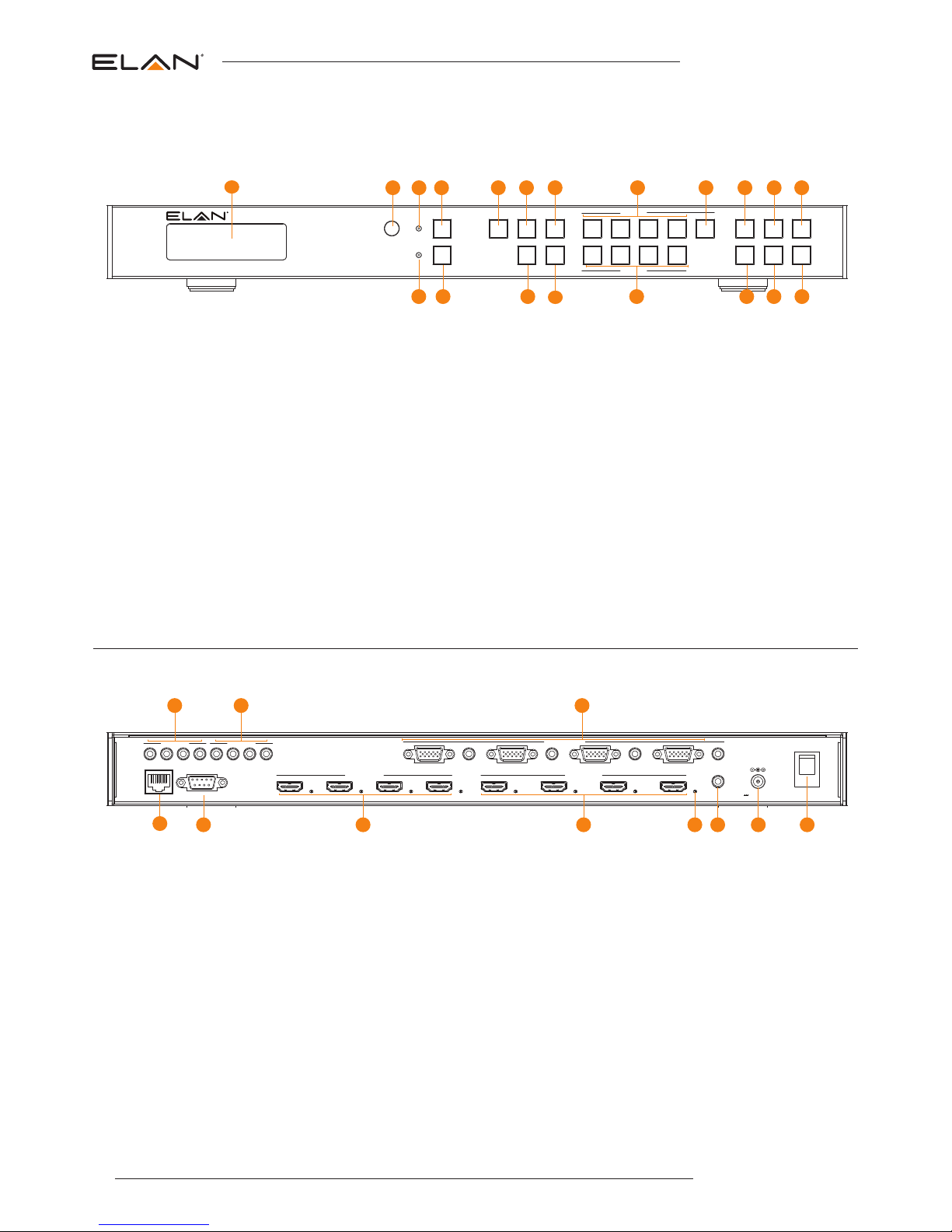
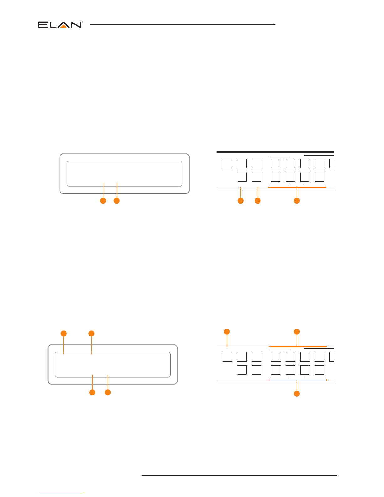
Rear Panel
1 2 3
108 9765
4
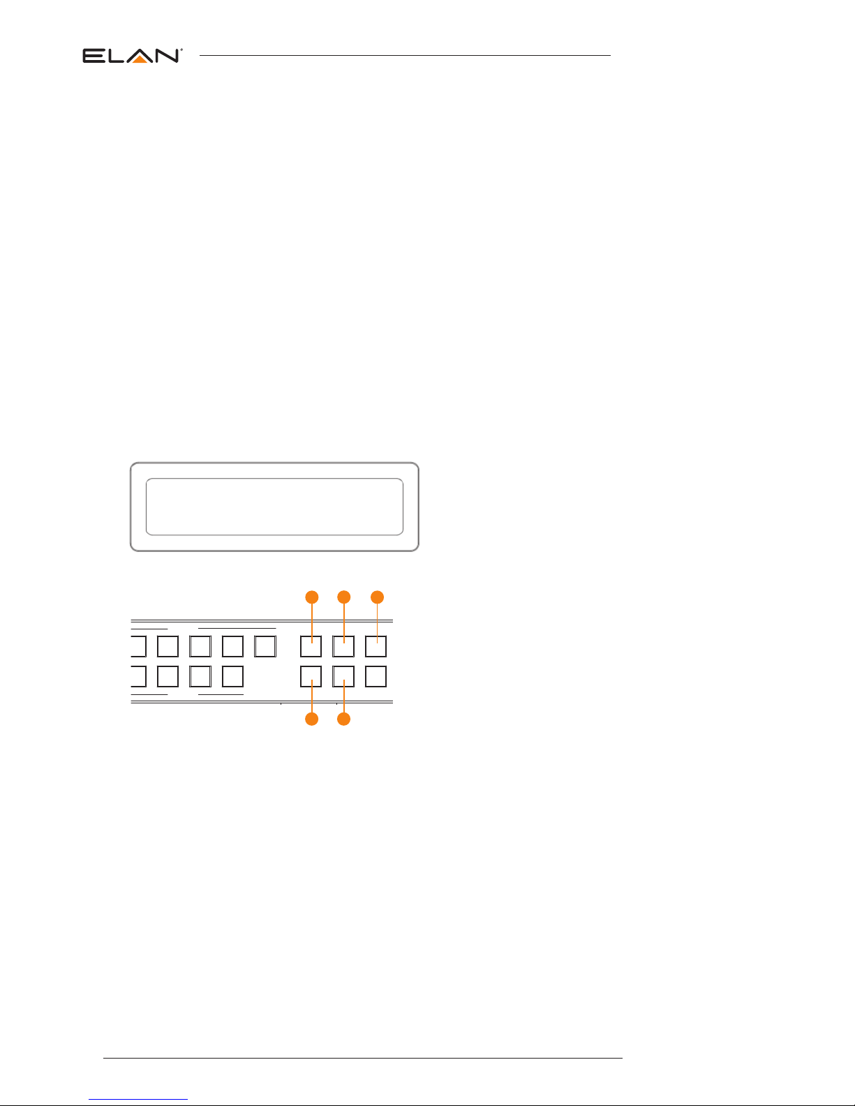
Front Panel
1
2 3 4 5 6 7 8 9
191817
16
151413
1 LCD display – Shows the status of
input/output selection, EDID etc.
2 IR receiver window.
3 Power LED indicator.
4 Power button – Press to power On/Off
the Matrix.
5 Matrix mode button - Press to activate
Matrix mode.
6 Video-Wall mode button - Press to
activate Video-Wall mode.
7 Multi-View mode button - Press to
activate Multi-View mode.
8 HDMI output selection button 1 to 4 - To
select the output from 1 to 4.
9 All button for HDMI outputs – All
outputs will work as one (Selects all
outputs).
q Menu button – Press to enter EDID set
mode (see page 5).
w Up selection button - Press to change
segment’s value.
e ESC – Press to quit EDID set mode.
r Lock indicator.
t Lock button – Press to lock the buttons
of the front panel.
y HDMI input selection button - Press to
individually change inputs 1-4 to HDMI.
u VGA input selection button - Press to
individually change inputs 1-4 to VGA.
i Input selection button 1 to 4 – Press to
select the input from 1 to 4.
o Selection button – Press to select
current setting.
p Down selection button – Press to
change segment’s value.
a Enter button – Press to confirm mode
selection or set EDID to specified INPUT
or copy EDID from specified OUTPUT to
specified INPUT.
1 IR inputs – 3.5mm stereo jack. Routes
IR to the current source selected IR
output. When using the EL-4KACCIR-CAB 5v-to-12v IR converter cable
ensure cable direction is correct.
2 IR outputs – 3.5mm mono jack –
Source specific routed IR.
3 VGA inputs with associated 3.5mm L/ R
Analog audio – Connect to VGA sources
NOTE: Either HDMI OR VGA signal type
must be assigned per source input.
Both video inputs cannot be active at
the same time.
4 TCP/IP (RJ45) – Connect to LAN for
TCP/IP control of Matrix or control by
built-in Web-GUI interface.
5 RS-232 port – For control of the Matrix
switcher from PC or control processer.
6 HDMI output – Connect to HDMI
displays.
7 HDMI inputs – Connect to HDMI
sources.
8 HDMI active connection LED - Lit when
active HDMI connection is connected.
9 IR input for matrix control – For hard
wired IR connection. Connect to EL AN
control processor.
q Power port – Use supplied 12V 3A
DC adaptor to power.
w Power switch - Turn Matrix On/Off
10 11 12
20
11
Panel Descriptions
Page 5
05
contact techsupport@ elanhomesystems.com
EL-4KM-VW44 USER MANUAL
EL-4KM-VW44
1
2 3 4
1
2 3 4
IR Input IR Output
RS-232
TCP/IP
1
2 3 4 1 2 3 4
HDMI Output HDMI Input
VGA 1
VGA 2
VGA 3
VGA 4
L/R 1
L/R 2
L/R 3
L/R 4
IR Ext.
Off
On
VGA Input
12V
3A
VideoMatrix
1 2 3 4
IR
Power
Lock
Matrix Video-Wall Multi-View
HDMI
VGA
Input
Output
All
Menu Up Esc
Select Down Enter
4
VGA 4
L/R 3
L/R 4
IR Ext.
Off
On
12V
3A
Input
Output
All
Menu Up Esc
Select Down Enter
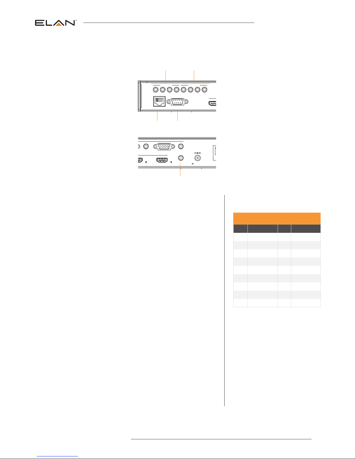
The EL-4KM-VW44 main communication ports are located on the rear panel and includes the following connections:-
Connections:
A. IR Input (3.5mm stereo jack) for routed IR pass-through to the associated
source output emitters.
B. IR Output (3.5mm mono jack) for routed IR control of source equipment
C. TCP/IP – For control of the Matrix (RJ45 Connector)
D. RS-232 – For control of the Matrix (9 pin serial connection)
E. Global IR Input 3.5mm stereo jack - For control of the Matrix Switcher
TCP/IP
The ELAN EL-4KM-VW44 Matrix can be controlled via TCP/IP.
For the full list of protocols please see ‘RS-232 and Telenet Commands’ located at the
rear of this manual.
The EL-4KM-VW44 Matrix features a built-in web browser user interface allowing control
and configuration of the matrix. For further details please see page 21 ‘Web Browser
User Interface’.
A ‘Straight-through’ RJ45 patch lead should be used.
RS-232 2-Way
The ELAN EL-4KM-VW44 can be controlled via a 9-pin serial cable.
For the full list of protocols please see ‘RS-232 and Telenet Commands’ located at the
rear of this manual.
Details of RS-232 pin assignment and communication are adjacent. Please note that
depending on your control device serial port pin configuration you may require either a
‘Straight’ RS-232 cable or ‘Null-modem’ type.
Control Ports
ELAN RS-232 REMOTE CONTROL
CONSOLE
PIN Assignment PIN Assignment
1 NC 1 NC
2 Tx 2 Rx
3 Rx 3 Tx
4 NC 4 NC
5 GND 5 GND
6 NC 6 NC
7 NC 7 NC
8 NC 8 NC
9 NC 9 NC
Baud Rate: 57600 bps
Data Bit: 8-bit
Parity: None
Stop Bit: 1-bit
Flow Control: None
A B
C D
E
Page 6
EL-4KM-VW44 USER MANUAL
06
www.elanhomesystems.com
To change the EDID value for source inputs using the Matrix front panel buttons press the following:-
A. Press MENU button.
B. Panel will display ‘EDID settings’. Press SELECT button
C. Select the input you wish to fix the EDID on (1-4) or select ‘All’. Use UP/DOWN buttons to toggle selection and ENTER button to confirm.
D. Select video resolution required (1080p, 1080i, DVI etc). Use UP/DOWN buttons to toggle selection and SELECT button to confirm.
Options are standard EDID settings (DF00-DF04) or 'COPY' EDID from outputs 1-4.
E. Press the ESC button to exit.
1 2 3 4
Input
Output
All
Menu Up Esc
Select Down Enter
EDID: IN ALL DF00
HDMI: 1080P @ 60HZ
EDID Management - Global or individual input settings
The following characters show adjusting the EDID for ‘All’ inputs (Global). Current EDID value is DF00 (Default setting 0) which is 1080p @ 60Hz.
Matrix Front Panel Control
Turning On/Off HDMI outputs
It is possible to turn off each individual HDMI output using RS-232, TCP/ IP or Web GUI interface. This can be helpful when using panels with a
'signal sense' power on/off feature.
Please see page 17 for list of product RS-232 and Telnet commands.
Note: There is no indication on the front panel to inform users that the outputs of the Matrix have been turned off. If you are unsure of the status of
the zone outputs you can force all outputs back on in one of two ways:
• Powering OFF/ON the matrix. All outputs will be turned on when powered up.
• Zone outputs can be forced back on by pressing and holding ‘OUTPUT 1’ button on the front panel for 10 seconds. The matrix will reset and all
outputs will be turned back on.
B
A E
C/D
C/D
Page 7
07
contact techsupport@ elanhomesystems.com
EL-4KM-VW44 USER MANUAL
1 2 3 4
Matrix Video-Wall Multi-View
HDMI
VGA
Input
Output
All
Menu Up Esc
Select Down Enter
1 2 3 4
Matrix Video-Wall Multi-View
HDMI
VGA
Input
Output
All
Menu Up Esc
Select Down Enter
Matrix Mode
The following shows how to activate ‘Matrix’ mode and change source inputs.
Matrix Mode Selection
1. To enter ‘Matrix’ mode first press ‘MATRIX’ button .
To confirm selection press the ‘ENTER’ button.
Source Selection
2. To change source selection per HDMI output press the desired ‘OUTPUT’ button (1-4) or ‘ALL’.
3. Press desired source ‘INPUT’ button.
The display will show both the source input selected and if this is HDMI (H) or VGA (V) video type (see above).
Matrix Front Panel Control
Video Input Type Selection
The EL-4KM-VW44 allows you to switch between HDMI and VGA+ audio per source input. It is only possible to select either HDMI or VGA per
source and it is not possible to view both video types on the same input, I.E- You cannot select HDMI input 1 and VGA input 1 at the same time.
1. To change input video type first press ‘INPUT’ button (1-4).
2. The chosen input number will start to flash.
3. Press either the ‘HDMI’ or ‘VGA’ select button.
A. When HDMI is selected the letter ‘H’ will be displayed under the source input number.
B. When VGA is selected the letter ‘V’ will be displayed under the source input number.
IN 1 2 3 4
SRC H V H V
A B A B 1
MX 1 2 3 4
IN 2H 1H 3V 4H
C
A B
D
1
3
2
Understanding the display:
A. ‘MX’ shows that the products is in Matrix mode.
B. Indicates the output
C. Indicates the source input selected (1-4)
D. Indicates the video signal type (H or V). H = HDMI, V=VGA
Page 8

EL-4KM-VW44 USER MANUAL
08
www.elanhomesystems.com
Matrix Front Panel Control
Video Wall Mode
The following shows how to activate the ‘Video Wall’ mode, change screen layouts and change source inputs
Selecting Video Wall Mode:
1. To select Video Wall mode first press ‘Video Wall’ button
2. The display will change and the current screen layout configuration will begin to flash. You must select the required screen
configuration using the ‘UP’ or ‘DOWN’ buttons. The screen layouts are:
3. Press the ‘ENTER’ button to finalise the Video Wall configuration.
2 x 2 1 x 4 4 x 1
Understanding the display:
A. ‘VW’ shows that the products is in Video Wall mode.
B. Indicates the screen configuration currently selected.
C. * Indicates the current screen configuration shown is active.
D. [EN] is a reminder to press ‘ENTER’ button to finalise selection.
CHANGE MODE TO
A
VW 2X2 * [EN]
B C D
1
3
2
1 2 3 4
HDMI
VGA
Input
Output
All
Menu Up Esc
Select Down Enter
Page 9

09
contact techsupport@ elanhomesystems.com
EL-4KM-VW44 USER MANUAL
1 2 3 4
Matrix Video-Wall Multi-View
HDMI
VGA
Input
Output
All
Menu Up Esc
Select Down Enter
Matrix Front Panel Control
Video Wall Mode
Changing Source inputs when in Video Wall mode:
1. To change the source input selection first press ‘Video Wall’ button
The display will change showing the current screen layout configuration and input selected.
2. Press desired ‘INPUT’ button (1-4)
1
3
2
Changing Source input video types between HDMI and VGA when in Video Wall mode:
See page 7 - ‘Video input type selection’
Changing the screen configuration when in Video Wall mode:
1. To change screen configuration first press ‘Video Wall’ button
2. The display will change and the current screen layout configuration will begin to flash. You must select the required screen
configuration using the ‘UP’ or ‘DOWN’ buttons.
3. Press the ‘ENTER’ button to finalise selection.
1 2 3 4
Matrix Video-Wall Multi-View
HDMI
VGA
Input
Output
All
Menu Up Esc
Select Down Enter
1
2
Understanding the display:
A. ‘2 x 2’ shows that the current screen configuration selected/to be selected.
B. Indicates the source input currently selected.
C. Indicates the video signal type (H or V). H = HDMI, V=VGA
D. [EN] is a reminder to press ‘ENTER’ button to finalise the selection.
[IN 1-4] is a reminder of source inputs available.
VW: 2 x 2 [EN]
A
B C D
IN: 1 H [IN 1-4]
Page 10

EL-4KM-VW44 USER MANUAL
10
www.elanhomesystems.com
Matrix Front Panel Control
Multi-View Mode
The following shows how to activate the ‘Multi-View’ mode, change screen layouts and change source input selection.
When in Multi-View mode all HDMI outputs will display the same Multi-View selected layout.
Selecting Multi-View Mode:
1. To select Multi-View mode first press ‘Multi-View’ button
2. The display will change and the current screen layout configuration will begin to flash. You must select the required Multi-View
screen configuration (0-9) using the ‘UP’ or ‘DOWN’ buttons. The screen layouts are:
CHANGE MODE TO
A
3. Press the ‘ENTER’ button to finalise the Multi-View configuration.
Understanding the display:
A. ‘MV’ shows that the products is in Multi-View mode.
B. Indicates the screen configuration currently selected.
C. * Indicates the current screen configuration shown is active.
D. [EN] is reminder to press ‘ENTER’ button to finalise selection.
* Please note that 'layout 0' is the default configuration
Layout 9 has been designed for use with VGA source inputs that are not standard 16:9 size
MV LAYOUT 2 * [EN]
B C D
Layout 0 Layout 1 Layout 2 Layout 3
Layout 4 Layout 5 Layout 6 Layout 7
Layout 8 Layout 9
= Window 1
= Window 2
= Window 3
= Window 4
1
3
2
1 2 3 4
HDMI
VGA
Input
Output
All
Menu Up Esc
Select Down Enter
Page 11

11
contact techsupport@ elanhomesystems.com
EL-4KM-VW44 USER MANUAL
Matrix Front Panel Control
Multi-View Mode
Changing Source inputs when in Multi-View mode:
The ‘OUTPUT’ buttons are used to adjust the Window layouts when in Multi-View mode. Output 1 = Window 1, Output 2 = Window 2 etc...
Please see page 10 for Window positions per layout.
To allocate a source input to a particular Window:-
1. Press the desired ‘OUTPUT/Window’ button (1-4).
2. Press desired source ‘INPUT’ button .
The display will show both the source input selected and if this is HDMI (H) or VGA (V) video type.
Note: The master Window/output is always Window 1. The source allocated for Window 1 cannot be replicated on any other output Window.
The secondary Windows (2-4) can display the same source input as each other should this be required.
Should you try to allocate the same source that is selected for Window 1 to another Window (2-4) an error message will appear.
Changing Source input video types between HDMI and VGA when in Multi-View mode:
See page 7 - ‘Video input type selection’
MV8: 1M 2 3 4
A
1
2
C D
Understanding the display:
A. ‘MV8’ shows that the product is in Mult-View mode and in the above example, layout 8 has been selected.
B. ‘M’ indicates that this is the main Window/Output
C. Indicates the Source input selected
D. Indicates the video signal type (V or H). H = HDMI, V=VGA
IN: 1 H 2H 3V 4H
B
1 2 3 4
HDMI
VGA
Input
Output
All
Menu Up Esc
Select Down Enter
Page 12

EL-4KM-VW44 USER MANUAL
12
www.elanhomesystems.com
The ELAN range of HDMI matrix products include multiple options for control and routing of IR.
IMPORTANT: The ELAN HDMI Platinum, Matrix, & HDBaseT product lines utilize 5 volts to power an IR Receiver on the IR Input and
include an EL-4KACC-IR-CAB, 3.5mm Mono to 3.5mm Stereo 5v to 12v IR converter cable. This cable is required when using 12v IR
products from Xantech, Niles, and SpeakerCraft.
Each ELAN Matrix and HDBaseT receiver is supplied with all necessary IR hardware required and includes:
InfraRed Distribution
IR Control Cable - EL-4KACC-IR-CAB
ELAN IR Control cable 3.5mm Mono to 3.5mm Stereo for linking
third party IR Receivers to ELAN Platinum, Matrix, and HDBaseT
HDMI Series products.
Compatible with 12v IR third party products.
Note: Cable is directional as indicated
IR Receiver - Stereo 3.5mm
Signal
Power
Ground
Infrared 3.5mm Pin-Out
IR Emitter - Mono 3.5mm
Signal
Ground
Page 13

13
contact techsupport@ elanhomesystems.com
EL-4KM-VW44 USER MANUAL
NOTE: THE BUTTON PRESS SEQUENCE SHOULD BE FINISHED IN 5 SECONDS,
OTHERWISE THE OPERATION IS DISCARDED
Infrared Remote Control
MODE SELECTION
A Switches between Matrix modes:
MX - Matrix mode
VW - Video Wall mode
MV - Multi-View mode
HDMI/VGA INPUT TYPE SELECTION
B Inputs 1-4 can be assigned as EITHER
HDMI or VGA video. This selection can be
acheived for each input.
HDMI selection - Press an input
button followed by the HDMI button.
VGA selection - Press an input
button followed by the VGA button.
OUTPUT AND INPUT SELECTION
C Selects the zone OUTPUT you wish to
change the source on (Numbers 1 - 4
correspond to the zone outputs 1 - 4)
B Selects the source INPUT you wish to
change on the selected zone (Numbers 1
- 4 correspond to the source inputs 1 - 4)
EXAMPLE
To switch source 2 to zone 4 you would
press 4 in the output section (C) followed by
pressing 2 in the Input section (B).
ALL button: The all button selects all the
inputs or outputs in its corresponding box.
Example: (The “All” button in the Output box
selects all the zones so all zones will change
to what source input is selected next).
EDID SET UP
The EL-4KM-VW44 provides a comprehensive
range of EDID settings. Below are three
examples of how to deploy the desired EDID
setting when using the supplied remote.
1. Fix EDID to an Input or ALL inputs:
Press the desired video resolution
button (1080i / 1080p etc), then select
the source input you want this EDID
information allocated to by pressing the
INPUT 1 – 4 or the ALL button
2. Copy EDID of Output-X to an Input
or ALL: Press the COPY but-ton then
select the OUTPUT you wish to copy the
EDID information from, then select the
source input you want to copy this EDID
to by selecting the INPUT 1-4 or the ALL
button.
3. User defined EDID to an Input or ALL
inputs: Press USER1 / USER2 button
then select the source you wish to assign
this EDID to by select-ing INPUT 1-4 or
the ALL button
B
C
D
A
Page 14

EL-4KM-VW44 USER MANUAL
14
www.elanhomesystems.com
EDID (Extended Display Identification Data) is a data structure that is used between a display and a source. This data is
used by the source to find out what audio and video resolutions are supported by the display then from this information the
source will discover what the best audio and video resolutions need to be outputted.
While the objective of EDID is to make connecting a digital display to a source a simple plug and play procedure issues do
arise when multiple displays or video matrix switching is introduced because of the increased number of variables.
By pre-determining the video resolution and audio format of the source and display device you can reduce the time need
for EDID hand shaking thus making switching quicker and more reliable.
Configuration of the EDID settings can be achieved in one of three ways:
1 Via the Web GUI
2 Using Matrix Front Panel Buttons (For further details see page 6)
3 Using Supplied ELAN Matrix IR Remote Control (For further details see page 13)
EDID Control
Page 15

15
contact techsupport@ elanhomesystems.com
EL-4KM-VW44 USER MANUAL
Application Diagram
EL-4KM-VW44
IR Emitter
Link to source
IR Receiver
Link to control device
Laptop 1 Laptop 2
Display 2Display 1
Display 4Display 3
HDMI Output
TCPIP RS232
HDMI Input
DC 12VIR Ext.
1 2 3 4 1 2 3 4
On
L/R 4L/R 3L/R 2L/R 1VGA 1 VGA 2 VGA 3 VGA 4
SOURCE 01
SOURCE 02
SOURCE 03
SOURCE 04
ZONE 04
ZONE 03
ZONE 02
ZONE 01
MAXIMUM OF 4 SOURCES
Control Processor
VGA
Network Connection
HDMI
Stereo Audio
RS232
IR Cable
1 2 3 4
1
2
4
3
RS-232
Page 16

EL-4KM-VW44 USER MANUAL
16
www.elanhomesystems.com
Specifications
Video Input Connections: 4x HDMI Type A, 19-pin, female & 4x VGA
Video Output Connections: 4x HDMI Type A, 19-pin, female
Audio Input Connections: 4x Analogue audio 3.5mm stereo Jack
RS-232 serial port: DB-9, female
TCP/IP Control: RJ45, female
IR Input ports: 5 x 5v 3.5mm stereo jack
IR Output ports: 4 x 5v 3.5mm mono jack
Mounting kit included
Casing Dimensions (W x H x D): 440mm x 45mm x 180mm
Dimensions including connections (W x H x D): 440mm x 44mm x 187mm
Shipping Weight: 4.0kg
Operating Temperature: 32°F to 104°F (0°C to 40°C)
Storage Temperature : -4°F to 140°F (-20°C to 60°C)
Power Supply: 12V/3A DC
Package Contents:
• 1x EL-4KM-VW44
• 1x 12V/3A DC power supply (Type A, C, G & I Adaptors included)
• 1x Remote control
Remote Includes CR2025 battery
• 1x Mounting kit
• 4 x 5v-to-12v IR converter cables
• 1 x User manual
Maintenance
Clean this unit with a soft, dry cloth. Never use alcohol, paint thinner or benzene to clean this unit.
Page 17

17
contact techsupport@ elanhomesystems.com
EL-4KM-VW44 USER MANUAL
RS-232 and Telnet Commands
The ELAN EL-4KM-VW44 can be controlled via serial and TCP/IP. The following pages list all available serial commands for the EL-4KM-VW44
Matrix. Details of RS-232 pin assignment can be found on page 5.
Commonly used Serial commands:
There are several commands that are commonly used for control and testing:-
STATUS Status will give feedback on Matrix such as zones on, type of connection etc
PON Power on
POFF Power off
OUTxxON (xx is the zone number you wish to turn on)
Example:- OUT01ON (This would turn output one back on)
OU Tx xFRyy (xx is the zone out, yy is the input)
Example:- OUT01FR04 (This would switch output 1 to source input 4)
Common Mistakes
• Carriagereturn–Someprogramsdonotrequirethecarriagereturnwhereasotherwillnotworkunlesssentdirectlyafterthestring.Inthe
case of some Terminal software the token <CR> is used to execute a carriage return. Depending on the program you are using this token
maybe different. Some other examples that other control systems deploy include \r or 0D (in hex)
• Spaces–ELANcommandsdonotrequirespacebetweencommandsunlessspecied.Theremaybesomeprogramsthatrequirespacingin
order to work.
- How the string should look is as follows OUT01ON
- How the string may look if spaces are required: OUT{ Space}01{Space}ON
• Baudrateorotherserialprotocolsettingsnotcorrect-pleaseseePage5forMatrixsettings
Page 18

EL-4KM-VW44 USER MANUAL
18
www.elanhomesystems.com
RS232 COMMAND DESCRIPTION
? Print Help Information
HELP Print Help Information
STAT US Print System Status And Port Status
PON Power On, System Run On Normal State
POFF Power Off, System Run On Power Save State
IRON/OFF Set System IR Control On Or Off
KEYON/OFF Set System KEY Control On Or Off
DBGON/OFF Set Debug Mode On Or Of f
BEEPON/OFF Set Onboard Beep On Or Off
RESET
RESE T ALL
Reset System To Default Setting (Should Type “Yes” To Confirm, “No” To Discard)
Reset System And Network To Default Setting
OUTxxON/OFF
Set OUTPUT:xx On Or Off
xx= 00: Select All OUTPUT Ports
xx= [01...04]: Select One OUTPUT Port
OU Tx xFRy y
Set OUTPUT:xx From INPUT:yy
xx= 00: Select All OUTPUT Ports
xx= [01...04]: Select One OUTPUT Port
yy=[ 01...04]: Select One INPUT Port
EDIDxxCPyy
Copy EDID from output (yy) to input (xx )
Both yy & x x can be set individually ( 01-08) or as ALL (00)
EDIDxxDFzz
Set Input:xx EDID To Default EDID:zz
zz= 00 : HDMI 1080p @60Hz, Audio 2CH PCM
zz= 01: HDMI 1080i @60Hz, Audio 2CH PCM
zz= 02: DVI 1920x1080@ 60Hz, Audio None
zz= 03: DVI 1280x1024@60Hz, Audio None
zz= 04: DVI 1280x720@ 60Hz, Audio None
zz= 05: User EDID 1
zz= 06: User EDID 2
zz= 07: GUI Download EDID
OUTMODEmm
Set Output mode:
mm = MX (matrix)
mm = MV (multi-view)
mm = VW (video wall)
mm = MV01, MV02 etc (multi-view layout 1, layout 2 etc)
mm = MV01, MV02 etc (multi-view layout 1, layout 2 etc)
mm = VW22 (video wall 2x2 ), V W41 (video wall 4x1), VW14 (video wall 1x4 )
OUTMVFRyy Set Multi-View Main window (window 1) from input yy=[01...04]: Select One INPUT Port
OUTVWFRyy Set Video Wall Output from input yy ( 01-04)
OUTxxVCLbb
OU Tx xVC Rbb
OUTxxVCTbb
OU Tx xVC Bbb
Pixel shift when in Video Wall mode
xx = Output port ( 01-04 or 00 for all outputs)
VCL = Left border
VCR = Right border
VCT = Top border
VCB = Bottom border
bb = Pixel shift ( 00-100)
INxxFRyy
Set input video type to HDMI or VGA
xx = Input port (01-04 or 00 for all inputs)
yy = HDMI (from HDMI signal)
yy = VGA (from VG A signal)
MVAU Daa
Multi-View audio output from input aa
aa = 01-04 (inputs)
aa = 00 (audio will follow output/window 1)
RS-232 and Telnet Commands (Continued)
RS-232
Page 19

19
contact techsupport@ elanhomesystems.com
EL-4KM-VW44 USER MANUAL
Infrared Commands
4X4 MATRIX PRODUCTS NEC IR: CUSTOMER CODE 1898 HEX IR
POWER 14
0000 0069 0000 002a 0150 00a8 0015 0015 0015 0015 0015 0015 0015 003f 0015 003f
0015 0015 0015 0015 0015 003f 0 015 0015 0015 0015 0015 0015 0015 003f 0015 003f
0015 0015 0015 0015 0015 0015 0015 0015 0015 0015 0015 003f 0015 0015 0015 003f
0015 0015 0015 0015 0015 0015 0015 003f 0015 003f 0 015 0015 0015 003f 0015 0015
0015 003f 0015 003f 0015 003f 0015 05d3
POWER OFF 46
0000 006D 0000 0022 0157 00AC 0016 0016 0016 0016 0016 0016 0016 0041 0016
0041 0016 0016 0016 0016 0016 0016 0016 0016 0016 0016 0016 0016 0016 0041 0016
0041 0016 0016 0016 0016 0016 0041 0016 0016 0016 0041 0016 0041 0016 0016 0016
0016 0016 0016 0016 0041 0016 0016 0016 0041 0016 0016 0016 0016 0016 0041 0016
0041 0016 0041 0016 0016 0016 0041 0016 0689
MATRIX MODE 09
0000 0069 0000 002a 0150 00a8 0015 0015 0015 0015 0015 0015 0015 003f 0015 003f
0015 0015 0015 0015 0015 003f 0 015 0015 0015 0015 0015 0015 0015 003f 0015 003f
0015 0015 0015 0015 0015 0015 0015 003f 0015 0015 0015 0015 0015 003f 0015 0015
0015 0015 0015 0015 0015 0015 0015 0015 0015 003f 0015 003f 0 015 0015 0015 003f
0015 003f 0015 003f 0015 003f 0015 05d3
VIDEO-WALL MODE 1d
0000 0069 0000 002a 0150 00a8 0015 0015 0015 0015 0015 0015 0015 003f 0015 003f
0015 0015 0015 0015 0015 003f 0 015 0015 0015 0015 0015 0015 0015 003f 0015 003f
0015 0015 0015 0015 0015 0015 0015 003f 0015 0015 0015 003f 0 015 003f 0015 003f
0015 0015 0015 0015 0015 0015 0015 0015 0015 003f 0015 0015 0015 0015 0015 0015
0015 003f 0015 003f 0015 003f 0015 05d3
MULTI-VIEW MODE 1f
0000 0069 0000 002a 0150 00a8 0015 0015 0015 0015 0015 0015 0015 003f 0015 003f
0015 0015 0015 0015 0015 003f 0 015 0015 0015 0015 0015 0015 0015 003f 0015 003f
0015 0015 0015 0015 0015 0015 0015 003f 0015 003f 0 015 003f 0015 003f 0015 003f
0015 0 015 0015 0 015 0015 0 015 00 15 0 015 0015 00 15 0 015 0015 00 15 0 015 0015 0 015
0015 003f 0015 003f 0015 003f 0015 05d3
INPU T 1 19
0000 0069 0000 002a 0150 00a8 0015 0015 0015 0015 0015 0015 0015 003f 0015 003f
0015 0015 0015 0015 0015 003f 0 015 0015 0015 0015 0015 0015 0015 003f 0015 003f
0015 0015 0015 0015 0015 0015 0015 003f 0015 0015 0015 0015 0015 003f 0015 003f
0015 0015 0015 0015 0015 0015 0015 0015 0015 003f 0015 003f 0 015 0015 0015 0015
0015 003f 0015 003f 0015 003f 0015 05d3
INPU T 2 1b
0000 0069 0000 002a 0150 00a8 0015 0015 0015 0015 0015 0015 0015 003f 0015 003f
0015 0015 0015 0015 0015 003f 0 015 0015 0015 0015 0015 0015 0015 003f 0015 003f
0015 0015 0015 0015 0015 0015 0015 003f 0015 003f 0 015 0015 0015 003f 0015 003f
0015 0015 0015 0015 0015 0015 0015 0015 0015 0015 0015 003f 0015 0015 0015 0015
0015 003f 0015 003f 0015 003f 0015 05d3
INPU T 3 11
0000 0069 0000 002a 0150 00a8 0015 0015 0015 0015 0015 0015 0015 003f 0015 003f
0015 0015 0015 0015 0015 003f 0 015 0015 0015 0015 0015 0015 0015 003f 0015 003f
0015 0015 0015 0015 0015 0015 0015 003f 0015 0015 0015 0015 0015 0015 0015 003f
0015 0015 0015 0015 0015 0015 0015 0015 0015 003f 0015 003f 0 015 003f 0015 0015
0015 003f 0015 003f 0015 003f 0015 05d3
INPU T 4 15
0000 0069 0000 002a 0150 00a8 0015 0015 0015 0015 0015 0015 0015 003f 0015 003f
0015 0015 0015 0015 0015 003f 0 015 0015 0015 0015 0015 0015 0015 003f 0015 003f
0015 0015 0015 0015 0015 0015 0015 003f 0015 0015 0015 003f 0 015 0015 0015 003f
0015 0015 0015 0015 0015 0015 0015 0015 0015 003f 0015 0015 0015 003f 0015 0015
0015 003f 0015 003f 0015 003f 0015 05d3
HDMI SOURCE SELECT ION 17
0000 006D 0000 0022 0157 00AC 0016 0016 0016 0016 0016 0016 0016 003F 0016 003F
0016 0016 0016 0016 0016 0016 0016 0016 0016 0016 0016 0016 0016 003F 0016 003F
0016 0016 0016 0016 0016 003F 0016 003F 0016 003F 0016 003F 0016 0016 0016 003F
0016 0016 0016 0016 0016 0016 0016 0016 0016 0016 0016 0016 0016 003F 0016 0016
0016 003F 0016 003F 0016 003F 0 016 0689
VGA SOURCE SELECTION 12
0000 006D 0000 0022 0157 00AC 0016 0016 0016 0016 0016 0016 0016 003F 0016 003F
0016 0016 0016 0016 0016 0016 0016 0016 0016 0016 0016 0016 0016 003F 0016 003F
0016 0016 0016 0016 0016 003F 0016 0016 0016 003F 0016 0016 0016 0016 0016 003F
0016 0016 0016 0016 0016 0016 0016 003F 0016 0016 0016 003F 0016 003F 0016 0016
0016 003F 0016 003F 0016 003F 0 016 0689
OUTPUT 1 50
0000 0069 0000 002a 0150 00a8 0015 0015 0015 0015 0015 0015 0015 003f 0015 003f
0015 0015 0015 0015 0015 003f 0 015 0015 0015 0015 0015 0015 0015 003f 0015 003f
0015 0015 0015 0015 0015 0015 0015 0015 0015 0015 0015 0015 0015 0015 0015 003f
0015 0015 0015 003f 0 015 0015 0015 003f 0015 003f 0015 003f 0015 003f 0015 0015
0015 003f 0015 0015 0015 003f 0015 05d3
OUTPUT 2 55
0000 0069 0000 002a 0150 00a8 0015 0015 0015 0015 0015 0015 0015 003f 0015 003f
0015 0015 0015 0015 0015 003f 0 015 0015 0015 0015 0015 0015 0015 003f 0015 003f
0015 0015 0015 0015 0015 0015 0015 003f 0015 0015 0015 003f 0 015 0015 0015 003f
0015 0015 0015 003f 0 015 0015 0015 0015 0015 003f 0 015 0015 0015 003f 0015 0015
0015 003f 0015 0015 0015 003f 0015 05d3
Page 20

EL-4KM-VW44 USER MANUAL
20
www.elanhomesystems.com
Infrared Command
OUTPUT 3 48
0000 0069 0000 002a 0150 00a8 0015 0015 0015 0015 0015 0015 0015 003f 0015 003f
0015 0015 0015 0015 0015 003f 0 015 0015 0015 0015 0015 0015 0015 003f 0015 003f
0015 0015 0015 0015 0015 0015 0015 0015 0015 0015 0015 0015 0015 003f 0015 0015
0015 0015 0015 003f 0 015 0015 0015 003f 0015 003f 0015 003f 0015 0015 0015 003f
0015 003f 0015 0015 0015 003f 0015 05d3
OUTPUT 4 4a
0000 0069 0000 002a 0150 00a8 0015 0015 0015 0015 0015 0015 0015 003f 0015 003f
0015 0015 0015 0015 0015 003f 0 015 0015 0015 0015 0015 0015 0015 003f 0015 003f
0015 0015 0015 0015 0015 0015 0015 0015 0015 003f 0015 0015 0015 003f 0015 0015
0015 0015 0015 003f 0 015 0015 0015 003f 0015 0015 0015 003f 0015 0015 0015 003f
0015 003f 0015 0015 0015 003f 0015 05d3
ALL OUTPUTS 5e
0000 0069 0000 002a 0150 00a8 0015 0015 0015 0015 0015 0015 0015 003f 0015 003f
0015 0015 0015 0015 0015 003f 0 015 0015 0015 0015 0015 0015 0015 003f 0015 003f
0015 0015 0015 0015 0015 0015 0015 0015 0015 003f 0015 003f 0 015 003f 0015 003f
0015 0015 0015 003f 0 015 0015 0015 003f 0015 0015 0015 0015 0015 0015 0015 0015
0015 003f 0015 0015 0015 003f 0015 05d3
EDID 18
0000 006D 0000 0022 0157 00AC 0016 0016 0016 0016 0016 0016 0016 003F 0016 003F
0016 0016 0016 0016 0016 0016 0016 0016 0016 0016 0016 0016 0016 003F 0016 003F
0016 0016 0016 0016 0016 003F 0016 0016 0016 0016 0016 0016 0016 003F 0016 003F
0016 0016 0016 0016 0016 0016 0016 003F 0016 003F 0016 003F 0016 0016 0016 0016
0016 003F 0016 003F 0016 003F 0 016 0689
EDID 44
0000 006D 0000 0022 0157 00AC 0016 0016 0016 0016 0016 0016 0016 003F 0016 003F
0016 0016 0016 0016 0016 0016 0016 0016 0016 0016 0016 0016 0016 003F 0016 003F
0016 0016 0016 0016 0016 003F 0016 0016 0016 0016 0016 003F 0016 0016 0016 0016
0016 0016 0016 003F 0016 0016 0016 003F 0016 003F 0016 0016 0016 003F 0016 003F
0016 003F 0016 0016 0016 003F 0016 0689
DVI 1080 EDID 0f
0000 006D 0000 0022 0157 00AC 0016 0016 0016 0016 0016 0016 0016 003F 0016 003F
0016 0016 0016 0016 0016 0016 0016 0016 0016 0016 0016 0016 0016 003F 0016 003F
0016 0016 0016 0016 0016 003F 0016 003F 0016 003F 0016 003F 0016 003F 0016 0016
0016 0016 0016 0016 0016 0016 0016 0016 0016 0016 0016 0016 0016 0016 0016 003F
0016 003F 0016 003F 0016 003F 0 016 0689
DVI 1024 EDID 51
0000 006D 0000 0022 0157 00AC 0016 0016 0016 0016 0016 0016 0016 003F 0016 003F
0016 0016 0016 0016 0016 0016 0016 0016 0016 0016 0016 0016 0016 003F 0016 003F
0016 0016 0016 0016 0016 003F 0016 003F 0016 0016 0016 0016 0016 0016 0016 003F
0016 0016 0016 003F 0016 0016 0016 0016 0016 003F 0016 003F 0016 003F 0016 0016
0016 003F 0016 0016 0016 003F 0016 0689
DVI 720 EDID 0a
0000 006D 0000 0022 0157 00AC 0016 0016 0016 0016 0016 0016 0016 003F 0016 003F
0016 0016 0016 0016 0016 0016 0016 0016 0016 0016 0016 0016 0016 003F 0016 003F
0016 0016 0016 0016 0016 003F 0016 0016 0016 003F 0016 0016 0016 003F 0016 0016
0016 0016 0016 0016 0016 0016 0016 003F 0016 0016 0016 003F 0016 0016 0016 003F
0016 003F 0016 003F 0016 003F 0 016 0689
EDID COPY 1e
0000 006D 0000 0022 0157 00AC 0016 0016 0016 0016 0016 0016 0016 003F 0016 003F
0016 0016 0016 0016 0016 0016 0016 0016 0016 0016 0016 0016 0016 003F 0016 003F
0016 0016 0016 0016 0016 003F 0016 0016 0016 003F 0016 003F 0016 003F 0016 003F
0016 0016 0016 0016 0016 0016 0016 003F 0016 0016 0016 0016 0016 0016 0016 0016
0016 003F 0016 003F 0016 003F 0 016 0689
Page 21

21
contact techsupport@ elanhomesystems.com
EL-4KM-VW44 USER MANUAL
Web Browser Interface
The ELAN EL-4KM-VW44 matrix unit can be both controlled and configured using the in-built web-server.
The EL-4KM-VW44 Matrix must be connected to an active network router/switch and it is advised that the Matrix is given
a static IP address. You can configure the network settings of the Matrix using the Web Browser Interface (ELAN Matrix
products are shipped with the network set to DHCP)
Page 22

EL-4KM-VW44 USER MANUAL
22
www.elanhomesystems.com
FCC Notice
This equipment has been tested and found to comply with the limits for a Class B digital device, pursuant to part 15 of the FCC Rules. These
limits are designed to provide reasonable protection against harmful interference in a residential installation. This equipment generates, uses, and
can radiate radio frequency energy and, if not installed and used in accordance with the instructions, may cause harmful interference to radio
communications. However, there is no guarantee that interference will not occur in a particular installation. If this equipment does cause harmful
interference to radio or television reception, which can be determined by turning the equipment off and on, the user is encouraged to try to correct
the interference by one or more of the following measures:
• Reorient or relocate the receiving antenna.
• Increase the separation between the equipment and receiver.
• Connect the equipment into an outlet on a circuit different from that to which the receiver is connected.
• Consult the dealer or an experienced radio/TV technician for help.
CAUTION - changes or modifications not expressly approved by the party responsible for compliance could void the user’s authority to operate
the equipment.
CANADA, INDUSTRY CANADA (IC) NOTICES
This Class B digital apparatus complies with Canadian ICES-003.
Operation is subject to the following two conditions: (1) this device may not cause interference, and (2) this device must accept any interference,
including interference that may cause undesired operation of the device.
CANADA, AVIS D’INDUSTRY CANADA (IC)
Cet appareil numérique de classe B est conforme aux normes canadiennes ICES-003.
Son fonctionnement est soumis aux deux conditions suivantes : (1) cet appareil ne doit pas causer d’interférence et (2) cet appareil doit accepter
toute interférence, notamment les interférences qui peuvent affecter son fonctionnement.
CORRECT DISPOSAL OF THIS PRODUCT
This marking indicates that this product should not be disposed with other household wastes. To prevent possible harm to
the environment or human health from uncontrolled waste disposal, recycle it responsibly to promote the sustainable reuse of
material resources. To return your used device, please use the return and collection systems or contact the retailer where the
product was purchased. They can take this product for environmentally safe recycling.
Certifications
Page 23

23
contact techsupport@ elanhomesystems.com
EL-4KM-VW44 USER MANUAL
Notes
––––––––––––––––––––––––––––––––––––––––––––––––––––––––––––––––––––––––––––––––––––––
––––––––––––––––––––––––––––––––––––––––––––––––––––––––––––––––––––––––––––––––––––––
––––––––––––––––––––––––––––––––––––––––––––––––––––––––––––––––––––––––––––––––––––––
––––––––––––––––––––––––––––––––––––––––––––––––––––––––––––––––––––––––––––––––––––––
––––––––––––––––––––––––––––––––––––––––––––––––––––––––––––––––––––––––––––––––––––––
Page 24

10014817 Rev-C0, 04/2017
main:
1 (800) 472-5555 - US
1 (707) 283-5900 - International
1 (707) 283-5901 - Fax
tech support:
techsupport@elanhomesystems.com
web:
elanhomesystems.com
© 2017 ELAN® is a registered trademark of Core Brands, LLC.
 Loading...