

Page 1
12 CHANNEL DIGITAL POWER AMPLIFIER
INSTALLATION MANUAL AND USER'S GUIDE
COMPACT, POWERFUL,
AND VERY COOL
D1200/D1201
Page 2
Follow Information All operating and use information should be followed.
The safety and operating information should be
retained for future reference.
All warnings on the unit and in the operating
instructions should be heeded.
Carts and Stands
Mounting of this unit should be done only by an
authorized installer.
.
Ventilation
This unit should be situated so that its location or position does not interfere with proper ventilation.
This unit should nev er be placed near or over a
radiator or heat register. This unit should not be placed in a built-in installation such as a bookcase or cabinet that may impede the flow of air through the ventilation openings.
Do not rack mount two or more amplifiers on top of each other without either forced-air ventilation or one rack space (1.75") between each unit.
Non-Use Periods Units that are left unattended and unused for long periods of time should be unplugged from the wall outlet.
Power Sources This unit should be connected to a power supply only of the type described in the operating instructions or as marked on each unit. If you are
not sure of the type of power supply to your home, consult your authorized ELAN dealer or local power company.
Grounding or Polarization
These audio products are equipped with a grounding-type alternating-current line plug. This plug will fit only into a grounding-type power receptacle. This is a safety feature. If the plug receptacle does not fit, contact an electrician to replace your obsolete receptacle. Do not defeat the safety
purpose of the grounding-type plugs.
Water and Moisture
To reduce the risk of electric shock or fire, these appliances should not be used near water - for example, near a bathtub, washbowl,
kitchen sink, laundry tub, in a wet basement, or near a swimming pool.
Power Cord Protection
Power supply cords should be routed so that they are not likely to be walked on or pinched by items placed upon or against
them, paying particular attention to cords at plugs, convenience receptacles, and the point where they exit from the appliances
.
Do not damage or deform the power supply cord. If it is damaged or deformed, it may cause electric shock or fire when used. Whe
n removing from the wall outlet, be sure to
remove by holding the plug attachment and not by pulling the cord.
Cleaning Unplug this audio product from the wall outlet before cleaning. Do not use liquid or aerosol cleaners. Use a damp cloth for cleaning
Overloading Do not overload wall outlets and extension cords, as this could result in fire or electric shock.
Object and Liquid Entry Never insert objects of any kind through the openings of these appliances, as they may touch dangerous voltage points or
short-out parts that could result in a fire or electric shock. Care should be taken so that objects do not fall and liquids are not spilled into the appliance through openings in the
enclosure.
Servicing Do not attempt to service these appliances yourself, as opening or removing covers may expose you to dangerous voltage or other hazards. Refer all ser-
vicing to qualified service personnel.
Damage Requiring Service These appliances should be serviced by qualified service personnel when:
A power supply cord or a plug has been damaged or
If liquid has been spilled into the appliance or objects have fallen into the appliance or
The appliance has been exposed to water or moisture or
The appliance does not appear to operate normally or exhibits a marked change in performance or
The appliance has been dropped or the enclosure damaged.
Replacement Parts When replacement parts are required, be sure the service technician has used replacement parts
specified by the manufacturer or that have the same characteristics as the original part. Unauthorized substitutions may result in fire,
electric shock, or other hazards.
Safety Check Upon completion of any service or repairs to this audio product, ask the service technician to perform safe-
ty checks to determine that the audio product is in proper operating condition.
Lightning For added protection for these audio products during an electrical storm, or when they are left unattended and
unused for long periods of time, unplug them from the wall outlet and disconnect the antenna or cable system. This will prevent damage
to the audio products due to lightning and power-line surges.
IMPORTANT SAFETY
INFORMATION
9700721
HOME SYSTEMS WITH AUDIO AND/OR
VIDEO CONTROL CAPABILITIES
ETL LISTED PRODUCT
CONFORMS TO UL STD 6500.
AUDIO/VIDEO AND MUSICAL INSTRUMENT
APPARATUS FOR HOUSEHOLD, COMMERCIAL,
AND SIMILAR USE.
ETL LISTED PRODUCT.
CONFORMS TO CAN/CSA E65-94.
D1200/D1201 INSTALLATION MANUAL & USER'S GUIDE ELAN HOME SYSTEMS
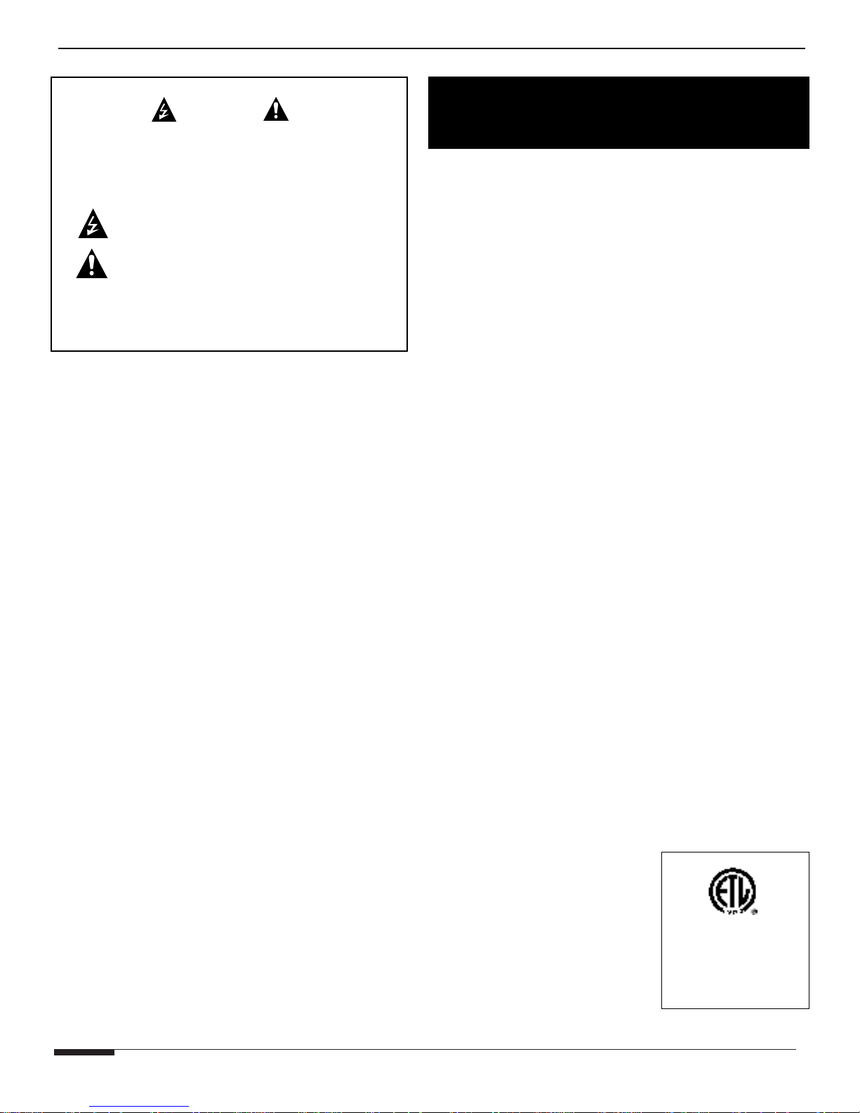
WARNING
RISK OF ELECTRIC SHOCK
DO NOT OPEN
CAUTION: TO REDUCE THE RISK OF ELECTRIC SHOCK, DO NOT
REMOVE COVER (OR BACK). NO USER SERVICEABLE PARTS INSIDE.
REFER SERVICING TO QUALIFIED SERVICE PERSONNEL.
The lightning flash with arrowhead symbol within an equilateral triangle
is intended to alert the user to the presence of uninsulated "dangerous
voltage" within the product's enclosure that may be of sufficient
magnitude to constitute a risk of electric shock to persons.
The exclamation point within an equilateral triangle is intended to alert
the user to the presence of important operating and maintenance
(servicing) instructions in the literature accompanying the device or
component.
WARNING: TO REDUCE THE RISK OF FIRE OR SHOCK,
DO NOT EXPOSE THIS APPLIANCE TO RAIN OR MOISTURE.
Read Information
Retain Information
Heed Information
Wall Mounting
All safety and operating information should be read
before the unit is operated.
This unit should be used with a stationary shelf. Do
not use any mobile carts.
Volume Controls Do not use volume controls rated for less than 100 Watts RMS. To do so can result in damage to the amplifier and the volume control.
*
*
*
*
*
PAGE 1
©ELAN Home Systems 2003 All rights reserved 07/03
Page 3

D1200/D1201 INSTALLATION MANUAL & USER'S GUIDE ELAN HOME SYSTEMS
TABLE OF CONTENTS
Safety Information .......................................................................................... 1
Table of Contents ........................................................................................... 2
Front View ...................................................................................................... 3
Introduction ................................................................................................... 4
I. Features ...................................................................................................... 4
Class T Explained.................................................................................. 5
II. Front Panel Function................................................................................... 7
A. Channel/Level Select Display ........................................................... 7
B. Signal/Clipping Indicators ................................................................. 7
C. Volume Adjustments ......................................................................... 8
D. Lockout.............................................................................................. 8
E. Factory Default................................................................................... 8
III. Connections .............................................................................................. 9
A. Safety Concerns ................................................................................ 9
B. System Types .................................................................................... 9
C. Speakers ..........................................................................................10
D. Using Volume Controls .....................................................................10
E. Trigger Inputs/Output ........................................................................11
IV. System Modes and Configurations .......................................................... 12
A. Universal Stereo Bus ...................................................................... 12
B. Mono vs. Stereo .............................................................................. 13
C. Mono Bus Modes ............................................................................ 13
V. Design & Applications ................................................................................14
A. Stand-Alone Systems .......................................................................14
1. Mono ........................................................................................14
2. Stereo ......................................................................................15
B. Multi-Zone .........................................................................................16
1. Stand-Alone Multi-Zone ...........................................................16
2. ELAN S System........................................................................17
3. ELAN Z System........................................................................18
4. ELAN Z System Mono .............................................................19
5. ELAN HD System ................................................................... 20
VI. Troubleshooting ....................................................................................... 21
VII. Specifications.......................................................................................... 23
VII. Warranty ................................................................................................. 24
©ELAN Home Systems 2003 All rights reserved 07/03
PAGE 2
Page 4

Page 5

D1200/D1201 INSTALLATION MANUAL & USER'S GUIDE ELAN HOME SYSTEMS
INTRODUCTION
The ELAN D1200 Digital Power Amplifier has been designed from the ground up specifically for
custom installers to provide the ultimate solution for multi-room, whole-house applications. Twelve
channels of clean, powerful audio can be combined in dozens of different ways to suit virtually any
situation that may be encountered in whole-house distributed audio systems. The D1200 uses an
audio bus system that allows inputs and outputs to be combined in many ways without the use of
extraneous patch cables. ‘Class T’ Digital technology and ACE™ (Automatic Clip Eliminator™) allow
efficient use of power, ensuring clean, powerful audio at all volume levels in any application. Remote
triggers and turn-on circuits for each channel enables the installer to integrate this amplifier easily
with any ELAN multi-zone system or in stand-alone applications without additional ELAN equipment.
I. FEATURES
‘CLASS T’ DESIGN
‘Class T’ allows the D1200 to deliver its full rated power from all twelve channels simultaneously
and is 90% efficient so the amplifier does not waste energy producing excess heat.
TWELVE HIGH-POWER CHANNELS
Audio quality is greatly improved when plenty of power is applied to each speaker in
a multi-zone environment. Bass sounds better. Dynamic range is improved. Voices sound
full and rich. The D1200 provides 12 x 100 Watts @ 4 Ohms; ideal for virtually any distributed
audio system. ELAN uses an ultra-high efficiency torroidal transformer and 200,000 uF of bulk
storage capacitance to ensure plenty of power when it’s needed!
UNIVERSAL STEREO BUS
A-Bus and B-Bus inputs and outputs allow the amplifier to be configured in dozens of different
ways to meet the demands of large audio distribution systems. Channels can be assigned to
one of two audio busses in order to be split or combined according to situational demands.
Audio inputs can be A-BUS, B-BUS, Independent, Stereo, or Mono without the use of extraneous
patch cables. Additional amplifiers can be connected from the Bus outputs of the D1200 to
provide greater system expansion.
ACE™ (AUTOMATIC CLIP ELIMINATOR)
Microprocessor-controlled dynamic leveling circuit eliminates clipping without audio degradation
typical with traditional compressor-based clipping circuits. Each amplified output is continuously
monitored for signal clipping. Extremely fast transients are ignored but if ACE sees a consistent
clipping trend, it turns the respective channel down by one increment. This action is repeated
until no more clipping is detected. Once clipping is absent for five seconds, ACE will slowly and
unnoticeably begin to restore the original gain settings. This translates into accurate high quality
audio reproduction at all volume levels.
©ELAN Home Systems 2003 All rights reserved 07/03
PAGE 4
Page 6

D1200/D1201 INSTALLATION MANUAL & USER'S GUIDE ELAN HOME SYSTEMS
INDIVIDUAL REMOTE TRIGGER INPUTS/TRIGGER OUT
Six +12VDC Trigger Inputs allow each pair of channels to be powered up and muted
independently. +12VDC Trigger Output turns on and mutes additional amplifiers.
FRONT PANEL DISPLAY AND CONTROLS
High-visibility blue LED display and front panel Channel Select and Volume Adjustment controls
make setup easy. Blue Signal LEDS show when audio is present on each input. Red Clipping
LEDS indicate distortion, and make fine tuning the amplifier very straightforward. Five blue
LEDs fire downward to softly indicate Power status.
DIGITAL VOLUME LEVEL SET AND LOCKOUT
All channel volume levels are matched to within 0.3dB, making volume setup easy, accurate,
and repeatable. Volume settings are stored within the D1200's non-volatile memory upon
exiting setup. This means that settings are preserved even when a power outage occurs. A
special multi-button key press can be used to "Lock" the volume settings so that they can not
be tampered with. The user may view their settings when the system is locked, but is unable
to change them.
ADVANCED AMPLIFIER PROTECTION
Each channel of the D1200 is coupled to its respective output binding post via a high power
relay. If the processing circuitry senses a fault condition (over heating, shorted output, etc.)
It will completely disconnect the amplifier channel from the output load. Faulted conditions will
be indicated on the front panel. After finding and correcting the problem causing the fault
condition, simply power the unit OFF and back ON to restore operation.
RACK MOUNT ALUMINUM FRONT PANEL WITH RUGGED HANDLES (D1201)
Amplifier mounts securely to equipment racks. Handles are invaluable when moving, installing,
adjusting or servicing the unit.
CLASS T DIGITAL TECHNOLOGY EXPLAINED
The ultimate objective of any audio amplifier design is to make a high fidelity
high efficiency and high reliability. There are several basic audio power amp topologies
that have been developed to attain these objectives; Class-A, Class-B, Class-AB, ClassH, Class-G and Class-D are the most common. The D1200 utilizes proprietary Class-T
topology from Tripath™. Class T combines the best of several of these designs and
minimizes deficiencies in each design as well.
Class-A, Class-B and Class-AB amps have been around for over 50 years. Basically,
these classifications designate the amount of time that the amps output devices conduct
during one, full cycle of a periodic signal. Class-A amps are in a state of conduction 100%
of the time; Class-B amps have a complimentary pair of outputs, which are biased so that
each output is conducting only 50% of the time. Class-AB amps also have complimentary
output pairs but they are biased so that each output is conducting slightly more that 50%
of the time; this lowers crossover distortion. The vast majority of audio amps in use today
amp with
PAGE 5
©ELAN Home Systems 2003 All rights reserved 07/03
Page 7

D1200/D1201 INSTALLATION MANUAL & USER'S GUIDE ELAN HOME SYSTEMS
are Class-AB. A well-designed Class-AB amplifier has good linearity (high fidelity) and
poor efficiency (less than 50%). Class-H and Class-G are both voltage supply varying
techniques which are usually applied to Class-AB type, linear amplifiers. These
techniques give marginal improvement in efficiency at the cost of a more complex and
less reliable power supply.
Class-D amplifiers use output devices which switch on and off at a fixed frequency. This
frequency is usually more than ten times higher than the highest frequency to be
amplified. A passive filter reconstructs the wave form passing through the amplifier and
removes switching artifacts that distort sound. Class D amplifiers use output devices that
are either ON or OFF, never in a state of mid-conduction. This mid-conduction state is
what causes linear switching amplifiers to be as inefficient as they are (less than 50%
efficiency.) Class D amps approximately 85% efficient: a 35% increase!
As mentioned, each of these amplifier designs has drawbacks. Class D amps have
tendencies toward high distortion rates. Crossover distortion, ground bounce, and highfrequency artifacts create most of the distortion in these designs. Imperfectly matched
transistors lead to inexact ON/OFF timing results and crossover distortion issues. Ground
Bounce caused by high-current switching of the output transistors manifests itself as
noise on the audio output. In some Class D amplifiers, this high-frequency noise is not
completely filtered out, resulting in high frequency distortion.
CLASS T TECHNOLOGY-- WHY IT'S BETTER
Class T is a combination of Adaptive Digital Signal Processing and Spread Spectrum
Switching. This design takes the efficiency of a Class D design and combines it with the
fidelity of a Class AB amplifier by dramatically improving signal integrity. Class T offers
the following improvements over Class D:
1. Class D has a fixed switching input.
Class T has an adaptive switching frequency
which is dependent upon both input signal frequency and magnitude. Switching
artifacts are removed in this way, reducing distortion. The switching signal is
constantly being optimized to match the input signal in order to yield the highest
possible fidelity
2. Class D amplifiers have nominal
switching frequencies between 200kHz and
300kHz which creates artifacts in the 20 to 50kHz audio band. This can be heard
as audible noise. Class T amplifiers have nominal switching frequencies between
600kHz and 700kHz; artifacts from this frequency are not audible.
3. Class T design constantly monitors the out
put transistors and adaptively corrects
for variations between and within these transistors. The Class T design also
monitors and corrects for ground bounce that the transistors produce when
switching large currents.
4. Typical power efficiency with a Class T amp
lifier is 85% (unreachable by class A-B
amps,) Typical THD + Noise is less than 0.04% (unreachable by Class D amps.)
Truly the best of both worlds!
©ELAN Home Systems 2003 All rights reserved 07/03
PAGE 6
Page 8
D1200/D1201 INSTALLATION MANUAL & USER'S GUIDE ELAN HOME SYSTEMS
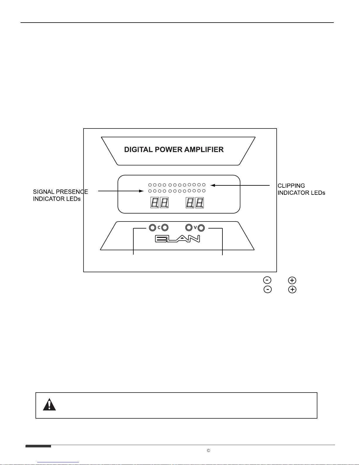
II. FRONT PANEL FUNCTIONS
A.CHANNEL SELECT DISPLAY/VOLUME ADJUSTMENT DISPLAY
The leftmost display on the front of the D1200 shows which channel is selected for
adjustment. Pressing C+ or C- will cycle through each individual channel. Once a
channel is selected, use V+ and V- buttons to adjust the channel’s Volume Up or Down
from 0 to 99 (50 is factory default). See VOLUME ADJUSTMENTS.
CHANNEL SELECT
BUTTONS
Select a Channel with C Buttons
Adjust Volume with V Buttons
VOLUME ADJUST
BUTTONS
C
V
B.SIGNAL/CLIPPING INDICATORS
There are twenty-four LEDs on the front panel of the D1200 designated for signal
presence and clipping indication. Twelve blue LEDs indicate when an audio signal is
present on each input. The left most blue LED is channel one, and the rightmost LED is
channel 12. Red LEDs are placed above the blue ones to indicate clipping for each
corresponding channel. Consistent red LEDs indicate over-saturation of the input
signal. Volume should be reduced for the affected channels. See VOLUME
ADJUSTMENTS.
THERE IS NO BENEFIT FROM TURNING THE AMPLIFIER'S VOLUME PAST
THE POINT WHERE THEY CAUSE THE RED CLIPPING LEDs TO LIGHT UP.
PAGE 7
ELAN Home Systems 2003 All rights reserved 07/03
Page 9

D1200/D1201 INSTALLATION MANUAL & USER'S GUIDE ELAN HOME SYSTEMS
C. VOLUME ADJUSTMENTS
Each amp channel can be individually adjusted from the front panel. Pressing the C
button will cycle thru all the inputs on the amplifier
can be adjusted independently. The C button
— both Left and Right channels
to the left cycles downward, the one on
the right cycles upward. When the desired channel is displayed on the front panel, use the
V buttons. Again, the
V button to the left lowers the volume for that channel, the one
on the right raises the volume. Set the levels
by lowering them all the way down, then raise
the volume of any keypads or volume controls to maximum. Slowly adjust volume up for this
channel until the red clipping LEDS start to light up, then drop the level one or two clicks. Follow
this procedure for all channels and the amplifier’s volume levels will be properly set up. Factory
default settings put all channel volume levels to
50. Please note: Whenever the Front Display
is illuminated (during volume adjustment, for example), ACE™ clipping elimination
circuitry is disabled.
TURNING THE VOLUME LEVEL PAST THE POINT OF
DISTORTION WILL NOT INCREASE THE VOLUME!
DIGITAL POWER AMPLIFIER
+
CHANNEL
-
+
-
VOLUME
SELECT A CHANNEL, THEN ADJUST THE VOLUME
D. LOCKOUT
The Lockout feature is designed to disable all front panel functions. Use this feature once the
system is fine tuned and ready-to-go. By locking the system’s front panel, prying hands cannot
ruin carefully set level adjustments or overdrive speakers.
To place the D1200 in Lockout Mode:
1. With the Front Display dark, Press C- and V- simultaneously.
2. Continue pressing C- and V-. The Front Display will show the Volume setting momentarily.
3. Four seconds later, the Front Display will read LOCH. Release the buttons.
4. Follow the same procedure to Unlock the D1200. This is a toggle command.
If the user tries to change settings while in Lockout Mode, the Front Display will read LC.
©ELAN Home Systems 2003 All rights reserved 07/03
PAGE 8
Page 10

D1200/D1201 INSTALLATION MANUAL & USER'S GUIDE ELAN HOME SYSTEMS
E. FACTORY DEFAULT
When your D1200 arrives, it is set to a FACTORY DEFAULT condition. At some point during the
life of this amplifier it may be necessary to put the unit back into Factory Default mode. If
this unit is moved to a different location or speaker type, load, or location are changed, the
FACTORY DEFAULT procedure should be used.
1. Turn the D1200 OFF using the rear Power Switch.
2. Turn the unit back ON. The Front Display will read
3. Press and hold C+, C-, V+, and V- (all the front panel buttons at once) while
is displayed.
4. The Front Display will read FAC dEF.
ELAN.
ELAN
The Factory default settings are:
• All channels Volume defaults to 50.
• Lockout feature is Disabled.
• ACE ™ Automatic Clip Eliminator is Enabled.
III. CONNECTIONS
A. SAFETY CONCERNS
Although the D1200 is extremely efficient and runs cool, ELAN reccommends placing this
amplifier in a well-ventilated area that allows heat to rise. Do not place the D1200
on the bottom of a large stack of equipment in an enclosed area.
This unit is HEAVY! Use caution when picking it up and make sure that whatever supports
this amplifier can hold fifty pounds (50 LBS) safely. Do not place the amplifier with the rear
panel of the unit on the ground. Damage to speaker binding posts can occur.
Use only grounded outlets when using this product. Making any modification to the power
cord could cause unsafe operation and will void the manufacturer's warranty. This amplifier
is very powerful and should have its own dedicated 15 Amp AC circuit.
ALL CONNECTIONS SHOULD BE MADE WITH THE AMPLIFIER
TURNED OFF AND UNPLUGGED FROM POWER. DAMAGE CAN
OCCUR TO EQUIPMENT IF IMPROPER CONNECTIONS ARE MADE!
B. SYSTEM TYPES
Zone Outputs are typically connected to the D1200s inputs when used with a multi-zone
controller. In a simple application, each stereo zone output goes into a Direct input—sending
left and right audio to the two speakers assigned to that particular zone. Zone outputs can be
Fixed (speaker outputs wide open and attenuated with volume controls,) or Variable (volume
is controlled at pre-amp level and requires no volume control.)
Source components in stand-alone installations should be connected using high-quality RCA-type
stereo interconnect cables. Make sure to verify whether a fixed-level or variable signal will be
used, and whether a volume control will be connected. Fixed level sources require Volume
Controls, Variable source typically will not. Most stand-alone systems will contain an A/V receiver,
a stereo receiver, or a preamp; seldom will a true source component (DVD, CD, Tape) be
connected directly to the D1200.
PAGE 9
©ELAN Home Systems 2003 All rights reserved 07/03
Page 11

D1200/D1201 INSTALLATION MANUAL & USER'S GUIDE ELAN HOME SYSTEMS
FOR SAFETY: ONLY USE VOLUME CONTROLS
RATED FOR 100 WATTS RMS OR HIGHER
C. SPEAKERS
Each speaker output of the D1200 is rated to handle a four ohm load. Speaker loads
below four ohms will cause the amplifier to go into a protection mode and cause undesirable
operation. Impedance matching volume controls can be used in situations where a four to eight
Ohm load cannot be maintained by wiring methods. The output of the D1200 exceeds some
Volume Control manufacturer's Wattage specifications. please ensure that any Volume
Controls used are rated for 100 Watts RMS or higher or damage to the Volume Control and/
or amplifier can occur. See USING VOLUME CONTROLS for additional information.
The five-way binding posts used on this product will accept bare speaker wire, banana plugs
(single or dual,) spade lugs, and pin connectors. Please ensure that adequate space is available
behind the amplifier to connect speaker terminations and that several inches of slack are available
on the speaker leads so that no tension is placed on these connections. Multiple speakers can be
connected to the speaker terminals through the use of banana plugs or other
Do not try to
Speaker leads should all be carefully trimmed to make sure that no stray wire strands touch.
Speaker wire should be 14 to 18 AW
longer runs require heavier gauge wire. When using larger than 16 AWG, spade lugs, pins, or
banana jacks must be used. Please maintain polar ity across all speaker leads in order to
preserve the “Phasing” of the speakers (audio quality) and to prevent damage to volume controls
that may be used in the system.
stuff multiple speaker leads into the five-way binding posts!
G twisted-pair speaker wir
e. As a general rule,
speaker terminators.
OUTPUTS SHOULD NEVER BE BRIDGED!
D. USING VOLUME CONTROLS
It is critical to use Volume Controls rated for 100 Watts RMS or higher when using theD1200
amplifier. Using Volume Controls rated for less than 100 Watts RMS can cause excessive
heating and damage to the Volume Control and to the D1200! Please remember that this
amplifier is four ohm stable. Impedance-match settings should take this into consideration.
THE USE OF UNDERRATED VOLUME CONTROLS POSES A FIRE RISK!
ELAN VS, VSO, VM, VMO, AND VSE VOLUME CONTROLS
ARE NOT COMPATIBLE WITH THE D1200 -- NEW HIGH
POWER VOLUME CONTROLS ARE BEING DEVELOPED
AND WILL BE AVAILABLE SOON.
Compatible ELAN Impedance Matching Volume Controls will be released soon.Please call
ELAN Technical Support if questions arise about compatibility of Volume Controls.
©ELAN Home Systems 2003 All rights reserved 07/03
PAGE 10
Page 12

D1200/D1201 INSTALLATION MANUAL & USER'S GUIDE ELAN HOME SYSTEMS
E. TRIGGER INPUTS/OUTPUT
Each channel pair of the D1200 has its own Remote Turn On/Muting circuit. Individual channel
pairs can be turned on or muted independently of any others. An ALL ON port allows the entire
amp to turn on and mute as one unit. The 12 Volt Trigger Out can be used to turn on other
equipment, additional amps, or to perform automated functions desired by the user. The Front
Display of the D1200 will show nA when a channel is in Mute.
TRIGGER INPUTS
A/V RECEIVER
TRIGGER OUT
D1200 TRIGGERS
D1200 TRIGGERS
TRIGGER
OUT
Single A/V Receiver Mutes/Turns
On all channels simultaneously
A/V RECEIVER
TRIGGER OUT
(6 RECEIVERS SHOWN)
D1200
TRIGGERS
ALL
ON
+12VDC
TRIG OUT
ALL
ON
+12VDC
TRIG OUT
TRIGGER
OUT
1/2 3/4 5/6
7/8
+12V TRIGGER INPUTS
TRIGGER
OUT
+12V TRIGGER INPUTS
TRIGGER
OUT
9/10
TRIGGER
OUT
1/2 3/4 5/6
9/10
11/12
TRIGGER
OUT
TRIGGER
OUT
7/8
11/12
ALL
ON
+12VDC
TRIG OUT
ZONE TRIGGER OUTPUTS
1
1/2 3/4 5/6
7/8
9/10
+12V TRIGGER INPUTS
2
3
11/12
S6 ZONE TRIGGER
OUTPUTS
4 5
6
Multi-Zone System (S6) Mutes/Turns
On each Pair of Channels Independently
TRIGGER OUTPUT
D1200
TRIGGER
OUT
TRIGGER IN
(ADDITIONAL AMP)
Multiple A/V Receivers Mute/Turn On
Each Pair of Channels Independently
TRIGGER INPUTS
ACCEPT 3 TO 24 VDC
PAGE 11
+12VDC
TRIG OUT
TRIGGER
IN
D1200 Turns On Additional Amplifier
With +12VDC Trigger Output
©ELAN Home Systems 2003 All rights reserved 07/03
Page 13

D1200/D1201 INSTALLATION MANUAL & USER'S GUIDE ELAN HOME SYSTEMS
IV. SYSTEM MODES & CONFIGURATIONS
A. UNIVERSAL STEREO BUS MODES
One of the primary design goals for the D1200 was ease of installation and flexibility. The
Universal Stereo Bus has achieved this goal by grouping desired channels together without
the use of additional RCA patch cables. By using the BUS A Dip switch settings, any number
of outputs can be tied together to the same input. Use of BUS B allows any number of other
channels to be grouped together Independently of BUS A. Any channel not configured to
BUS A or BUS B remains independent.
STEREO DIRECT MODE
STEREO
DIRECT IN
DIRECT IN DIP
SWITCH UP
(DEFAULT)
L
R
SRC/
ZONE
OUT
D1200
DIRECT
INPUT
L
R
L & R INPUTS TO L & R CHANNEL SPECIFIC SPEAKER OUTPUTS
STEREO BUS MODES
SRC/
ZONE
OUT
BUS A/
BUS B
INPUT
STEREO
BUS A
STEREO
BUS B
L
R
L
R
L & R SPEAKER OUTPUTS TO ALL BUS A (OR BUS B) CHANNELS
©ELAN Home Systems 2003 All rights reserved 07/03
OR
MOVE BUS A
OR B DIP
SWITCH TO
UP POSITION
PAGE 12
Page 14

D1200/D1201 INSTALLATION MANUAL & USER'S GUIDE ELAN HOME SYSTEMS
B. MONO VS STEREO
Typical listening areas in a whole-house system use two stereo speakers. In many instances,
however, one mono speaker is present, or two speakers are installed in a way in which true
stereo separation cannot exist. Mono configuration will sound better when speakers are installed
in areas that do not have a defined central listening area -- L shaped rooms, outdoor areas,
kitchens, bathrooms, or hallways, for example. Creative use of mono zones can enhance the
design flexibility and sound quality of a well-designed distributed audio system. The D1200 has
internally configuarable mono settings for each audio bus (BUS A and BUS B).
C. MONO BUS MODES
A 'Summed Mono' configuration can be derived from plugging both Left and Right RCA cables
from a stereo source into both Left and Right inputs of BUS A or BUS B. When BUS A MONO
(or BUS B MONO) is selected for a particular channel, both Left and Right speaker outputs will
play an identical mono signal. This effectively doubles the number of mono speakers outputs
available without Volume Controls!
PAGE 13
© ELAN Home Systems 2003 All rights reserved 07/03
Page 15

D1200/D1201 INSTALLATION MANUAL & USER'S GUIDE ELAN HOME SYSTEMS
V. DESIGN & APPLICATIONS
A. STAND-ALONE SYSTEM DESIGN AND APPLICATIONS
The D1200 can be configured in dozens of diferent ways in many types of applications. This
section describes "stand-alone" applications that do not utilize ELAN whole-house controllers.
These installations can take the form of anything from a basic home theater system in a living
room to a hyge ballroom with two dozen speakers! Most stand-alone applications will be
somewhere in-between and will be based on one or two models. The following examples show
basic methods of stand-alone system design. All of these examples are designed to be
expanded upon by adding additional inputs, outputs, volume controls, or speakers; even additional
additional D1200s. By using the Universal Stereo Bus features, stand-alone systems using the
D1200 can be as complex as the installer's imagination!
1. MONO SINGLE ZONE STAND-ALONE SYSTEM
8 OHM SPEAKERS
BUS A MONO
8 OHM SPEAKERS
Page 16

Page 17

B. MULTI-ZONE DESIGN/APPLICATIONS
The D1200 was designed with multi-zone systems in mind. By using an ELAN multi-zone
controller, certain amp channels are designated to specific zones of the house, each having
its own separate source selectability. The advantages of this system type are numerous:
1 Each area of the house can listen to a different audio source at the same time.
2. Source components do not have to be duplicated throughout the house (who wants to
buy twelve A/V receivers or DVD players?)
3. House-wide systems can interface easily (Page, Doorbell, Telemute).
4. System status can be conveyed throughout the house so that shared sources and zone
On/Off are evident (so that one person doesn't interrupt another person's movie, for example).
5. Separate zones can be personalized to allow only certain sources to be accessed or certain
features allowed or disallowed (Do Not Disturb, for example).
Page 18

2. MULTI-ZONE ELAN S SYSTEM
S6
S6 6 ZONE SYSTEM (ZONE 1 & 2 SHOWN)
ZONE 1 PREAMP OUT VARIABLE
ZONE 2 PREAMP OUT FIXED
ALL SPEAKERS IN ZONE 1 VOLUME RAMPS UP/DOWN USING KEYPAD
MAIN SPEAKERS IN ZONE 2 VOLUME RAMPS SEPARATELY USING HIGH POWER VOLUME CONTROLS
BUS A AND BUS B ENABLED
Page 19

3 ZONE Z SYSTEM
ALL ZONES SET TO VARIABLE
EACH ZONE RAMPS VOLUME UP/DOWN SEPARATELY W/ KEYPAD
ADD A 2nd Z630 TO CREATE A 6 ZONE SYSTEM
USE A TOTAL OF 4 Z 630s AND AN ADDITIONAL D1200 FOR 12 ZONES
Page 20

Page 21

Page 22

VI. TROUBLESHOOTING
SYMPTOM CAUSE SOLUTION
No Audio From One or More
Channels
2. Break/Short in Speaker Cable Check Continuity of Each Speaker
3. Speaker is Defective Swap with Known Good Speaker
4. RCA Patch Cable Defective Swap with Known Good Patch
6. All Dip Switches Down Move Appropriate Dip Switches UP
“NA” flashes on display, then
Volume setting
“Er” message displayed on
front panel
Audio “Hum”
Test AC Outlet Using Ground Tester
1. Loose/Bad peaker Cable S
Connection
5. Source not Sending Audio Verify Source is Powered Up and
7. Channel is in MUTE Make sure triggering device’s
8. Amplifier in Protection Mode Find short or low-impedance
1.Ground Potential Difference
Between Source Components
(Ground Loop)
Check Cable Ends at Binding
Posts and Speaker Terminals
Cable Using Multimeter.
If Short or Open is Indicated, Check
Wiring for Proper Connections.
Cable
Playing. Check any Tape Monitor
Settings on A/V Receiver
remote output is connected and
producing voltage
condition. Correct overheating or
AC power issues. Once issue is
found and resolved, cycle power to
D1200. This condition could be
caused by 1.,2.,3., and/or 4 above
Plug All Sources into Same AC
Outlet.
2. Faulty/Damaged Cables Check Source Equipment Cables
3. Faulty Wiring Make Sure Any Volume Controls
Check for Shorts in Wiring
Distorted Audio at Normal
Volume Levels
2. Defective/Incompatible
Check Power Ratings on Speaker
©ELAN Home Systems 2003 All rights reserved 07/03
For Damaged Cables and Faulty
Connections.
Are Not Hooked Up Backwards.
(See item 2 in “No Audio…”)
1. Input Gain Too High Reduce Gain to the Channel in
Question. Ensure Red Clipping
LEDs are not Pulsing or On
Constantly
Check for Physical Damage to
Speaker
Speaker
Do Not use Speakers Rated for
Less than 100 Watts RMS
PAGE 21
Page 23

D1200/D1201 INSTALLATION MANUAL & USER'S GUIDE ELAN HOME SYSTEMS
Audio is Unclear, Bass
Response Low
Speakers Out of Phase Verify that + of Amplifier goes to +
of Speaker (and – to -) on ALL
Speaker Leads.
Incorrect Source Playing on
Speakers
1. Universal Stereo Bus DIP
Switches in Wrong Position
2. Source Connected to Wrong
Make sure BUS A/MONO/B DIP
Switches are in Correct Position.
Verify Source Input Connections.
Input of Amplifier
3. Speakers Connected to
Verify Speaker Connections.
Wrong Speaker Outputs
Amplifier Will Not Power Up
1. Power Switch is OFF Turn it ON. Switch is Located on
Back of Unit.
2. Circuit Breaker Tripped ELAN Recommends the D1200 be
Installed on its Own 15 Amp Circuit
Breaker. Placing this Unit on a
Circuit Populated by Other Devices
can Cause Circuit Breakers to Trip.
3. Remote Turn-On Miswired Ensure That Any Remote Turn On
Cables are Connected At Both
Ends. A Cable Plugged into the
D1200 Remote In, but Not
Connected to a Sources Remote
Out will Remain in Mute Mode.
Volume Control Rattles in
Wall
Using Incompatible Volume
Control
Use Volume Control Rated for 100
Watts RMS or Higher.
Audio Very Distorted in areas
using Volume Controls
1. Impedance-Match Settings
Incorrect (when available)
Set Impedance-Match Settings
Correctly (when available).
2. Using Incompatible Volume
Control
Audio plays through too
All Dip Switches in UP position
many channels or extremely
distorted
Use Volume Controls Rated for 100
Watts RMS or Higher.
Place Dip Switches in appropriate
positions.
PAGE 22
©ELAN Home Systems 2003 All rights reserved 07/03
Page 24

D1200/D1201 INSTALLATION MANUAL & USER'S GUIDE ELAN HOME SYSTEMS
VII. SPECIFICATIONS
POWER RATING - RMS
Output Power (12 Channel Stereo) . . . . . . . . . . . .
Output Power (12 Channel Stereo) . . . . . . . . . . .
FREQUENCY RESPONSE . . . . . . . . . . . . . . . . . . . . . .
FULL POWER BANDWIDTH . . . . . . . . . . . . . . . . . . . . . . . . . . . . . . . .
SIGNAL TO NOISE . . . . . . . . . . . . . . . . . . . . . . . . . . . . . . . . . . . . .
CHANNEL SEPARATION . . . . . . . . . . . . . . . . . . . > -70dB (channel to c
TOTAL HARMONIC DISTORTION . . . . . . . . . . . . . . . . . . . . . . . . . . . . . . . . . . .
INTERMODULATION DISTORTION . . . . . . . . . . . . . . . . . . . . . . . . . . . . . . . . .
VOLTAGE GAIN (AV) . . . . . . . . . . . . . . . . . . . . . . . . . Continuously Variable from 0 - 32
SLEW RATE . . . . . . . . . . . . . . . . . . . . . . . . . . . . . . . . . . . . . . . . . . > 20V/microsecond
INPUT IMPEDANCE . . . . . . . . . . . . . . . . . . . . . . . . . . . . . . . . . . . . . . . . . . . 49 K ohms
INPUT SENSITIVITY . . . . . . . . . . . . . . . . . . . . . . . . . . . . . .635Vrms (60W @ 8 ohms)
CONNECT
POWER REQUIREMENTS . . . . . . . . . . . . . . . . . . . . . . . . . . . . . . .
POWER SUPPLY . . . . . . . . . . . . . . . . . . . . . .
ORS
Input . . . . . . . . . . . . . . . . . . . . . . . . . . . . . . . . . . . . . . . . . . . . . . Gold RCA Phono
Output . . . . . . . . . . . . . . . . . . . . . . . . . . . . . . . . . . . . . . Gold 5-W ay Binding Posts
200,000 uF stor
100W x 12 @ 4 ohms per channel
70W x 12 @ 8 ohms per channel
20 Hz to 20 kHz, -.3dB into 8 ohms
10Hz to 50 kHz
102db (A-weighted)
>
hannel @ 1 kHz)
.04%,
<
< 0.1%
120 VAC, 1500 Watts
Ultr a-high efficiency toroidal transformer
age capacitance effortlessly
sustains high current demand.
REMOTE TRIGGER INPUTS
TRIGGER LOOP OUTPUT . . . . . . . . . . . . . . . . . . . . . . . . . . . . . . . . . . +12VDC @0.1A
DIMENSIONS/WEIGHT
Dimensions . . . . . . . . . . . . . . . . . . . . . . . . . . . . . . . . . . . . .
Rack Face . . . . . . . . . . . . . . . . . . . . . . . . . . . . . . . . . . . . . . . . . . .
Weight
ETL and CE approved.
. . . . . . . . . . . . . . . . . . . . . . . . . . . . . . . . . . . . . . . . . . . . . . . .
® ®
. . . . . . . . . . . . . . . . . . . . . . . . . . . . . 5 to 24 Volts AC/DC
5.25 x 17.0 x 15 (inches.)
13.34 x 43.18 x 38.1 (cm.)
19 X 5.25 (inches.)
48.26 x 13.34(cm)
47 lbs/21.3 kg
©ELAN Home Systems 2003 All rights reserved 07/03
PAGE 23
Page 25

Limited Warranty
2428 Palumbo Drive • Lexington, KY 40509
www .elanhomesystems.com
P/N 9900097 REV
A
ELAN HOME SYSTEMS, L.L.C. ("ELAN") warrants the D1200/D1201 Power Amplifier to be free of defects in materials
and workmanship for two (2) years from the date of purchase. If within the applicable warranty period above purchaser
discovers such item was not as warranted above and promptly notifies ELAN writing, ELAN shall repair or replace the
item at the company's option. This warranty shall not apply (a) to equipment not manufactured by ELAN, (b) to
equipment which shall have been installed by other than an authorized ELAN installer, (c) to installed equipment which is
not installed to ELAN's specifications, (d) to equipment which shall have been repaired or altered by others than ELAN, (e)
to equipment which shall have been subjected to negligence, accident, or damage by circumstances beyond ELAN's
control, including, but not limited to, lightning, flood, electrical surge, tornado, earthquake, or any other catastrophic events
beyond ELAN's control, or to improper operation, maintenance or storage, or to other than normal use of service. With
respect to equipment sold by, but not manufactured by ELAN, the warranty obligations of ELAN shall in all respects
conform and be limited to the warranty actually extended to ELAN by its supplier. The foregoing warranties do not cover
reimbursement for labor, transportation, removal, installation, or other expenses which may be incurred in connection with
repair or replacement.
Except as may be expressly provided and authorized in writing by ELAN, ELAN shall not be subject to any other
obligations or liabilities whatsoever with respect to equipment manufactured by ELAN or services rendered by ELAN.
THE FOREGOING WARRANTIES ARE EXCLUSIVE AND IN LIEU OF ALL OTHER EXPRESSED AND IMPLIED
WARRANTIES EXCEPT WARRANTIES OF TITLE, INCLUDING BUT NOT LIMITED TO IMPLIED WARRANTIES OF
MERCHANTABILITY AND FITNESS FOR A PARTICULAR PURPOSE.
WARNING TO OUR VALUED CUSTOMERS
To insure that consumers obtain quality pre-sale and after-sale support and service, ELAN Home Systems™ products are
sold exclusively through authorized dealers. ELAN products are not sold online.
The warranties on ELAN products are NOT VALID if the products have been purchased from an unauthorized dealer or an
online E-tailer. To determine if your ELAN re-seller is authorized, please call ELAN Home Systems at (859)269-7760.
PAGE 24
 Loading...