

Page 1
Page 2

Page 3
E L A N H O M E S Y S T E M S
A6 INSTALLATION MANUAL
Preface
Purpose of This Manual
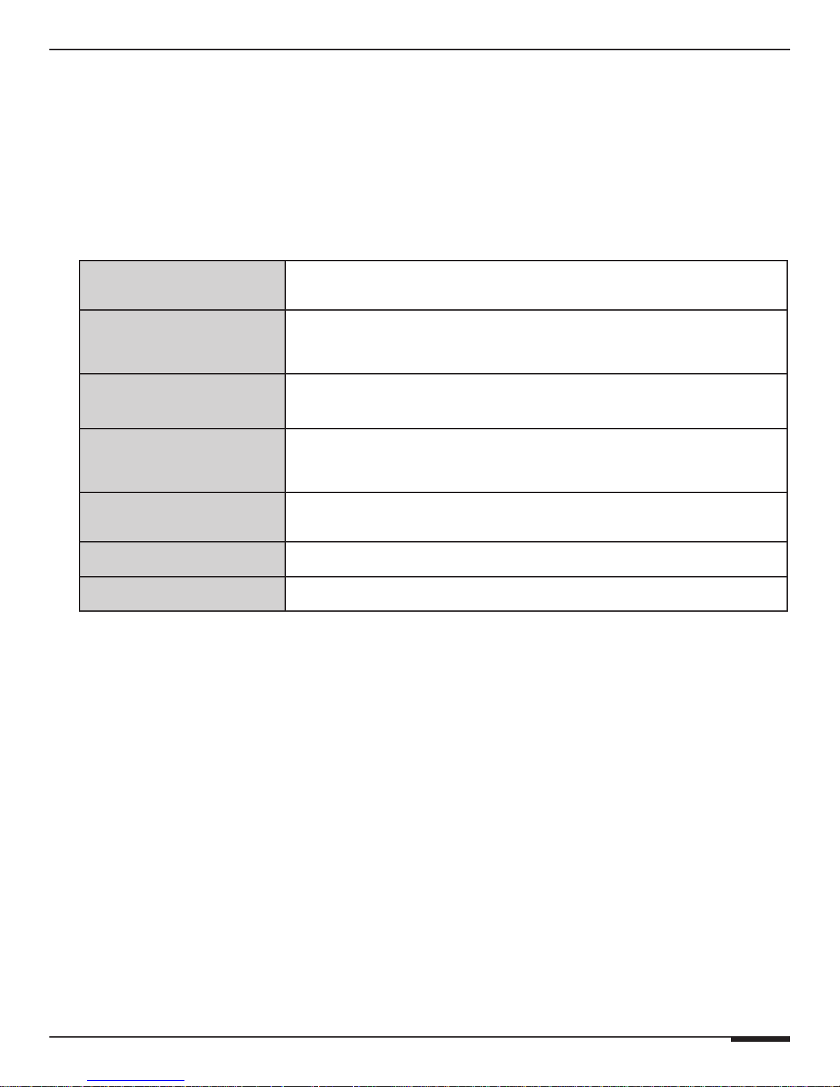
This manual provides step-by-step installation instructions and connection examples, along with basic user
information for installation and ongoing use of the A6 Six Channel Amplifier. This manual is written for the
installer of this equipment.
Organization
The following information is contained in this manual:
Safety Information
A6 Introduction
A6 System Design
Overview
A6 Connections
Troubleshooting
Specifications
Rack Mounting
Provides a comprehensive list of safety practices and procedures allowing for
the safe installation and operation of ELAN Home Systems’ A6 Six Channel Amplifier.
Provides an introduction to the A6 Six Channel Amplifier, along with system features
to include Front and Rear panel controls, indicators and connections, along with a
short description of each.
Provides a system design application overview of the A6 Six Channel Amplifier for
use in audio applications.
Provides a description of A6 Six Channel Amplifier connections including
connections made with ELAN Multi-Room Systems and direct connections to
the A6 Six Channel Amplifier from other components.
Provides troubleshooting tables to help fix common discrepancies that may
be associated with the A6 Six Channel Amplifier.
Appendix A provides equipment specifications for the A6 Six Channel Amplifier.
Appendix B provides specifications for Rack Mounting of the A6 Six Channel
Amplifier using the included rack mount brackets.
© ELAN Home Systems 2009 • All rights reserved. Page I
Page 4
A6 INSTALLATION MANUAL
CAUTION: TO REDUCE THE RISK OF ELECTRIC SHOCK, DO NOT
REMOVE COVER (OR BACK). NO USER SERVICEABLE PARTS INSIDE.
REFER SERVICING TO QUALIFIED SERVICE PERSONNEL.
CAUTION: RISK OF EXPLOSION IF BATTERY IS REPLACED BY AN
INCORRECT TYPE. DISPOSE OF USED BATTERIES ACCORDING TO
THE INSTRUCTIONS.
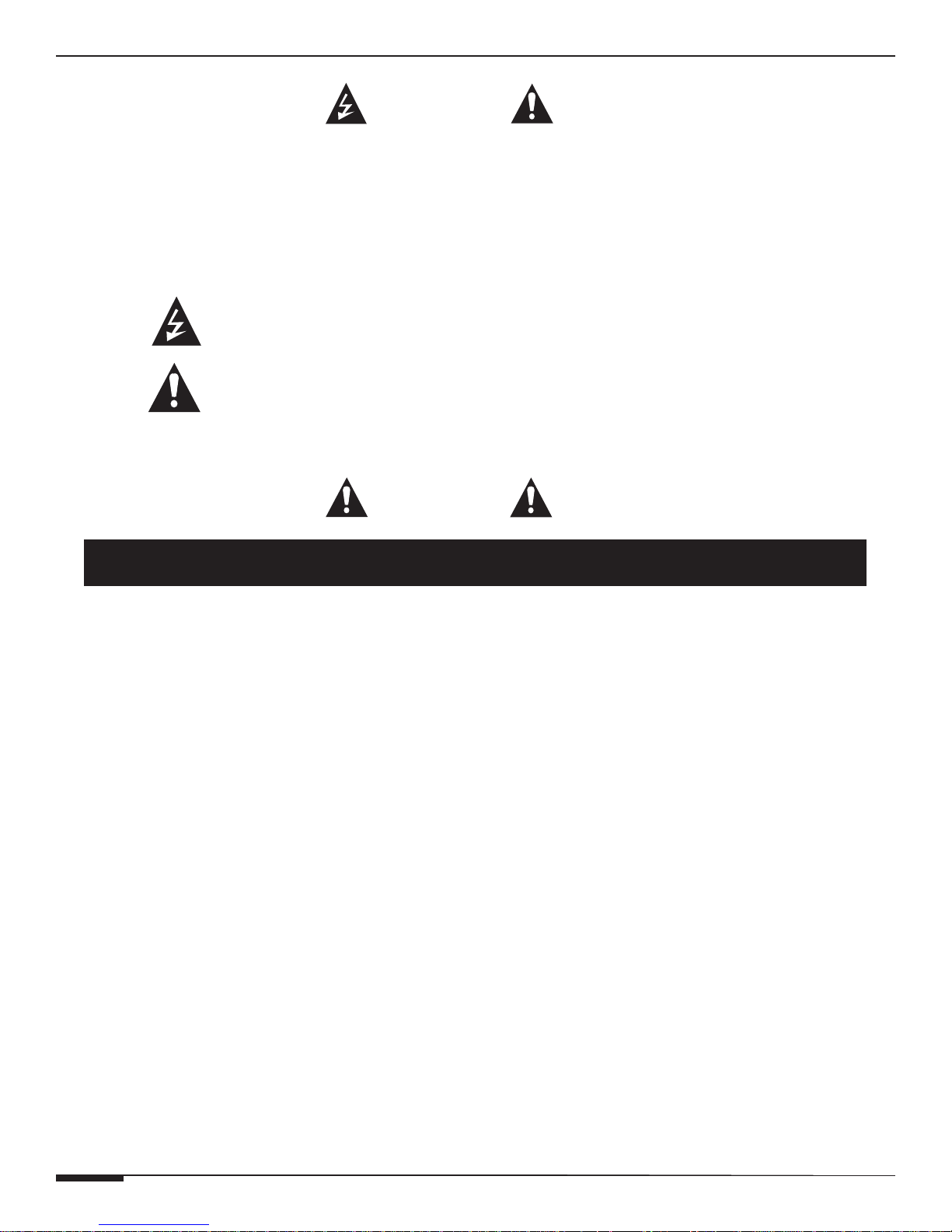
The lightning flash with arrowhead symbol within an equilateral triangle is intended to
alert the user to the presence of uninsulated "dangerous voltage" within the product's
enclosure that may be of sufficient magnitude to constitute a risk of electric shock to persons.
The exclamation point within an equilateral triangle is intended to alert the user to the presence
of important operating and maintenance (servicing) instruction in the literature accompanying
the appliance.
WARNING: TO REDUCE THE RISK OF FIRE OR SHOCK,
DO NOT EXPOSE THIS APPLIANCE TO RAIN OR MOISTURE.
WARNING
RISK OF ELECTRIC SHOCK
DO NOT OPEN!
E L A N H O M E S Y S T E M S
CAUTION
IMPORTANT SAFETY INFORMATION
Read Information—All the safety and operating information should be read before the appliance is operated.
Follow Information—All operating and use information should be followed.
Retain Information—The safety and operating information should be retained for future reference.
Heed Warnings—All warnings on the appliance and in the operating instructions should be heeded.
Wall Mounting—Mounting of this appliance should be done only by an authorized installer.
Ventilation—The appliances should be situated so that their location or position does not interfere with their proper ventilation. These appli-
ances should never be placed near or over a radiator or heat register. These appliances should not be placed in a built-in installation such as a
bookcase or cabinet that may impede the flow of air through the ventilation openings.
Non-Use Periods—Appliances that are left unattended and unused for long periods of time should be de-energized.
Power Sources—The appliances should be connected to a power supply only of the type described in the operating instructions or as
marked on each appliance. If you are not sure of the type of power supply to your home, consult your authorized ELAN dealer or local power
company.
Grounding or Polarization—Do not defeat the safety purpose of the polarized or grounding-type plug. A polarized plug has two
blades with one blade wider than the other blade. A grounding type plug has two blades and a third grounding prong. The polarized wide blade
and the third prong are provided for your safety. If the provided plug does not fit your outlet, consult an electrician for replacement of the obsolete
outlet.
Water and Moisture—To reduce the risk of electric shock or fire, these appliances should not be used near water ––for example, near a
bathtub, washbowl, kitchen sink, laundry tub, in a wet basement, or near a swimming pool.
Power Cord Protection—Protect the power cord from being walked on or pinched particularly at plugs, convenience receptacles and
the point where they exit from the apparatus.
Telephones—Avoid using a telephone (other than a cordless type) during an electrical storm. There may be a remote risk of electrical shock
from lightning. Do not use a telephone to report a gas leak if the leak is in the vicinity of the ELAN electronic equipment because of risk of fire or
explosion.
Page II © ELAN Home Systems 2009 • All rights reserved.
Page 5
E L A N H O M E S Y S T E M S
A6 INSTALLATION MANUAL
Cleaning—Unplug the apparatus from the power outlet before cleaning. Use only a dry cloth to clean the apparatus.
Power Lines—An outdoor antenna should be located away from power lines. When installing an outside antenna system, extreme care
should be taken to avoid touching power lines or circuits, as contact with them may be fatal.
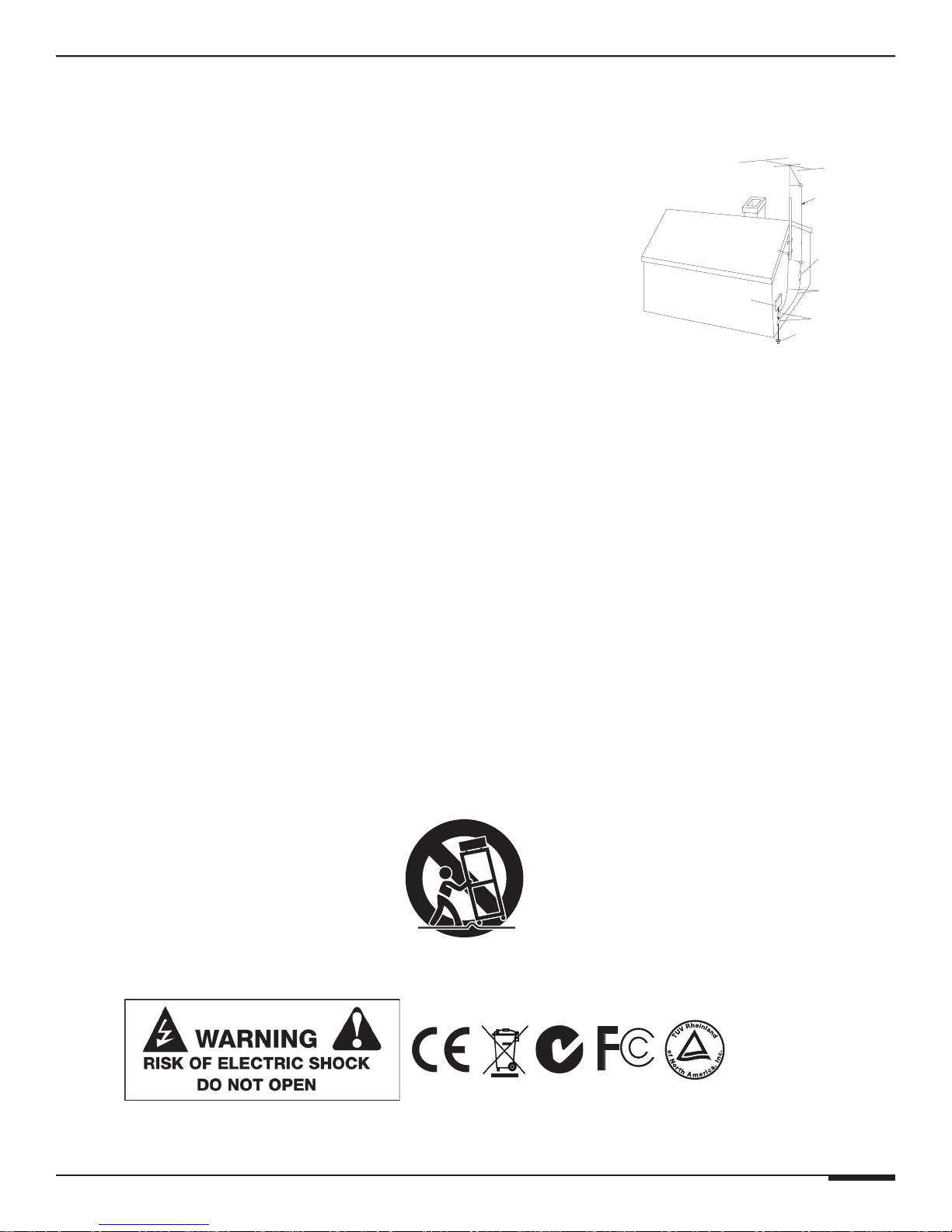
Outdoor Antenna Grounding—If an outside antenna or cable system
is connected to these audio products, be sure the antenna or cable system is grounded
so as to provide some protection against voltage surges and built-up static charges. Section 810 of the U.S. National Electrical Code, and Section 54 of the
Grounding
Diagram
ANTENNA
LEAD-IN WIRE
Canadian Electrical Code, provide information with respect to proper grounding of
the mast and supporting structure, grounding of the lead-in wire to an antenna
discharge unit, size of grounding conductors, location of antenna-discharge unit,
connection to grounding electrodes, and requirements for the grounding electrode.
See the grounding diagram (right).
Overloading—Do not overload wall outlets and extension cords, as this could
result in fire or electric shock.
Object and Liquid Entry—Never insert objects of any kind through the
NE C - NATIONAL ELECTRICAL CODE
CE C - CANADIAN ELECTRICAL CODE
ELECTRIC
SERVICE
EQUIPMENT
GROUND
CLAMPS
ANTENNA LEAD-IN WIRE
(CEC SECTION 54-200)
(NEC SECTION 810-20)
GROUNDING CONDUCTORS
(CEC SECTION 54-200)
(NEC SECTION 810-21)
GROUND CLAMPS
POWER SERVICE GROUNDING
ELECTRODE SYSTEM
(CEC SECTION 10-700)
(NEC AR TICLE 250, PART H)
openings of these appliances, as they may touch dangerous voltage points or
short-out parts that could result in a fire or electric shock. Care should be taken so that
objects do not fall and liquids are not spilled into the appliance through openings in the enclosure.
Servicing—Do not attempt to service these appliances yourself, as opening or removing covers may expose you to dangerous voltage or
other hazards. Refer all servicing to qualified service personnel.
Damage Requiring Service—These appliances should be serviced by qualified service personnel when:
• A power supply connection or a plug has been damaged or
• If liquid has been spilled into the appliance or objects have fallen into the appliance or
• The appliance has been exposed to water or moisture or
• The appliance does not appear to operate normally or exhibits a marked change in performance or
• The appliance has been dropped or the enclosure damaged.
Replacement Parts—When replacement parts are required, be sure the service technician has used replacement parts specified by
the manufacturer or that have the same characteristics as the original part. Unauthorized substitutions may result in fire, electric shock, or other
hazards. The Master Control Unit battery should be replaced only after turning the power off and only by an authorized installer.
Safety Check—Upon completion of any service or repairs to this audio product, ask the service technician to perform safety checks to
determine that the audio product is in proper operating condition.
Lightning Storms—Unplug this apparatus during lightning storms or when unused for long periods of time.
Attachments and Accessories—Use only attachments/accessories specified by the manufacturer.
Cart, Stand, Tripod, Bracket or Table—Use only with a cart, stand, tripod, bracket or table specified by the manufacturer, or
sold with the apparatus. When a cart is used, use caution when moving the cart/apparatus combination to avoid injury from tip over.
Disconnect Device—Where the mains plug or an appliance coupler is used as the disconnect device, the disconnect device shall remain
operable.
®
C
US
© ELAN Home Systems 2009 • All rights reserved. Page III
Page 6

A6 INSTALLATION MANUAL
E L A N H O M E S Y S T E M S
Page IV © ELAN Home Systems 2009 • All rights reserved.
Page 7

E L A N H O M E S Y S T E M S
A6 INSTALLATION MANUAL
Table of Contents
Purpose of This Manual ....................................................................................................................... I
Organization ........................................................................................................................................... I
Safety Information ............................................................................................................................... II
Chapter 1:
Introduction
Introduction ........................................................................................................................................... 1
A6 Features ........................................................................................................................................... 1
A6 Functions & Indicators .................................................................................................................. 2
Front Panel .......................................................................................................................................... 2
Rear Panel ........................................................................................................................................... 3
Chapter 2:
A6 System Design Overview
System Design ...................................................................................................................................... 4
Pre-Wire .............................................................................................................................................. 4
Applications .......................................................................................................................................... 5
Multi-Room Applications ..................................................................................................................... 5
Stereo Zones ...................................................................................................................................... 5
Stereo Zone w/ Mono Sub-Zone ............................................................................................................ 9
S66A/S86A Application ....................................................................................................................... 10
S86A Application ............................................................................................................................... 11
Bridge Application ............................................................................................................................. 12
Chapter 3:
A6 Connections
Connections ........................................................................................................................................ 13
Line Inputs ........................................................................................................................................ 13
Line Outputs ...................................................................................................................................... 14
Speaker Connections .................................................................................................................... 15
Triggers .............................................................................................................................................. 16
System Trigger In ............................................................................................................................... 16
System Trigger Out ............................................................................................................................ 16
IR Connections ................................................................................................................................ 17
IR In ................................................................................................................................................... 17
IR Out ............................................................................................................................................... 17
IR System Control ............................................................................................................................. 18
Chapter 4:
Chapter 5: Troubleshooting .............................................................................................................. 21
Appendix A: Specifications ................................................................................................................. 24
Appendix B: Rack Mounting .............................................................................................................. 25
Warranty ................................................................................................................................ Back Page
Operations and Settings ............................................................................................... 19
© ELAN Home Systems 2009 • All rights reserved. Page V
Page 8
A6 INSTALLATION MANUAL
E L A N H O M E S Y S T E M S
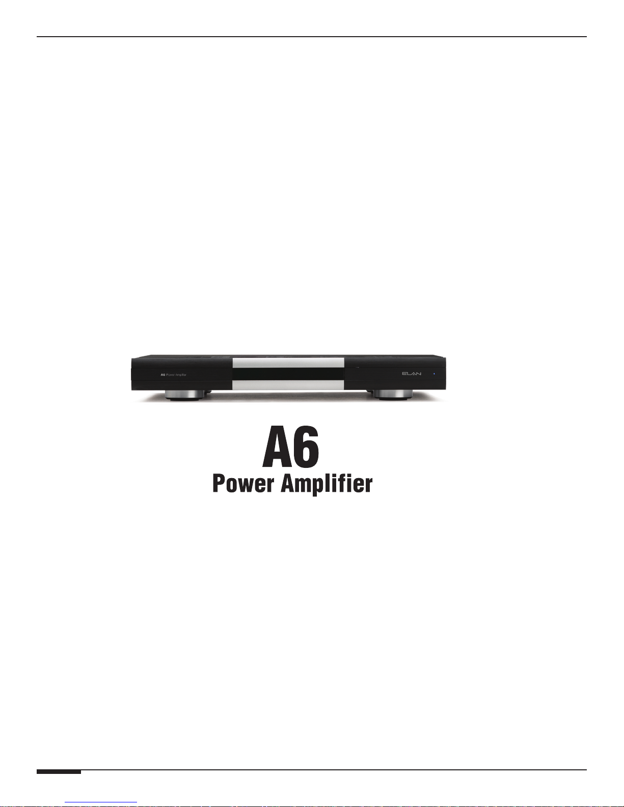
Items in package:
• A6PowerAmplifier
• RackMountBrackets
• PowerCord
• InstallationManual
Page VI © ELAN Home Systems 2009 • All rights reserved.
Page 9
E L A N H O M E S Y S T E M S
A6 INSTALLATION MANUAL
Chapter 1: Introduction
The ELAN A6 Power Amplifier is designed to provide a reliable, affordable solution for multi-room audio systems
requiring up to six channels of amplification. Using proven analog technology, the A6 adds advanced features like
Audio Sensing, Stereo/Mono Bus, and Trigger Inputs/Outputs to make it the premier amplifier in its price range.
A6 Features
6 x 60 Watts per Channel @ 8 Ohms
3 x 120 Watts per Channel @ 8 Ohms
• An output pair can be combined using a simple switch to send 120 WPC
of BRIDGED MODE audio to a passive sub-woofer.
• BUS MODE switching allows the bussed signal to be
sent to all channel outputs, excellent for commercial applications.
System Trigger In/Out
• SYSTEM TRIGGER IN allows all channels of the
amplifier to turn on when a signal is received.
• SYSTEM TRIGGER OUT sends a +12VDC pulse
whenever any of the channels of the amplifier are on.
Audio Line Outputs
• Send audio signals out from specific A6 channels
to line level inputs of other devices such as additional A6
amplifiers or audio processors.
Individual Channel Level Adjustments
• Fine-tune each channel’s level using precision potentiometers.
5-Way Speaker Binding Post
• The A6 is equipped with gold plated, 5-way speaker binding post.
This allows for five methods of speaker wire termination: bare wire,
spade lug, pin, single banana and dual banana plug.
IR Port Input
• +12VDC, GND, and IR Input plug allows up to four IR Receivers to pass-through
IR signals through the IR OUTPUT port adding more options and flexibility
to any IR signal routing
Safety Concerns
Use only grounded outlets when powering this product. Making any modification to the power cord could cause
unsafe operation and will void the manufacturer’s warranty.
AC Power Considerations
The A6 requires 3.7 Amps of AC current. When designing any whole house system using multichannel amplifiers,
make sure to provide adequate provisions for all electronic equipment to be installed. This may require additional
outlets and/or circuit breakers tobe installed. Consult a licensed electrician in this case.
ALL CONNECTIONS SHOULD BE MADE
WITH THE AMPLIFIER TURNED OFF
AND UNPLUGGED FROM POWER.
DAMAGE CAN OCCUR TO EQUIPMENT
IF IMPROPER CONNECTIONS ARE MADE!
© ELAN Home Systems 2009 • All rights reserved. Page 1
THIS AMPLIFIER IS BRIDGEABLE!
DO NOT TRY TO BRIDGE OUTPUTS
WHILE AMPLIFIER IS ON!
DAMAGE TO THE AMP CAN OCCUR.
Page 10
A6 INSTALLATION MANUAL
A6 Functions and Indicators
FRONT
E L A N H O M E S Y S T E M S
3
}
}
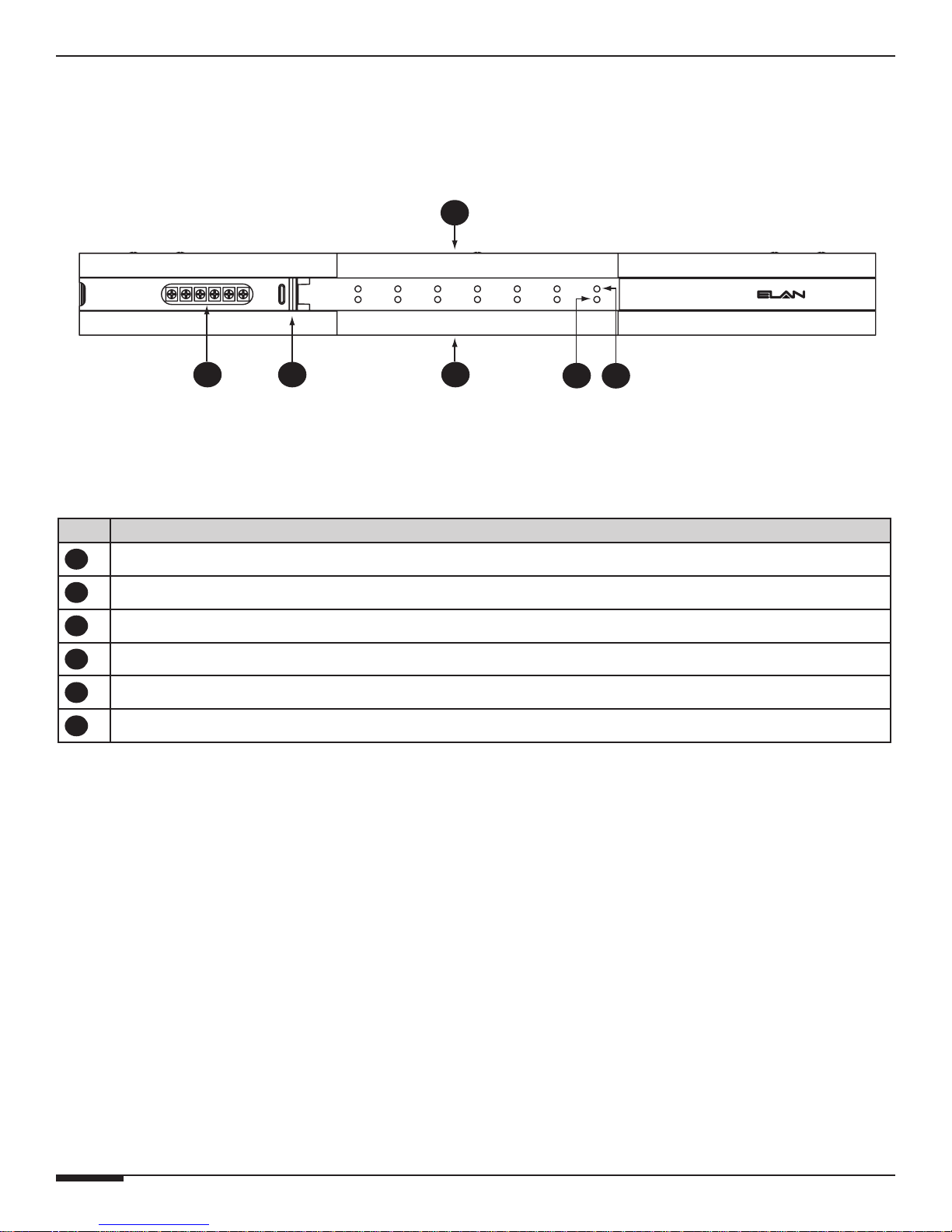
Item Function
Channel Gain Potentiometers (6)
1
Pull-Out Access Door
2
Channel ON/OFF LED Indicators - Glows Blue When Channel is ON
3
Channel Clipping LED Indicators - Glows Red When Channel is Clipping
4
Power LED - Glows Blue When Power Switch is ON and Unit Plugged In
5
IR LED - Glows Green When IR is Received
6
1 2 4
Figure 1-1: A6 Front Panel
Table 1-1:Front Panel
5
6
Page 2 © ELAN Home Systems 2009 • All rights reserved.
Page 11
E L A N H O M E S Y S T E M S
A6 Rear
A6 INSTALLATION MANUAL
BACK
1
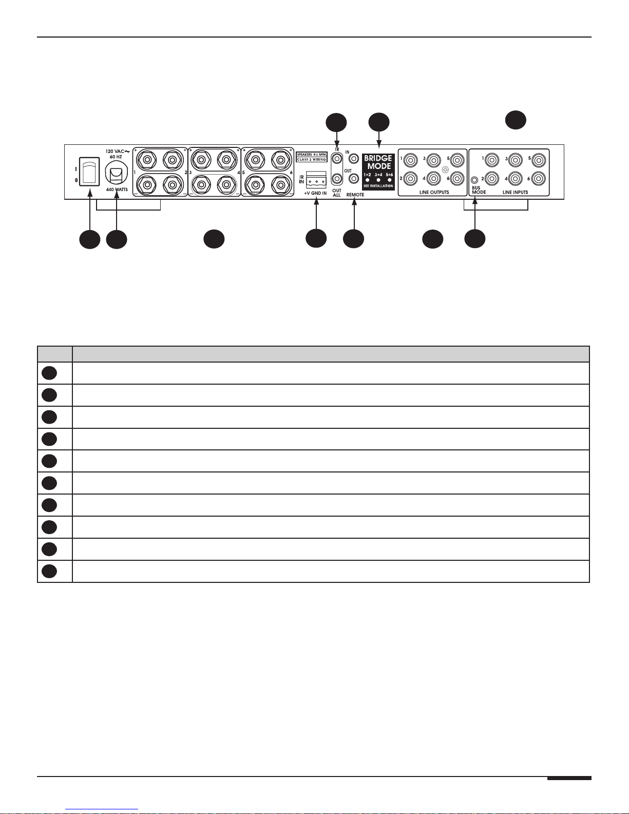
Item Function
Power Switch
1
Power Cord
2
Speaker OUTPUTS
3
10
9
8
}
}
2
3
Figure 1-2: A6 Rear Panel
Table 1-2: Rear Panel
4
5
}
6
7
10
IR Receiver Port
4
System Trigger IN/OUT
5
RCA LINE OUTPUTS
6
BUS MODE Button
7
RCA LINE INPUTS
8
BRIDGE MODE Buttons
9
IR IN/OUT
© ELAN Home Systems 2009 • All rights reserved. Page 3
Page 12
A6 INSTALLATION MANUAL
E L A N H O M E S Y S T E M S
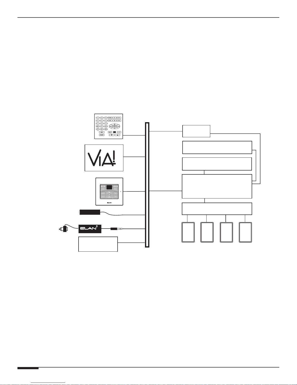
Chapter 2. System Design & Applications
System Design
The first step to a good design is to map the system. It is advisable to mark up a copy of the house floor plan with
speaker, keypad, touch panel, volume control, and equipment locations etc. Make sure that all locations are decided
upon before pre-wiring commences so that all necessary wiring and installation hardware is in place. This unit will
be interfacing with other components such as multi-room controllers, source components, communications controllers, serial controllers, and user interfaces, so it is essential that ALL system components are accounted for prior to
the pre-wire stage.
Secondly, make a detailed list of all components. Include source equipment, keypads, touch panels, volume controls, amplifiers, and communications gear. Be sure to include necessary electrical boxes, structured wiring enclosures, telephone lines, rough-in brackets, patch cords, power supplies, etc.
External IR
Receivers
Sensors
Keypads
Olé
Touchpads
AUDIO SENSOR
Triggered
Devices
FrontRear
SS1
TM
A/V Sources
C2
S66A
A6 Amplifier
SPK SPK SPK SPK
SPP
(side view)
Pre-Wire
Wiring Considerations
• Speaker Wires 28-16 AWG Speaker Wire
• Audio Cables RCA Patch Cables
• Triggers 2 Conductor Wire w/ 3.5mm mono connector
Page 4 © ELAN Home Systems 2009 • All rights reserved.
Figure 2-1: System Design
Page 13
E L A N H O M E S Y S T E M S
A6 INSTALLATION MANUAL
Applications
The A6 is designed for single or multi-room applications. Every feature was selected to enhance both the single or
multi-room experience and simplify any installation. With Buffered Line Outputs, Bus Mode, and Remote Trigger
options, the A6 can be customized for even the most complex systems.
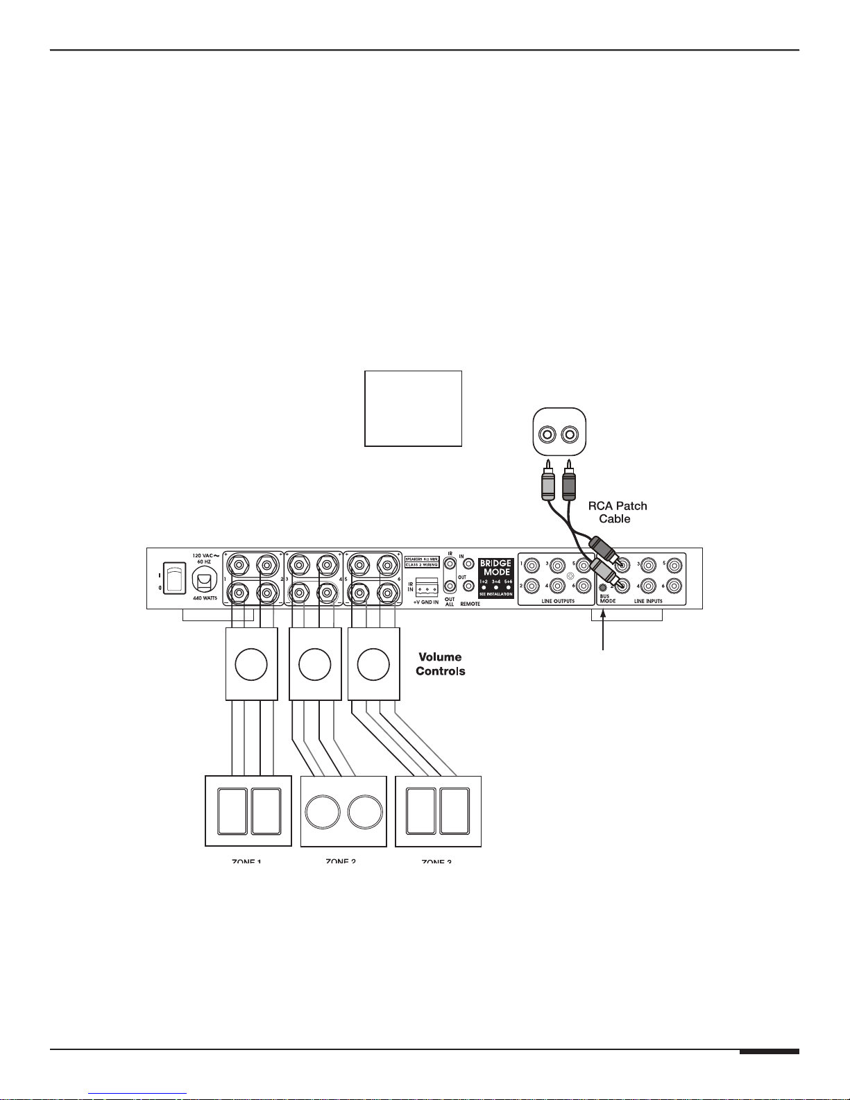
Three Stereo Listening Areas
By utilizing the Bus Mode button on the A6, multiple rooms in the home can share a single source such as a
Receiver or CD player. As shown below, each speaker pair of will ramp volume up and down independently.
Three Stereo Zones
• Stereo Output to Line Inputs 1 & 2
• Bus Mode Button switched to ON
• Volume Controls on Each Speaker Output
Each Area Has Independent Volume Control
Line Level
Set A6
BUS MODE
Button
To ON
Analog Audio
Output
RL
A6
Bus Mode Button
Figure 2-2: Independent Stereo Zones
© ELAN Home Systems 2009 • All rights reserved. Page 5
Page 14
A6 INSTALLATION MANUAL
E L A N H O M E S Y S T E M S
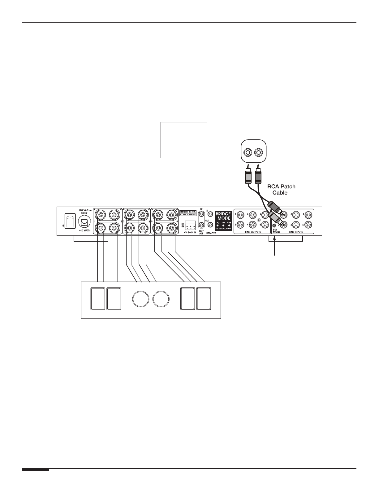
Wide Coverage
The A6 is designed to easily handle a Great Room application without any special setup procedures. In the example
below, each speaker pair of will ramp volume up and down simultaneously.
Wide Coverage Stereo Zones
• Stereo Output to Line Inputs 1 & 2
• Bus Mode Button switched to ON
•
All Speakers Volume Ramps Up & Down Simultaneously
Line Level
Set A6
BUS MODE
Button
To ON
Analog Audio
Output
RL
A6
Bus Mode Button
Wide Coverage Zone
Figure 2-3: Wide Coverage Stereo Zones
Page 6 © ELAN Home Systems 2009 • All rights reserved.
Page 15
E L A N H O M E S Y S T E M S
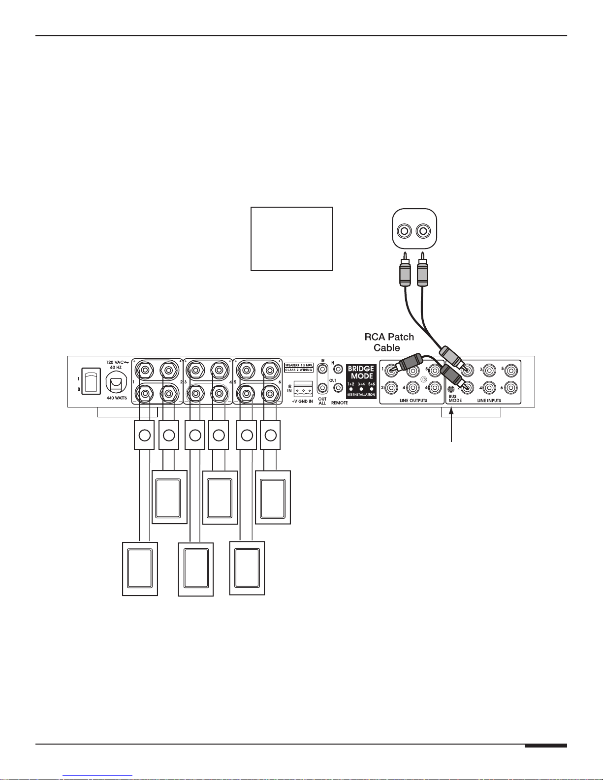
This amplifier is great for commercial applications such as restaurants and sports bars. In the example below, each
speaker will ramp volume up and down independently.
A6 INSTALLATION MANUAL
Wide Coverage Mono Zones
• Stereo Output to RCA ‘Y’ Cable to Line Input 1
• Line Output 1 to Line Input 2
• Bus Mode Button switched to ON
• Mono Volume Controls on Each Speaker Output
All Speakers Volume Ramps Up & Down Independently
A6
Set A6
BUS MODE
Button
To ON
Line Level
Analog Audio
RL
Output
RCA ‘Y’
Patch Cable
Bus Mode Button
© ELAN Home Systems 2009 • All rights reserved. Page 7
Wide Coverage
Mono Zones
Figure 2-4: Wide Coverage Mono Zones
Page 16
A6 INSTALLATION MANUAL
E L A N H O M E S Y S T E M S
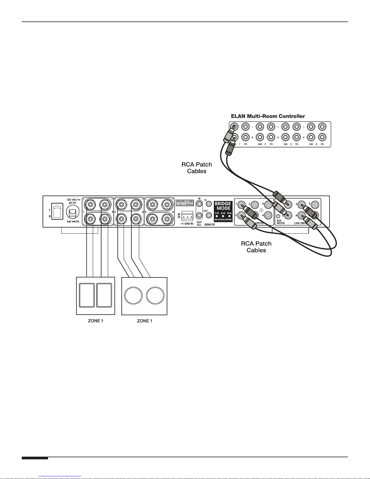
Two Room Stereo Zone
By using the A6’s Buffered Line Outputs, an additional pair of speakers can be added to a zone. In this example,
both pairs of speakers will ramp volume up and down simultaneously.
Two Room Stereo Zone
• Zone 1 Output to Line Inputs 1 & 2
• Line Outputs 1 & 2 to Line Inputs 3 & 4
All Speakers Volume Ramps Up & Down Together
ZONE OUTPUTS
A6
Page 8 © ELAN Home Systems 2009 • All rights reserved.
Figure 2-5: Two Room Stereo Zone
Page 17
E L A N H O M E S Y S T E M S
A6 INSTALLATION MANUAL
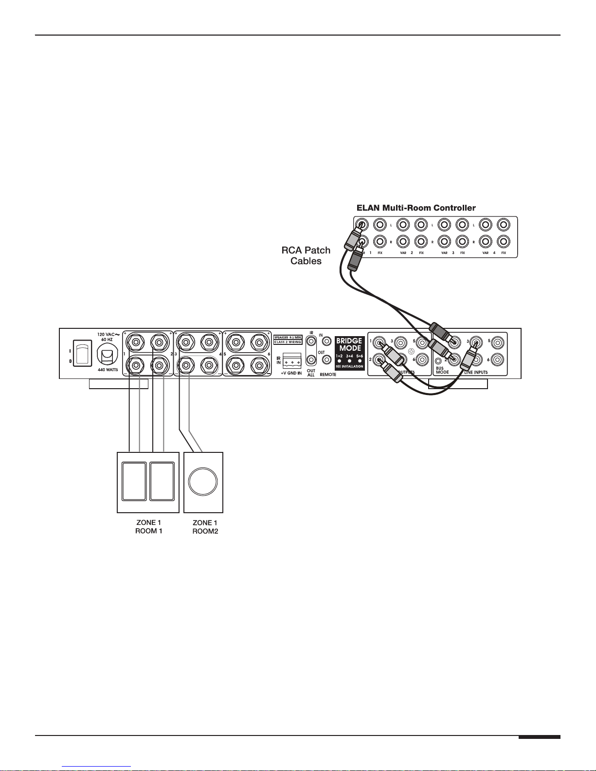
Stereo Zone w/ Mono Sub-Zone
Use the Line Output Jacks and an RCA ‘Y’ cable to create mono sub-zones within a stereo zone. This application
is perfect for large rooms with smaller rooms attached such as a Master Bedroom/Master Bath or Kitchen/Laundry
Room.
Stereo Zone w/ Mono Sub-Zone
• Zone 1 Output to Line Inputs 1 & 2
• Line Outputs 1 & 2 to RCA ‘Y’ Cable
• RCA ‘Y’ Cable to Line Input 3
All Speakers Volume Ramps Up & Down Together
ZONE OUTPUTS
Figure 2-6: Stereo Zone with Mono Sub-Zone
RCA ‘Y’
Cable
© ELAN Home Systems 2009 • All rights reserved. Page 9
Page 18
A6 INSTALLATION MANUAL
E L A N H O M E S Y S T E M S
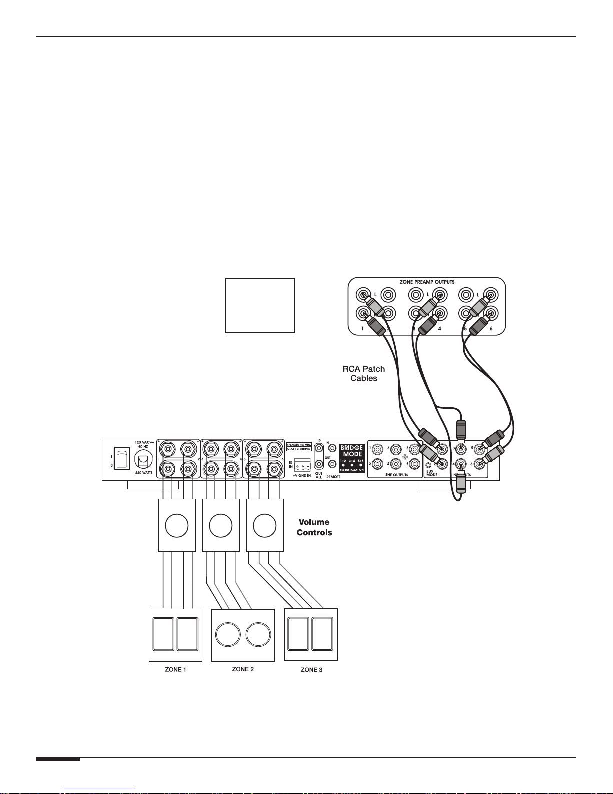
S66A/ S86A Sub-Zones
ELAN’s S66A/S86A Integrated Multi-Room Controllers have built-in amplification for six stereo zones as well as six
sets of preamp outputs for the addition of sub-zones. The A6 is ideally suited to amplify these subzones using rotary
or electronic volume controls if separate volume up/down functionality is desired in the sub-zones as shown in the
S66A example below
S66A Sub-Zones
• Preamp Output 1 & 2 to Line Inputs 1 & 2
• Preamp Output 3 & 4 to Line Inputs 3 & 4
• Preamp Output 5 & 6 to Line Inputs 5 & 6
• Preamp Output DIP Switches Set to Fixed
• Volume Controls on Each Speaker Output
Each Zone and Sub-Zone Has Independent Volume Control
S66A
Set S66A
ZONE PREAMP
OUTPUT MODE
DIP Switches
To Fixed
A6
Figure 2-7: S66A/S86A Sub-Zones
Page 10 © ELAN Home Systems 2009 • All rights reserved.
Page 19
E L A N H O M E S Y S T E M S
A6 INSTALLATION MANUAL
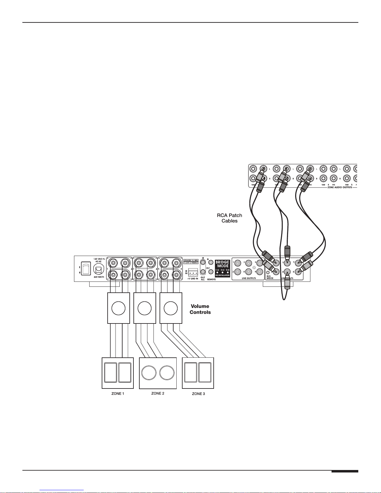
S128P Sub-Zones
ELAN’s S128P Integrated Multi-Room Controller has variable preamp outputs for eight stereo zones as well as eight
sets of fixed preamp outputs for the addition of sub-zones. The A6 is ideally suited to amplify these subzones using
rotary or electronic volume controls if separate volume up/down functionality is desired in the sub-zones.
S128P Sub-Zones
• Fixed Preamp Output 1 & 2 to Line Inputs 1 & 2
• Fixed Preamp Output 3 & 4 to Line Inputs 3 & 4
• Fixed Preamp Output 5 & 6 to Line Inputs 5 & 6
• Volume Controls on Each Speaker Output
Each Zone and Sub-Zone Has Independent Volume Control
S128P
A6
Figure 2-8: S128P Sub-Zones
© ELAN Home Systems 2009 • All rights reserved. Page 11
Page 20

A6 INSTALLATION MANUAL
E L A N H O M E S Y S T E M S
Bridged
ELAN’s A6 can also be "bridged" providing 3 channels at 120WPC for high power applications. The recessed
Channel Bridging buttons located on the back panel make custom configuration easy
NOTE: Make sure the A6 is OFF before engaging Channel Bridging buttons.
NOTE: DO NOT use Volume Controls when in Bridged Mode.
NOTE: Make sure to maintain a minimum 8 Ohm load.
Bridged Stereo Zone
• Stereo Output to Line Inputs 1 & 3
• Line Outputs 1 & 2 to RCA ‘Y’ Cable to Line Input 5
• Bridge Buttons 1-2, 3-4, 5-6 Engaged
All Speakers Volume Ramps Up & Down Together
A6
Passive
Sub-Woofer
Bridge Mode
Buttons
RL
RCA ‘Y’
Patch Cable
Line Level
Analog Audio
Output
Left
Speaker
Page 12 © ELAN Home Systems 2009 • All rights reserved.
Right
Speaker
Figure 2-9: 3 Channel Bridged
Page 21
E L A N H O M E S Y S T E M S
A6 INSTALLATION MANUAL
Chapter 3: Connections
The A6 has many rear panel connections so it is important to label them all correctly. Label all input/output cable
and speaker wires with their destination or source and this will save time during installation and any future upgrades
to the system.
Use high quality line level RCA connector type cables for source connections to ensure the lowest possible noise
and best sound performance. For most applications use 16AWG 2 conductor speaker cable. For wiring runs longer
than 80 ft. it is recommended to use 14AWG 2 conductor speaker cable. The A6's high quality, gold plated 5-way
binding post will accomodate speaker cabling sizes up to 12AWG. Attaching banana plugs will enable the connection of larger cable sizes. A 3.5mm mono interconnect cable may be used for amplifier and systems triggering.
Line Level Audio Inputs
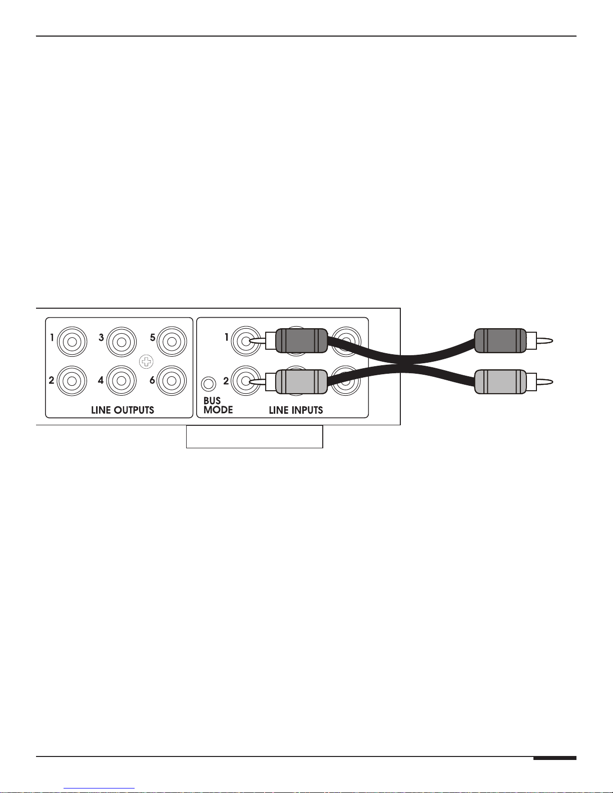
Connect the zones by inserting the RCA connectors into the dedicated direct input jack on each channel.
A6
From Audio
Output Source
RCA Patch
Cable
Figure 3-1: Line Inputs
© ELAN Home Systems 2009 • All rights reserved. Page 13
Page 22
A6 INSTALLATION MANUAL
E L A N H O M E S Y S T E M S
Signal Routing
The term BUS is dened as the ability to route a signal from one place to another. Traditional busing is done using
audio patch cables to route these signals. The use of Bus Mode Switch, such as the one on the A6, eliminates the
need for additional patch cables and adds to the exibility of signal routing when all Outputs share the same Input.
Line Ouputs
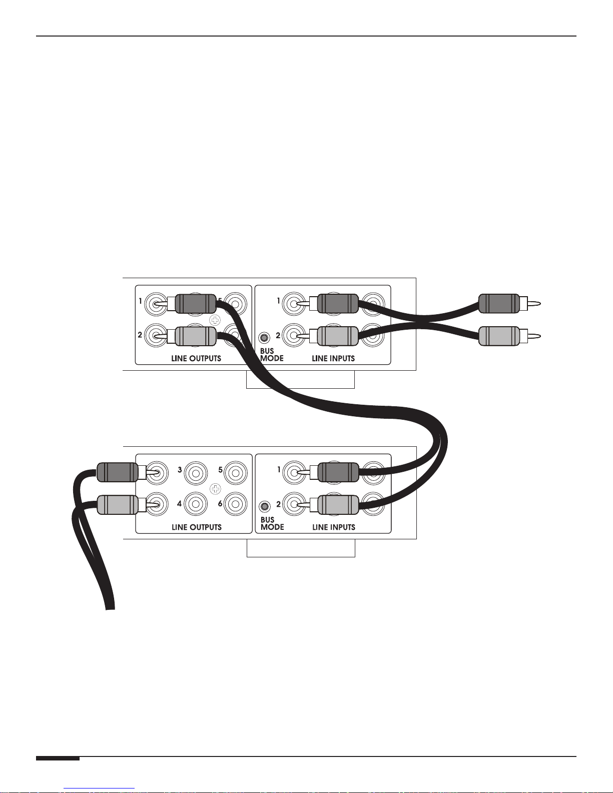
A stereo or monaural audio signal connected to the A6’s main CHANNEL INPUT can be routed to any of the A6’s six
channels via the RCA Line Outputs. This feature is excellent for standalone distributed audio systems where one
source (i.e. an A/V Receiver) is providing audio to the entire home, and also for ELAN multi-room applications where a
zone’s audio signal needs to be routed to multiple amplier channels. Examples of both these applications are shown
in the Chapter 2.
Line audio outputs enable connection of additional amplifiers to allow further system expansion. Use high quality
RCA interconnect cables to ensure low noise and great sound. The A6 Line Outputs are buffered, a maximum of four
amplifiers may be 'daisy-chained' to each Line Outputs.
A6 #1
A6 #2
From Audio
Output Source
RCA Patch
Cable
RCA Patch
Cable
RCA Patch
Cable
To A6
#3-4 etc.
Page 14 © ELAN Home Systems 2009 • All rights reserved.
Figure 3-2: Line Outputs
Page 23
E L A N H O M E S Y S T E M S
A6 INSTALLATION MANUAL
Speaker Binding Post
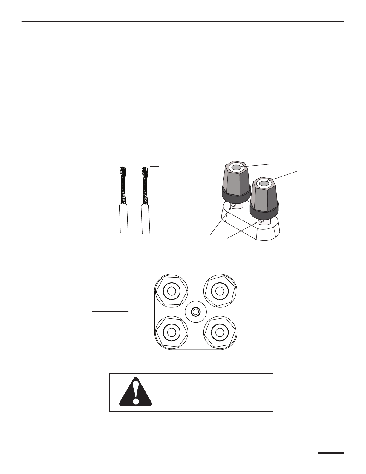
The A6 is equipped with gold plated, 5-way speaker binding post. This allows for five methods of speaker wire termination: bare wire, spade lug, pin, single banana and dual banana plug. Label all speaker wires with their destination to ensure easy configuration. To attach speaker wires use the following method:
1. Carefully split the speaker wire insulation at least two inches.
2. Strip 1/2 inch of the insulation from the speaker wire conductor exposing the bare wire.
3.Twist the wire strands of each conductor, if using banana plugs, attach wire to banana plug observing polarity.
4. If using banana plug; insert plug ends into binding post observing correct polarity. If using the bare wire method;
loosen red and black binding post caps and insert the bare wire through the hole in the post. Tighten the knob
until the wire is securely clamped.
CAUTION! Speaker Wire connections must be made with the amplifier OFF!
Banana Plugs
1/2’
Speaker Wire
A6 Amplifier
Binding Post
Speaker Wire
+
1
_
WARNING: Do not allow any strands
of the bare speaker wire to touch
the Amplifier Chassis or another
Connector.
+
2
_
© ELAN Home Systems 2009 • All rights reserved. Page 15
Figure 3-3: Speaker Binding Post
Page 24
A6 INSTALLATION MANUAL
E L A N H O M E S Y S T E M S
Triggers
A REMOTE TRIGGER IN port allows all channels to turn on or mute simultaneously. The REMOTE TRIGGER
INPUT can receive 5-24 Volts AC or DC. The 12 Volt DC REMOTE TRIGGER OUT can be used to turn on other
equipment, additional A6s or other amplifiers, or to perform automated functions desired by the user. Use
3.5mm mono interconnect cables to make Trigger connections.
SYSTEM TRIGGER IN
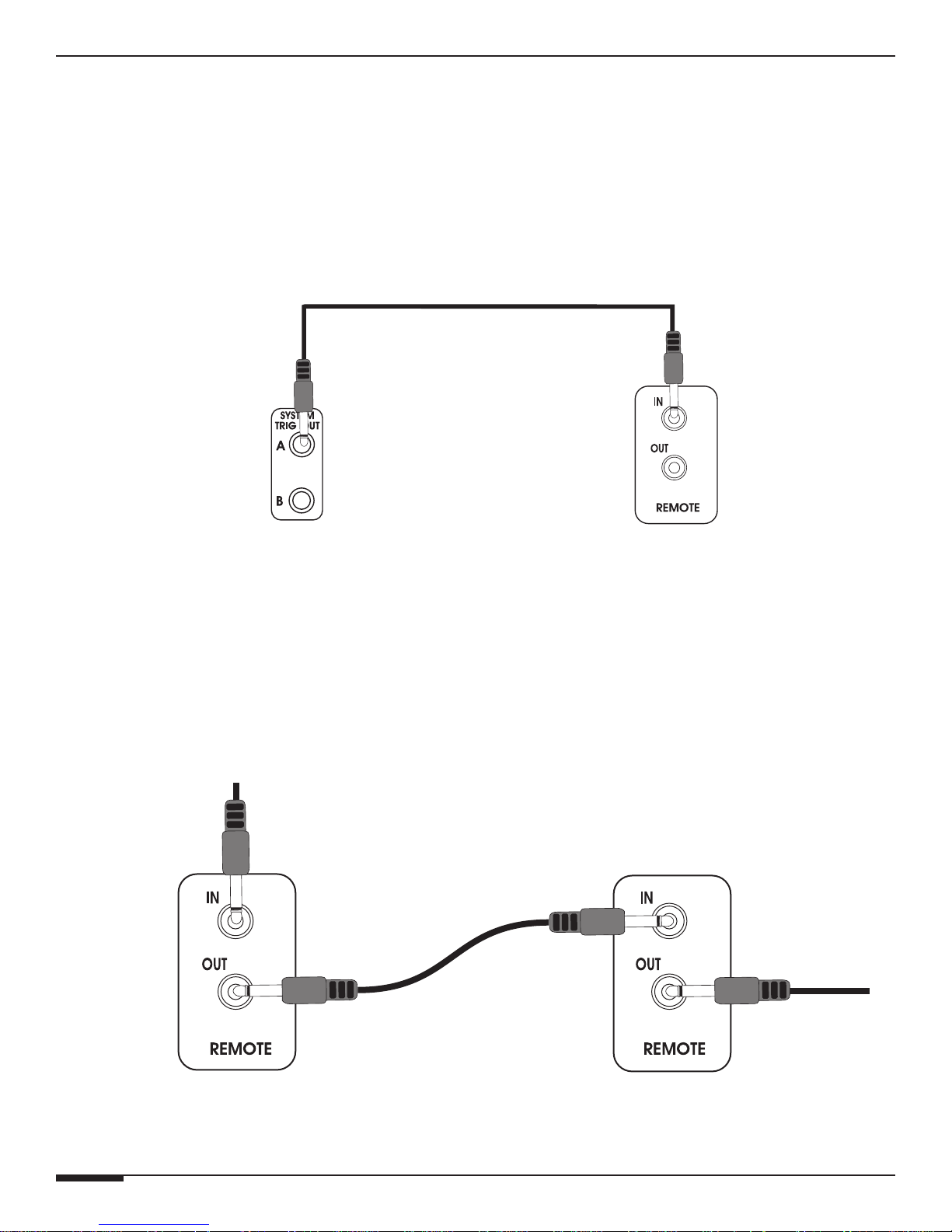
To mute/un-mute all channels simultaneously, connect a system-wide 5-24 Volt DC triggering source to the
SYSTEM TRIGGER IN port using a 3.5mm mono interconnect cable. Examples of triggering sources include an
ELAN Multi-Zone Controller’s SYSTEM TRIGGER OUT or REMOTE OUT, an A/V receiver’s switched outlet connected to a power supply, or a +12VDC TRIGGER OUT from another ELAN amplifier.
3.5mm mono
interconnect
cable
S66A
Figure 3-4: Remote Trigger In
SYSTEM TRIGGER OUT
Whenever the A6 is powered ON, the REMOTE TRIGGER OUT becomes active. This output sends a +12VDC
100mA signal to other devices with a Trigger Input. Examples of proper usage of the REMOTE TRIGGER OUT
include muting/un-muting other amplifiers, triggering the switched outlets of a Z•Power Controller, or triggering
automated events using ELAN®Sense Sensors and VIA! SR-1 or SS1 devices.
A6
From S66A
To A6
#3-4
A6 #1
Page 16 © ELAN Home Systems 2009 • All rights reserved.
3.5mm mono
interconnect
cable
A6 #2
Figure 3-5: Remote Trigger Out
Page 25
E L A N H O M E S Y S T E M S
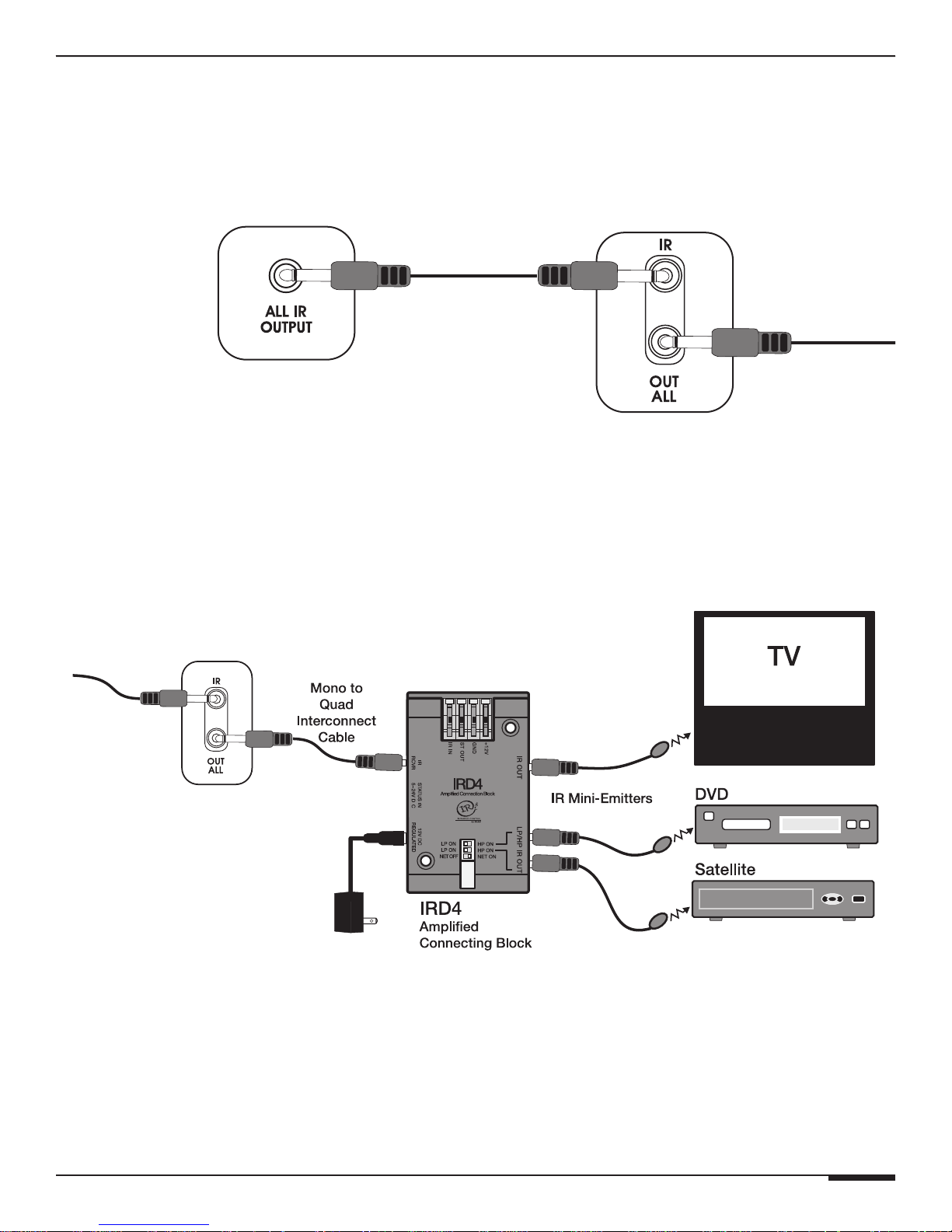
IR IN/OUT ALL Connections
The 3.5mm mono IR IN/OUT ALL is located beside the Remote Trigger jacks. This loop allows IR commands to be
sent through each A6 amplifier that is connected and out to additional IR devices such as the ELAN V8, or IRD4.
A6 INSTALLATION MANUAL
S66A A6
To ELAN
V8
Figure 3-6: IR IN Connection
From VSE2
A6
Figure 3-7: IR OUT ALL Connection
© ELAN Home Systems 2009 • All rights reserved. Page 17
Page 26
A6 INSTALLATION MANUAL
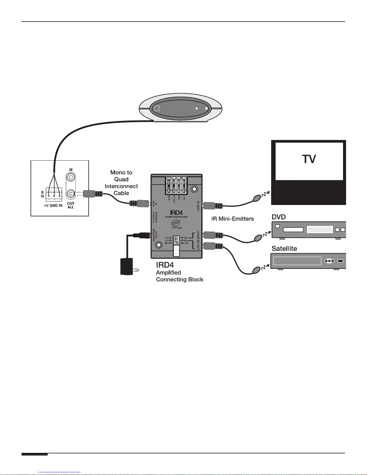
IR System Control Connections
An IR pass-through jack with removable IR wiring interface plug is located beside the IR IN/OUT ALL jacks. This
loop allows IR commands to be sent out the IR ALL OUT port to additional IR devices. The plug has connectors for
+12V, GND, IR IN that can accommodate and power up to 4 IR Receivers
E L A N H O M E S Y S T E M S
IRS5
A6
Figure 3-8: IR System Control Connection
Page 18 © ELAN Home Systems 2009 • All rights reserved.
Page 27
E L A N H O M E S Y S T E M S
A6 INSTALLATION MANUAL
Chapter 4: Operations & Settings
Setting Channel Levels
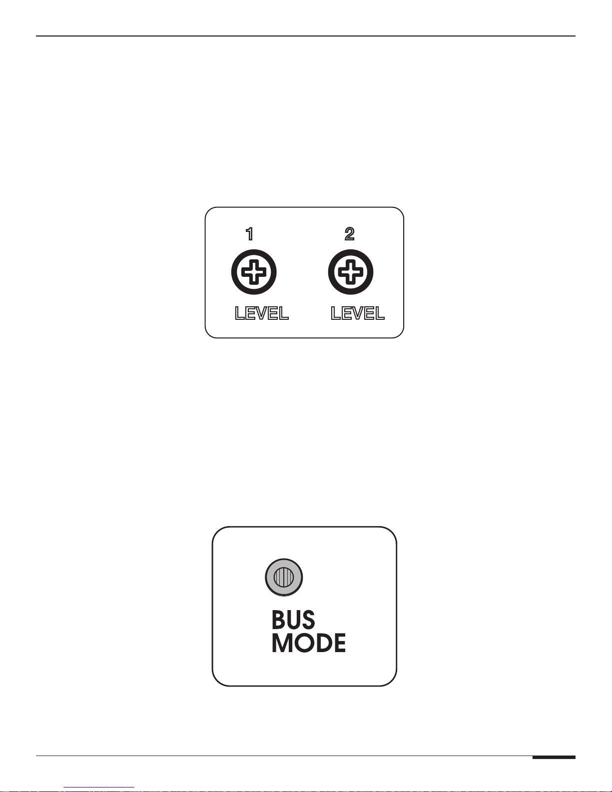
The A6 features independent Level Adjustment Potentiometers for each of its six channels. Use a small Phillips
screwdriver to independently adjust each channel of the amplifier for the specific speakers and environmental conditions of the area it is powering. Turning the potentiometers clockwise increases the level, while turning it counterclockwise decreases the level. Factory default is 50%.
Set the levels by first lowering them all the way down, then raise the volume of any keypads or volume controls to
maximum. Slowly increase the level of the channel being adjusted by turning the potentiometer clockwise until the
channel begins to distort, then reduce the level slightly (turn counter-clockwise) until distortion is no longer present.
Follow this procedure for each channel.
1 2
LEVEL LEVEL
Factory
Default 50%
Figure 4-1: Level Adjustment Potentiometers
BUS MODE Setting
The BUS MODE switch for the A6 is located on the back panel with the Line Input jacks. Audio signals connected to
the # 1 & 2 channels of the A6's LINE INPUT will be routed to channels 3 & 4, and 5 & 6 internally completely eliminating the need for patch cables.
© ELAN Home Systems 2009 • All rights reserved. Page 19
Figure 4-2: A6 Bus Mode Button
Page 28
A6 INSTALLATION MANUAL
E L A N H O M E S Y S T E M S
CHANNEL BRIDGE MODE Setting
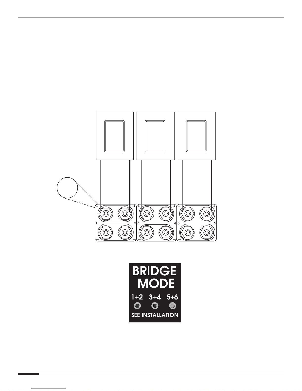
The Channel Bridging buttons for the A6 are located on the back panel next to the Line Outputs. These recessed
buttons are located beneath a decal. Using a small Phillips screwdriver carefully pierce the decal to access the button. The buttons are Factory Defaulted in the OUT (OFF) position. Audio signals connected to the # 1 & 3 & 5 channels of the A6's LINE INPUT will be routed to the top row of speaker outputs. See Figure 2-9: 3 Channel Bridged for
more details.
• Channel 1 & 2 Positive (+) Binding Post terminals become the bridged Output of Channel 1.
• Channel 3 & 4 Positive (+) Binding Post terminals become the bridged Output of Channel 3.
• Channel 5 & 6 Positive (+) Binding Post terminals become the bridged Output of Channel 5.
Speakers
8 Ohm
Minimum
+
Positive
Terminals
Speaker
Binding
Post
1 + 2 3 + 4 5 + 6
Bridge
Mode
Buttons
Figure 4-3: A6 Channel Bridge Mode Buttons
Page 20 © ELAN Home Systems 2009 • All rights reserved.
Page 29
E L A N H O M E S Y S T E M S
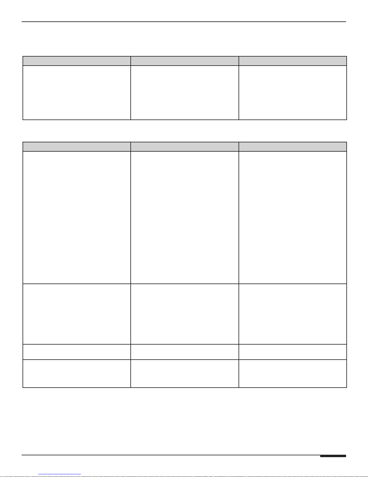
Chapter 5: Troubleshooting
Table 5-1: General
Symptom Possible Cause Solution
Amplifier Will Not
Power Up
1. Power switch is Off
1. Turn switch On. Switch is located on
the back of unit.
A6 INSTALLATION MANUAL
2. Circuit breaker tripped
2. Reset circuit breaker. The A6 draws
3.7A of AC currect. Ensure that
combined current draw of all devices
on circuit does not exceed the circuit’s
capacity.
Table 5-2: Audio
Symptom Possible Cause Solution
No Audio From One or
More Channels
1. Loose/bad speaker cable connection
2. Break/short in speaker cable
3. Speaker is defective
4. RCA patch cable defective
5. Source not sending audio
6. Bus Mode Button or Bridge Mode set
incorrectly. Verify BUS MODE or BRIDGE
MODE switch settings
1. Check cable ends at binding posts
and speaker terminals.
2. Check continuity of each speaker
cable using multimeter. If short or open
is indicated, check wiring for proper
connections.
3. Swap with known good speaker.
4. Swap with known good patch cable.
5. Verify source is powered up and playing. Check any tape monitor settings on
A/V Receiver.
6. Verify/correct switch settings.
No Audio From One Channel Amplifier is overheating due to
inadequate ventalation or prolonged
operation at clipping levels.
No Audio From One Channel Unit may require service. Contact ELAN Technical Support.
Very Low or No Sound on Some or All
Channels
© ELAN Home Systems 2009 • All rights reserved. Page 21
Audio input cable is bad. Check source equipment cables for
1. (a) Turn the amplifier off and allow the
internal circuits to cool.
(b) Ensure that the amplifier has
proper ventilation. Add cooling fan if
necessary.
(c) Lower the gain level controls for
that channel pair.
damage and faulty connections and correct.
Page 30

A6 INSTALLATION MANUAL
E L A N H O M E S Y S T E M S
Symptom Possible Cause Solution
Audio “Hum” 1. Ground potential difference between
source components (ground loop)
1. (a) Test AC outlet using ground tester.
(b) Reverse the AC plug of components with non-polarized ends plugged
into the same outlet strip as amp.
Distorted Audio at Normal
Volume Levels
2. Faulty/damaged cables
3. Faulty wiring
1. Input gain set too high
2. Defective/incompatible speaker
3. Volume control wired incorrectly
2. Check source equipment cables for
damage and faulty connections.
3. (a) Make sure volume controls are not
hooked up backwards.
(b) Check for shorts in wiring (see
item 2 in “No audio…”).
1. Reduce gain to the channel in question.
2. (a) Check for physical damage to
speaker.
(b) Ensure speakers have appropriate
power rating for amplifier.
(c) Ensure speakers are rated @ 8
Ohm impedance. This amp is compatible
with speakers with 8 Ohm impedance or
greater.
3. Check for proper input/output connections at volume control. Input comes
from amplifier, output goes to speakers.
Audio is Unclear, Bass
Response Low
Incorrect Source Playing
on Speakers
Amplifier Will Not
Power Up
4. Volume control Impedance Match
settings incorrect
Speakers out of phase Verify that + of amplifier goes to +of
1. Source connected to wrong
input of amplifier
2. Speakers connected to incorrect
speaker outputs
3. DIP switches set incorrectly
1. Power switch is Off
2. Circuit breaker tripped
4. Verify/correct Impedance Match settings.
speaker and - of amplifier goes to - of
speaker on ALL speaker leads.
1. Verify/correct input connections.
2. Verify/correct speaker connections.
3. Verify/correct DIP switch settings.
1. Turn switch On. Switch is located on
the back of unit.
2. Reset circuit breaker. Ensure that
combined current draw of all devices
on circuit does not exceed the circuit’s
capacity.
Page 22 © ELAN Home Systems 2009 • All rights reserved.
Page 31
E L A N H O M E S Y S T E M S
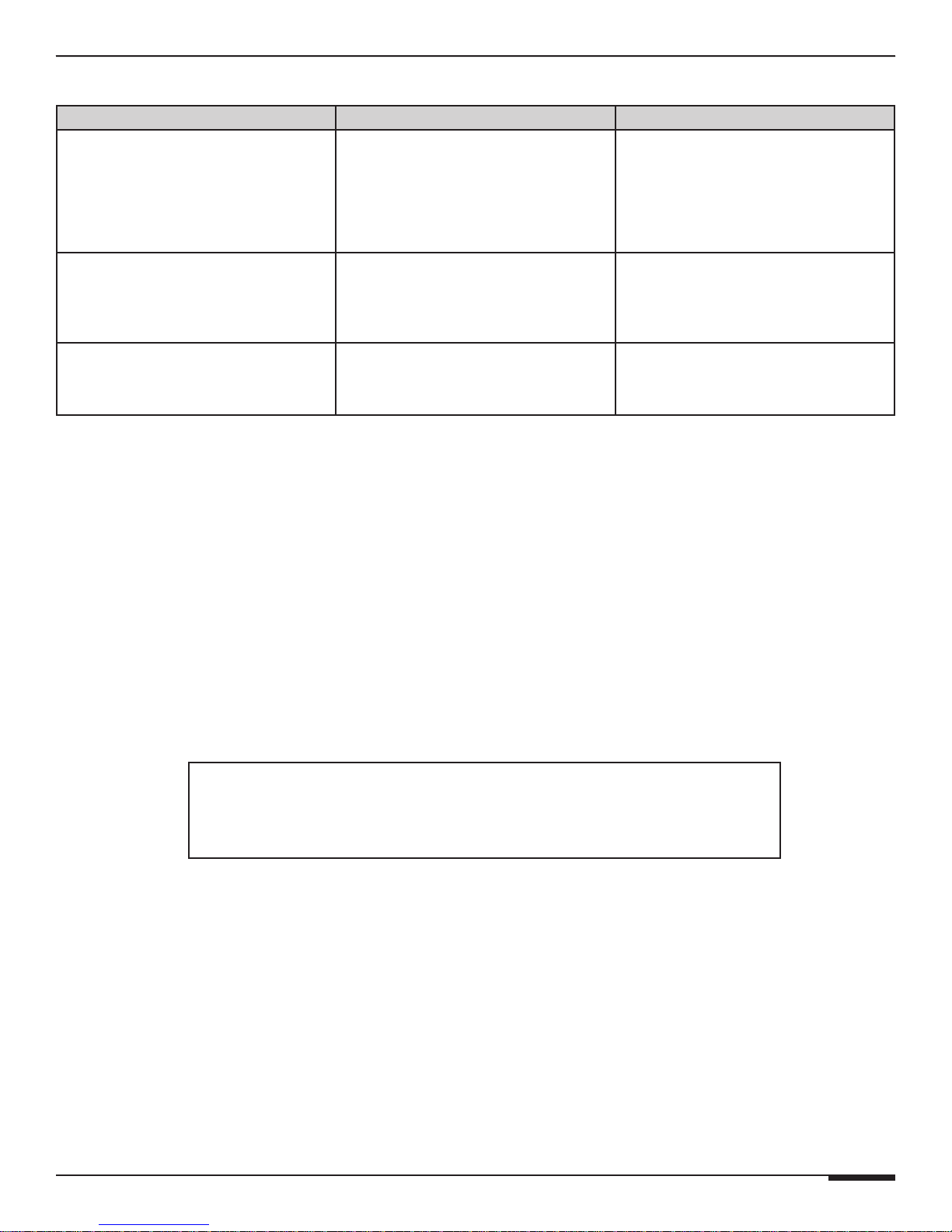
Table 5-3: IR Control
Symptom Possible Cause Solution
IR LED does NOT flash
when a button pressed.
1. IR controller not programmed.
2. IR signal path wiring bad.
Program IR controller.
Verify IR signal path wiring.
Check keypads, IR sensors, IR
distribution blocks, IR Input
jack, IR emitters, etc.
A6 INSTALLATION MANUAL
No channel selected
from IR controller.
IR LED DOES flash when
button pressed.
Intermittant or no control from IR controller. IR LED on LCD flickers or is lit
constantly.
1. Incorrect IR commands
programmed).
2. Chassis codeset incorrect.
IR flooding. Check IR receivers for ambient light or
Verify/correct IR programming.
Verify/correct IR programming.
plasma TV flooding.
Technical Support
If, after carefully following the steps in the Troubleshooting section, you are
unable to resolve issues with the installation or operation of the A6, please call
ELAN Technical Support at 1-800-622-ELAN (3526).
© ELAN Home Systems 2009 • All rights reserved. Page 23
Page 32
A6 INSTALLATION MANUAL
E L A N H O M E S Y S T E M S
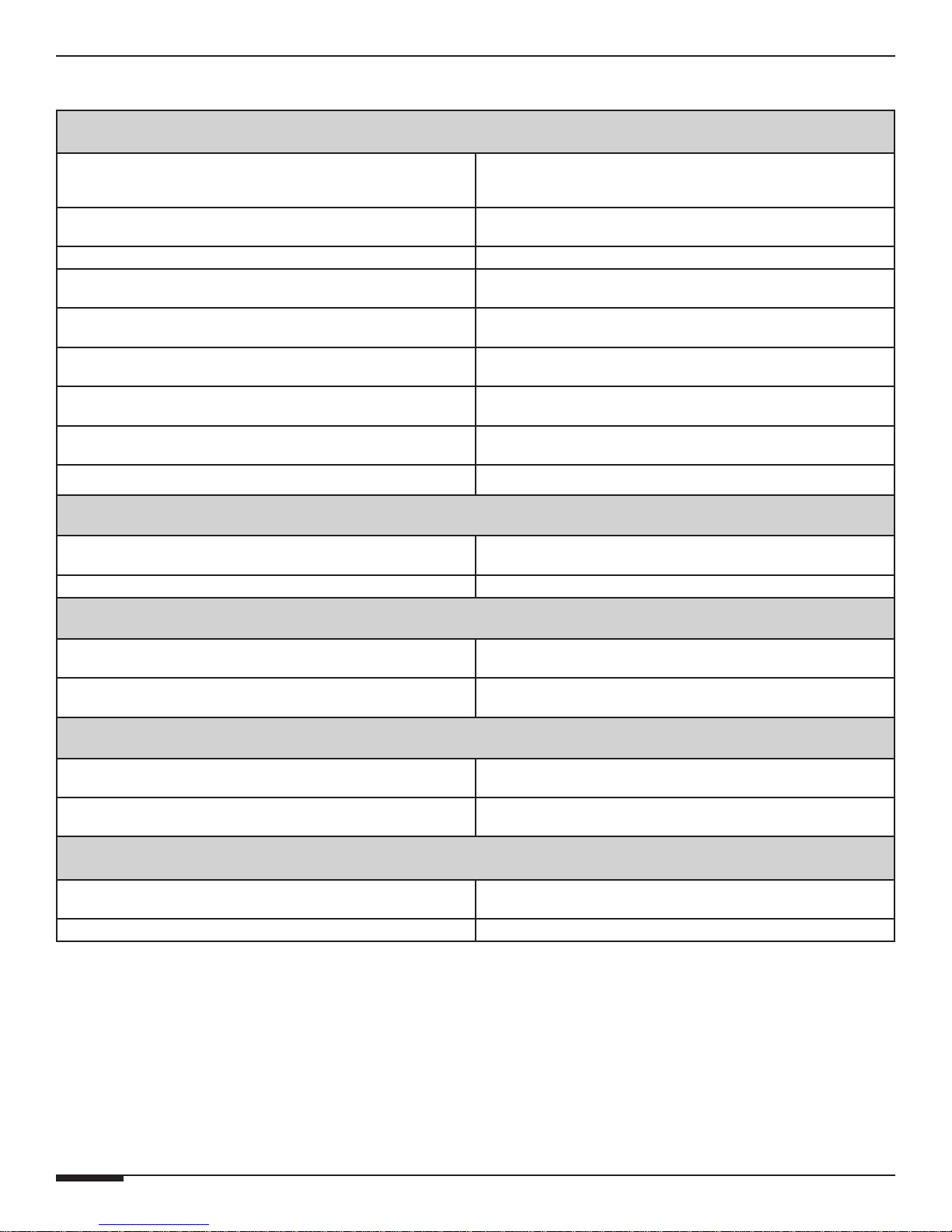
Appendix A: Specifications
Audio Section
Power Rating - Output Power 60WPC RMS @ 8 Ohms
120WPC RMS @ 8 Ohms Bridged
Frequency Response 20Hz to 20kHz, -.25dB
Full Power Bandwidth 5Hz to 30kHz
Signal-To-Noise > 110dB (A-weighted)
Channel Separation >70dB @1kHz
Total Harmonic Distortion < 0.03%
Intermodulation Distortion < -90dB
Voltage Gain (AV) 0 - 20 front panel adjustable
Input Impedance 20k Ohms
Connectors
Input/Loop Outputs Gold RCA Phono
Speaker Outputs Gold 5 Way Binding Posts
Power
AC Power Requirements A6-120 VAC, 440 Watts
Current Draw 3.7A @ 120VAC
Triggers
Remote Trigger Inputs 5 to 24V AC/DC
Remote Trigger Outputs +12 VDC @0.1A
Dimensions/Weight
Dimensions w/ Feet (1U w/o Feet) 17 W x 2 1/4 H x 11 D (in)
432 W x 58 H x 280 D (mm)
Weight 16 lbs/7.2 kg
Page 24 © ELAN Home Systems 2009 • All rights reserved.
Page 33
E L A N H O M E S Y S T E M S
A6 INSTALLATION MANUAL
Appendix B: Rack Mounting
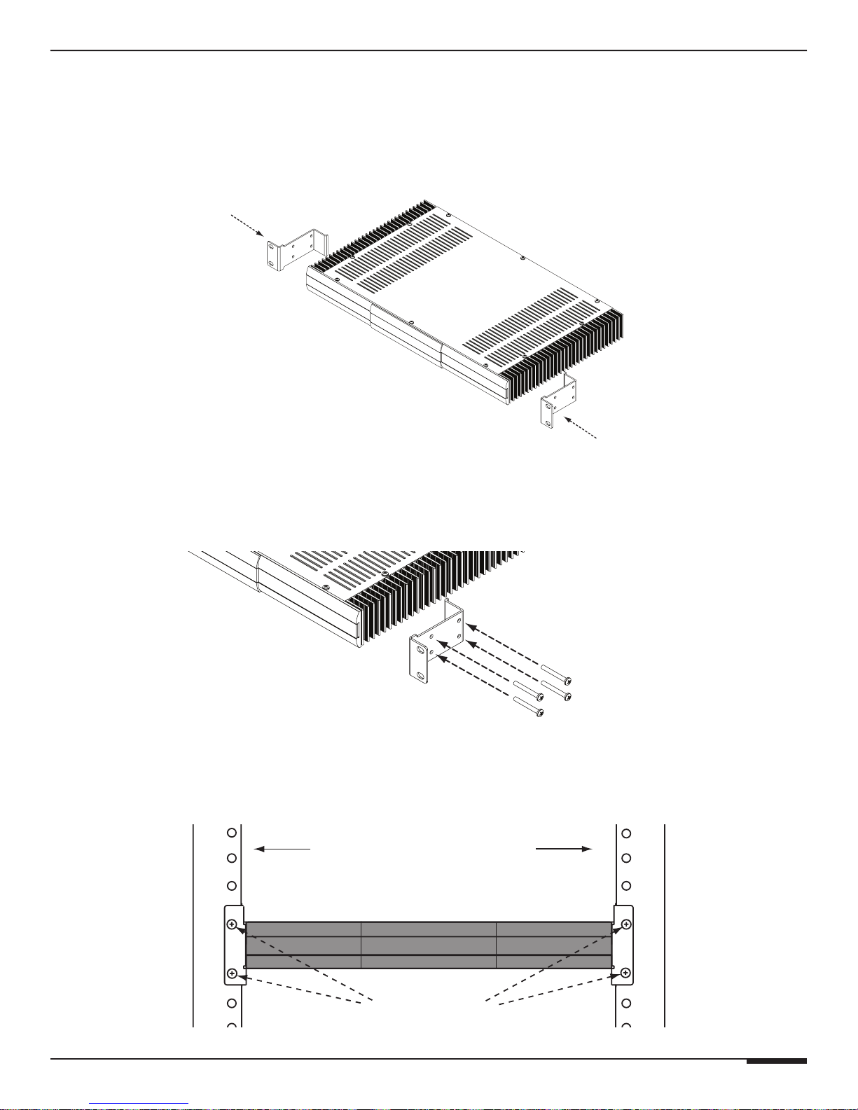
Rack-Mount Brackets
When mounting the A6 amplifier in an equipment rack, use the included rack mount brackets for secure mounting
and proper ventilation. The A6 requires one rack space, ensure that one rack space above and below the A6 is left
open for proper ventilation. To install the A6 into a standard 19” equipment rack:
1. Slide the rack mount kit onto the A6 chassis from the front as shown in Figure B-1.
Figure B-1
2. Ensure that the unit is flush with the front of the mounting kit. Install each of the eight screws (included) through
the side mounting flanges into the holes in the sides of the unit as shown in Figure B-2. Hand tighten screws!
Over-tightening could cause damage to the A6 Amplifier.
Figure B-2
3. Once the unit is securely mounted onto the rack mount brackets, install the entire assembly into a standard 19”
equipment rack from the front using four rack screws (not included) as shown in Figure B-3.
19" Equipment Rack
© ELAN Home Systems 2009 • All rights reserved. Page 25
Rack Screws
Figure B-3
Page 34

A6 INSTALLATION MANUAL
Notes:
E L A N H O M E S Y S T E M S
Page 26 © ELAN Home Systems 2009 • All rights reserved.
Page 35

Page 36

Limited Warranty
ELAN HOME SYSTEMS L.L.C. (“ELAN”) warrants the ELAN A6 Six Channel Amplifier to be free from defects in materials
and workmanship for the period of two years (2 years) from date of purchase. If within the applicable warranty
period above purchaser discovers that such item was not as warranted above and promptly notifies ELAN in
writing, ELAN shall repair or replace the item at the company’s option. This warranty shall not apply (a) to
equipment not manufactured by ELAN, (b) to equipment which shall have been installed by other than an
ELAN authorized installer, (c) to installed equipment which is not installed to ELAN’s specifications, (d) to equipment
which shall have been repaired or altered by others than ELAN, (e) to equipment which shall have been subjected to
negligence, accident, or damage by circumstances beyond ELAN’s control, including, but not limited to, lightning,
flood, electrical surge, tornado, earthquake, or other catastrophic events beyond ELAN’s control, or to improper
operation, maintenance or storage, or to other than normal use of service. With respect to equipment sold by, but
not manufactured by ELAN, the warranty obligations of ELAN shall in all respects conform to the warranty actually
extended to ELAN by its supplier. The foregoing warranties do not cover reimbursement for labor, transportation,
removal, installation or other expenses which may be incurred in connection with repair or replacement.
Except as may be expressly provided and authorized in writing by ELAN, ELAN shall not be subject to any other
obligations or liabilities whatsoever with respect to equipment manufactured by ELAN or services rendered by ELAN.
THE FOREGOING WARRANTIES ARE EXCLUSIVE AND IN LIEU OF ALL OTHER EXPRESSED AND IMPLIED
WARRANTIES EXCEPT WARRANTIES OF TITLE, INCLUDING BUT NOT LIMITED TO IMPLIED WARRANTIES OF
MERCHANTABILITY AND FITNESS FOR A PARTICULAR PURPOSE.
ATTENTION: TO OUR VALUED CONSUMERS
To ensure that consumers obtain quality pre-sale and after-sale support and service, ELAN Home Systems products
are sold exclusively through authorized dealers. ELAN products are not sold online. The warranties on ELAN products
are NOT VALID if the products have been purchased from an unauthorized dealer or an online E-tailer. To determine
if your ELAN reseller is authorized, please contact ELAN Home Systems at (859) 269-7760.
www.elanhomesystems.com
www.elanhomesystems.com
Lexington, KY
P/N 9900992 REV:A
 Loading...