

Page 1
ELAFLEX PACIFIC PTY LTD · Unit 29 / 58 Box Road · Taren Point · NSW 2229 · Australia
Tel. +61 2 8058 9258 · info@elaflex.com.au · www.elaflex.com.au
INSTALLATION AND OPERATING MANUAL
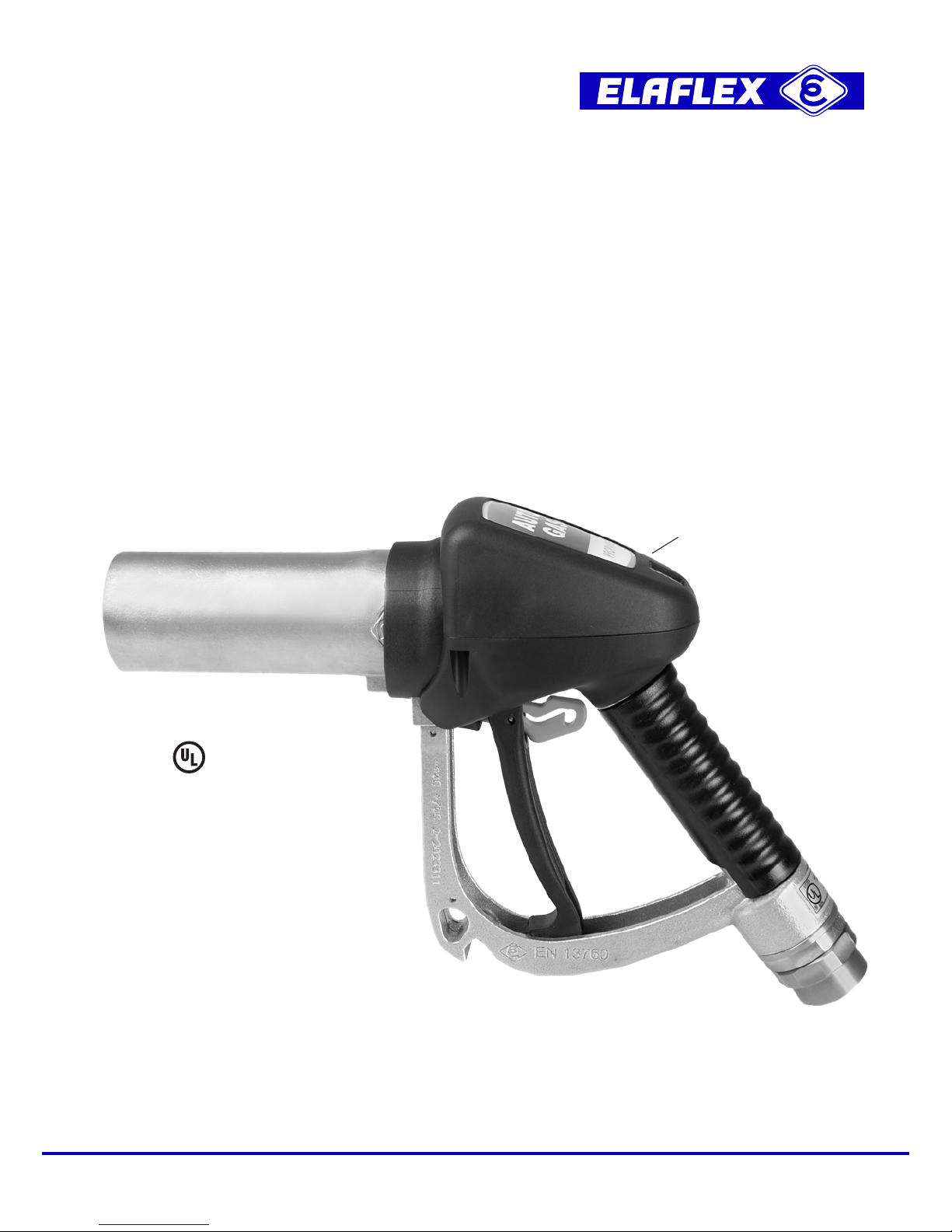
ZVG 2 EURO UL
LPGas Nozzle with 'EURO' Connector
9 / 2018
Underwriters
Laboratory listed
Meets EN 13760 /
UN R 67 / ISO 19825
Picture shows
optional Scuguard
( Nozzle Talker ) EA 866
Page 2
Please read this manual carefully before installation or operation of the nozzle.
Be sure all instructions are understood. Correct installation, use and maintenance are essential.
In case of doubt or question please contact your service contractor or the manufacturer.
DESCRIPTION
The ZVG 2 EURO UL nozzle is designed for the LPGas vehicle refueling. Unlike the previously used LPGas nozzles with screw-on connectors, it is equipped with a 'EURO' coupling and optionally with an orange safe latching mechanism to increase user comfort as
per UL 125. It incorporates ease of use, operating safety and low gas release volume upon
uncoupling. The nozzle is designed to only allow gas to flow when it is correctly coupled.
APPROVALS / OPERATING CONDITIONS
ZVG 2 EURO UL is listed by Underwriters Laboratories for use with LPGas (Liquefied Petroleum Gas like propane, butane and their mixtures). It also meets the requirements of EN 13760,
UN R67 and ISO 19825.
Flowrate up to 50 litres/min. Rated service pressure 363 psi (25 bar), operation tempera ture range
-40° F (-40° C) to 131° F (70° C). Test pressure 544 psi (37.5 bar), burst pressure in excess of 1450
psi (100 bar). Each nozzle is factory tested before being labelled with the prescribed marking,
production date and unique serial number.
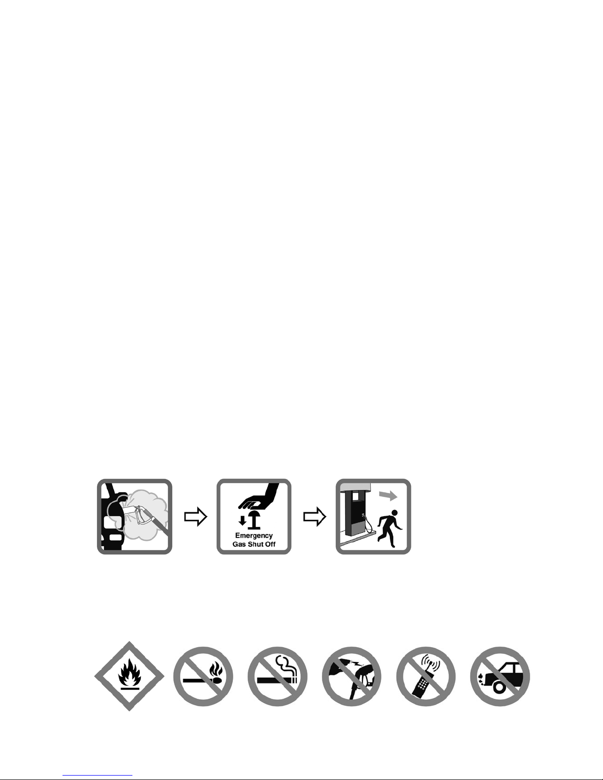
GENERAL INFORMATION ABOUT LPG / WARNINGS
• LPGas is liquefied under pressure when transported and stored. It is heavier than air.
Commercial LPGas is odourised before distribution to enable detection by its sulfurous smell.
It appears as white fog or cloud when exposed to the atmosphere. It has an evaporation factor
of 1/260: one liter of liquefied gas corresponds to 260 liters of inflammable gas.
A small gas release upon uncoupling is normal – but uncontrolled gas release to
the atmosphere must be avoided. If you suspect a leakage: stop refueling, use the
emergency button to shut o the dispenser, immediately evacuate the area and
inform station personnel.
• LPGas is extremely flammable, which is capable of igniting at concen tra tions between 2 and
10 % in air.
Open fires, smoking, sources of static electricity and the use of mobile phones
or other electric devices is prohibited in the area of gas transfer. Turn o vehicle
engine before refueling.
symbol icon
escaping gas
2
Page 3
• LPGas is extremely cold when released to the air (depressurized).
Local laws and code of practice regarding LPGas handling as well as instructions of vehicle,
dispenser and authorized personnel must be followed. Please also refer to the safety codes
NFPA 54 + 58 and NPGA 306.
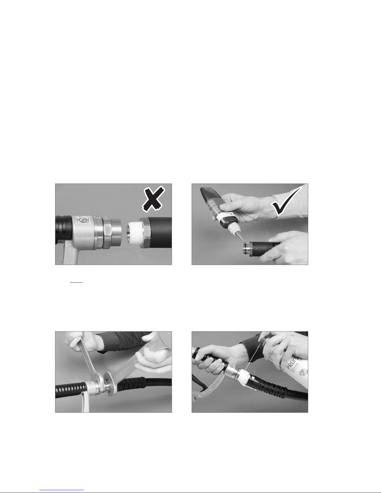
INSTALLATION
The ZVG 2 EURO UL is delivered ready for use.
Nozzles should only be installed and tested by competent personnel. Applicable laws, regulations
and Codes of Practice have to be followed.
Do not use PTFE sealing tape for sealing threaded connections, as electrical conductivity may be
insucient and particles of the tape commonly become loose and could clog the nozzle strainer
or damage vehicle motor parts. Use suitable liquid seal (non permanent) instead.
Do n o t use PTFE tape Use liquid seal (non permanent)
After connecting to the hose assembly, an operational test shall be performed. It is essential to
examine that the nozzle, hose connector and swivel are tight under pressure and do not leak –
e. g. by external application of foaming agents.
Assemble with spanners Check tightness
3
Page 4

OPERATING INSTRUCTIONS
Please follow any additional
or deviating operating
instructions displayed
at the dispenser.
Ensure that all coupling parts,
seals and sealing surfaces of
nozzle and vehicle coupling are
clean and undamaged.
Switch o vehicle engine.
Take nozzle from dispenser. If
necessary activate the dispen-
ser. Align nozzle with vehicle si-
ded fill point as shown.
Remove nozzle and take it back
to its parking position on the
dispenser.
Push nozzle firmly onto the
vehicle fill point.
OFF
Fueling will now usually start.
If leakage is observed, release
lever to stop process.
Do not lean on / tilt the nozzle.
On completion of refueling
release lever to disconnect. If
latch is fitted, squeeze lever and
latch will automatically release.
During lever release a quantity
of liquid gas is discharged
from front of the nozzle.
If the vehicle is equipped with
an integrated EURO coupling
this will be a small amount.
If an adapter is used this will be
a considerably larger amount.
To avoid cold burns, keep
hands o the coupling area.
Pull nozzle lever as shown to
open the nozzle valve. If latch is
fitted, push latch up with forefinger and release lever.
4
Page 5

FILL POINT ADAPTORS
The use of fill point adaptors is not recommended by ELAFLEX PACIFIC PTY LTD.
If an adaptor is used, please note:
• During the release of the nozzle lever at the end of the fueling process, a quantity of liquid
gas remaining between vehicle fill point and nozzle is discharged. When using adaptors,
the released volume of gas is much greater compared to a direct connection with the
vehicle filling connector.
• Replace worn out adaptors (tears, breaks, cuts, damaged sealing surface).
MALFUNCTION
• If the lever cannot be pulled back
Check the correct seating of the nozzle to the vehicle coupling. A safety feature prevents
operation of the nozzle if the connection is misaligned. If you have any doubts or questions, please contact the station personnel.
Never force operation of the nozzle. If the connection process does not work smoothly,
disconnect and re-connect nozzle as indicated under chapter 'Operation'.
• Leakage ( escaping gas )
A small gas release upon uncoupling is normal. If uncontrolled and / or permanent gas
release to the atmosphere occurs, immediately stop fueling. If the leakage continues,
push emergency button of dispenser, leave area and inform station personnel.
If area is safe, check tight connection between vehicle connection and ZVG 2 EURO UL
nozzle and coupling. Check seals of vehicle connection and ZVG 2 EURO UL coupling.
If the problem persits notify the station personnel or the service contractor.
MAINTENANCE
The ZVG 2 EURO UL nozzle is a mechanical device that may become inoperative due to wear,
corrosion and ageing of components. Regular inspections and maintenance are essential for a
safe operation.
Daily visual inspections of the nozzle by trained personnel should be carried out to ensure
proper function. The nozzle coupling shall be clean and not show any signs of damage (e. g. dents,
sharp edges, blocked lever, swivel non rotating). Especially check the red coloured front seal
inside the coupling part of the nozzle to confirm there is no dirt or mechanical damage.
The nozzle condition shall be thoroughly checked during the annual pump maintenance by competent personnel. Applicable laws, regulations and Codes of Practice have to be followed.
Nozzles in unfit condition for use must be immediately replaced.
5
Page 6

CONDITIONS OF USE
Failure to comply with any warnings, instructions, procedures or any other common sense
procedures may result in injury, equipment damage, property damage or poor performance of
the equipment.
ELAFLEX PACIFIC PTY LTD accepts no liability for direct, indirect, incidental, special, or consequential damages resulting from failure to follow any warnings, instructions and procedures in
this manual, or any other common sense procedures generally applicable to equipment of this
type. The foregoing limitation extends to damages to person or property caused by the unit or
damages resulting from the inability to use the unit including loss of profits, loss of products, loss
of power supply, the cost of arranging an alternative power supply, and loss of time, whether
incurred by the user or their employees, the installer, the commissioner, a service technician, or
any third party.
The manufacturer reserves the right to change the specifications of its products or the information
in this manual without necessarily notifying its users.
Variations in installation and operating conditions may aect the unit‘s performance. ELAFLEX
PACIFIC PTY LTD has no control over each installation‘s unique operating environment. Hence, no
representations or warranties concerning the performance of the unit under the actual operating
conditions prevailing at the installation are made. A technical expert of your choosing should
validate all operating parameters for each application.
ELAFLEX PACIFIC PTY LTD has made every eort to explain all servicing procedures, warnings,
and safety precautions as clearly and completely as possible. However, due to the range of
operating environments, it is not possible to anticipate every issue that may arise. This manual
is intended to provide general guidance. For specific guidance and technical support, contact
your authorized supplier.
Only approved original parts shall be used and no unauthorized modifications to the hardware
shall be made. The use of non-approved parts or modifications will void all warranties and
approvals. The use of non-approved parts or modifications may also constitute a safety hazard.
Information in this manual shall not be deemed a warranty, representation, or guarantee. For
warranty provisions applicable to this unit, please refer to the warranty provided by the supplier.
Every eort has been made to ensure the accuracy of this document. However, it may contain
technical inaccuracies or typographical errors. ELAFLEX PACIFIC PTY LTD assumes no responsibility for and disclaims all liability of such inaccuracies, errors or omissions in this.
WARRANTY
ELAFLEX PACIFIC PTY LTD guarantee against defective materials and manufacturing for
18 months from date of supply. If the delivery date cannot be established, the factory date code
on the nozzle guard applies ( e. g. •18 = 1st quarter 2018 ).
Excluded are nozzles and parts subjected to wear and tear and damages caused by improper
use, for example the use with unsuitable fluids. Furthermore excluded are indirect damages and
costs, such as travelling related to exchange and repair work. We refuse any liability for consequential loss or damage resulting from the use of our nozzle.
6
Page 7

7
Page 8

8
Complete operating instructions see page 4 of this manual. Follow any additional or
deviating instructions displayed at dispenser.
STOP FUELING
START FUELING
Latching
Unlatching
 Loading...