

Page 1
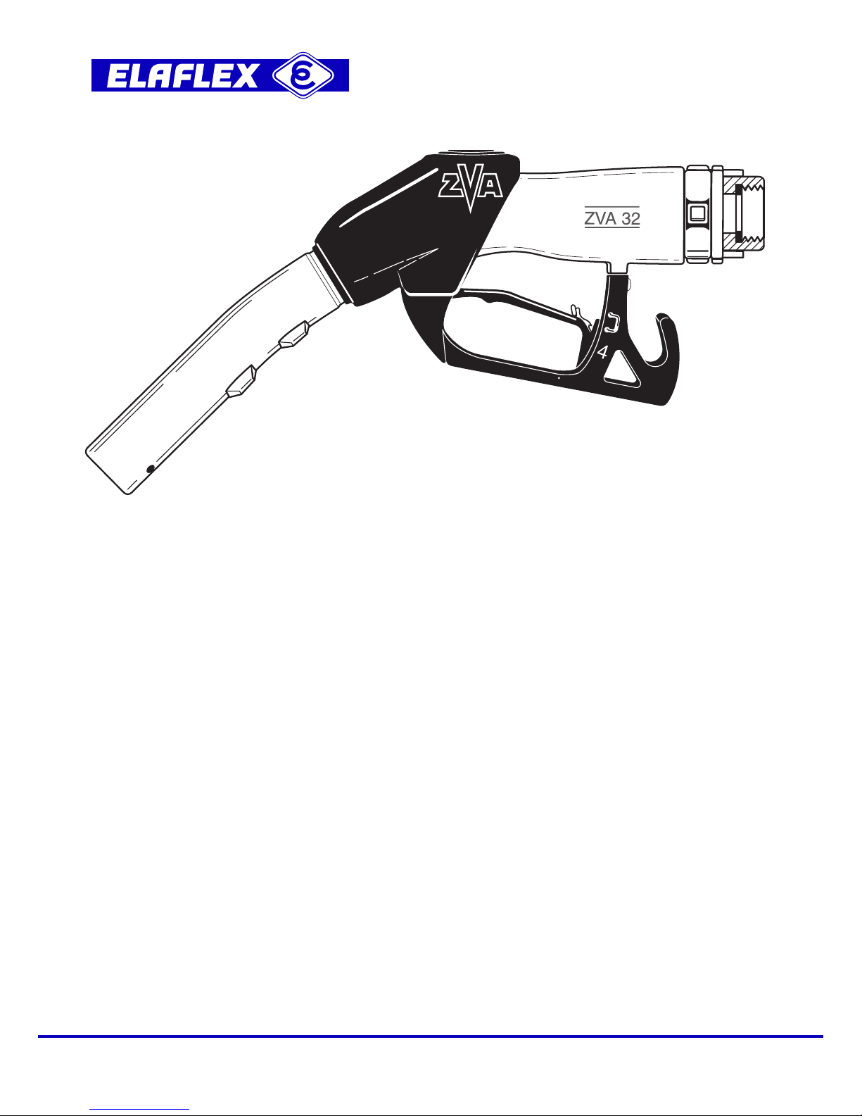
ZVA 32
11/4"
EN 13012
TÜV P-TÜ7-00512
SIRA 03ATEX9 487 U
(
`
II 1G
)
AUTOMATIK - ZAPFVENTIL ZVA 32 deutsch
MONTAGE- UND BEDIENUNGSANLEITUNG Seite 2
AUTOMATIC SAFETY NOZZLE ZVA 32 english
INSTALLATION AND OPERATING INFORMATION
page 4
ROBINET AUTOMATIQUE DE SECURITE ZVA 32
français
INSTRUCTIONS DE MONTAGE ET D’EMPLOI page 6
PISTOLA AUTOMATICA DI SICUREZZA ZVA 32 italiano
MONTAGGIO E MANUTENZIONE pagina 8
BOQUEREL AUTOMATICO DE SEGURIDAD ZVA 32
español
INSTRUCCIONES DE MONTAJE Y DE USO página 10
АВТОМАТИЧЕСКИЙ РАЗДАТОЧНЫЙ КРАН ZVA 32
русский
УКАЗАНИЯ ПО МОНТАЖУ И ПРИМЕНЕНИЮ стр. 12
ELAFLEX HIBY Tanktechnik GmbH & Co. KG · 22525 Hamburg / Germany
Schnackenburgallee 121 · Tel. +49 40 - 540 00 50 · Fax +49 40 - 540 00 567
5.2018
Page 2

3
HINWEISE ZUR RICHTIGEN BEDIENUNG
STECKEN SIE DAS ZAPFROHR TIEF IN DEN TANK. Die Kugel des Sicherheits-
auslösers ( 3 ) rollt nach vorn und gibt die Fühlerleitung frei. So tanken Sie richtig.
HÄNGEN SIE DAS ZAPFROHR SICHER IM FÜLLSTUTZEN EIN, damit das ZVA nicht
während des Betankens herausrutschen kann.
Da A bei einigen flachen Füllstutzen nicht möglich ist, verhindert der Sicherheitsauslöser das
Tanken in dieser Position. Die Kugel rollt nach hinten und sperrt die Fühlerleitung ab.
Das Zapfventil schaltet dauernd ab.
Bei der Situation B ist das Anheben des Zapfventils von Hand erforderlich, damit die
Kugel nach vorn rollt und die Fühlerleitung önet. Das Tanken ist jetzt möglich, wenn
das Zapfventil in dieser Lage gehalten wird.
FÜLLEN SIE NICHT ZU SCHNELL, sonst lösen Kraftstospritzer die Abschalt-Automatik
aus, bevor der Tank gefüllt ist. - Einige Füllstutzen lassen sich schlecht befüllen. Reduzieren Sie die Füllgeschwindigkeit, um ein Herausspritzen von Kraftsto durch zurückdrängende Gasblasen (blow back bzw. spit back) zu verhindern. Die drei Stufen der
Aufhalteraste ( 7 ) ermöglichen ein Anpassen an die Aufnahmefähigkeit jedes Einfüllstutzens:
obere Stufe 3/3 = hohe Durchflussrate für große steile Einfüllstutzen
mittlere Stufe 2/3 = reduzierter Durchfluss für engere Einfüllstutzen
untere Stufe 1/3 =
niedrigerer Durchfluss für Einfüllstutzen mit schlechter Entlüftung
Hinweis: Bei leichtem Ziehen des Schalthebels önet sich nur das Pilotventil des ZVA 32,
Leistung bis 60 l/min. Bei weiterem Ziehen des Schalthebels önet sich das Hauptventil und
gibt den maximalen Volumenstrom frei.
AUCH BEIM NACHTANKEN KLEINER MENGEN VON HAND schaltet die Automatik gemäß
EN 13012 ab, wenn der Kraftsto die Fühlerdüse (1) verschließt. Das Nachtanken ist möglich.
LASSEN SIE DAS ZAPFVENTIL GUT AUSTROPFEN: Bei automatischer Abschaltung wird
etwas Kraftsto in die Fühlerleitung ( 2 ) eingesaugt. Neigen Sie das ZVA immer einige
Sekunden zum Tank, bevor Sie es in die Zapfsäule zurückhängen. Dann wird der nächste
Benutzer nicht durch herauslaufende Kraftstoreste überrascht.
BITTE BEACHTEN
Das ZVA 32 ist zugelassen für Kraftstoe in einem Druckbereich von 1,5 bis 6 bar und Abgabeleistung bis maximal 200 Liter/Minute. Bei Drücken oberhalb von 6 bar önet das ZVA selbsttätig. Wenn das ZVA für andere Zwecke wie z. B. einen abweichenden Druckbereich oder für
andere Flüssigkeiten als zugelassen eingesetzt werden soll, ist vorher Rückfrage mit Angabe
der genauen Betriebsbedingungen erforderlich.
GARANTIE
Für Material- und Fabrikationsfehler leisten wir Garantie bis zu 18 Monaten nach Lieferdatum.
Wenn das Lieferdatum nicht zweifelsfrei festzustellen ist, gilt das am Bügelnocken eingegossene
Quartals- und Jahresdatum (z.B.
·
18 = 1. Quartal 2018).
Ausgenommen von der Garantie sind Zapfventile, die durch äußere Verschleißbeanspruchung
oder durch Benutzung für ungeeignete Flüssigkeiten und Zusätze unbrauchbar geworden sind.
Nicht ersatzpflichtig sind Montage- und Wegekosten im Zusammenhang mit Austausch und
Reparatur sowie Körper- und Sachfolgeschäden aus dem Gebrauch der Zapfventile.
A
B
C
D
Zeichenerklärung Seite 16
2
INBETRIEBNAHME
Das ZVA 32 ist ein Vollschlauch-Zapfventil mit automatischer Abschaltung für die Kraftsto-
Betankung (Diesel, Heizöl EL und Flugtreibstoe) durch elektrisch betriebene Zapfsäulenpumpen
für maximal 200 Liter/Minute, Druckbereich 1,5 - 6 bar Betriebsdruck.
Das ZVA 32 erfüllt EN 13012 und die europäischen Eichbestimmungen. TÜV-Zulassung und
ATEX-Zertifikat ( Kategorie Ex II 1G ) siehe Seiten 14 - 15.
Jedes Zapfventil wird vor Verlassen des Werkes unter erschwerten Bedingungen einer Stückprüfung unterzogen und mit der vorgeschriebenen Kennzeichnung sowie Herstelldatum und Herstellungsnummer versehen.
Das ZVA 32 wird betriebsfertig geliefert. Nach Montage am Schlauch und Einschalten der Pumpe
durch mehrfaches Betätigen des Schalthebels ( 9 ) den Schlauch entlüften und wie folgt prüfen:
ob Zapfventil, Drehgelenk und Schlauchanschluss unter Druck einwandfrei dicht sind?
ob die elektrische Ausschaltung der Pumpe beim Einhängen in die Zapfsäule funktioniert
WARTUNG
Die Konstruktion ermöglicht es, auf eine Schmierung der beweglichen Teile der AbschaltAutomatik zu verzichten, weil diese vom Kraftsto umspült werden.
Sicherheitsüberwachung: Durch regelmäßige Sichtkontrolle muss der äußere Zustand des
Zapfventils überwacht werden. Dabei ist besonders darauf zu achten, ob die Rasten des Zapfrohres ein sicheres Einhängen im Füllstutzen gewährleisten. Bei Defekten, die das Vakuum
beeinträchtigen können, mindestens aber mit der jährlichen Zapfsäulenwartung müssen die
'Minimal-Abschaltung' und die Funktion des Kugelkipp-Sicherheitsauslösers (3) überprüft werden.
BEI STÖRUNGEN
WENN DIE AUTOMATIK VERSAGT, ist meistens das Vakuum zur Betätigung der Abschalt-
Automatik nicht hoch genug. Bei voll gezogenem Schalthebel ( 9 ) prüfen, ob die Pumpe genügend
Kraftsto fördert. Auch prüfen, ob der Vakuumabfall eventuell durch ein gelockertes
Auslaufrohr, undichten Membrandeckel ( 5 ) oder verstopftes Grobsieb ( 8 ) verursacht wird.
WENN DAS ZVA IMMER ABSCHALTET, ist meistens die Fühlerleitung ( 2 ) verschlossen. Zuerst
prüfen, ob dies nicht durch die Kugel des Sicherheitsauslösers (3) verursacht wird. Beim Schütteln
des Ventils kann man hören, ob sich die Kugel bewegt. Zur Kontrolle der Fühlerleitung Druckluft
von vorn in das Zapfrohr blasen, bis ein feiner Luftstrahl aus der Fühlerdüse ( 1 ) austritt.
WENN SELBSTHILFE NICHT MÖGLICH, die nächste ZVA-Servicefirma benachrichtigen.
SO FUNKTIONIERT DIE AUTOMATIK
Der Kraftstofluß erzeugt am Ventilsitz ( 6 ) ein Vakuum. Durch die Fühlerleitung ( 2 ), die bis zur
Fühlerdüse ( 1 ) führt, wird zum Ausgleich des Vakuums Luft angesaugt. Solange die Fühlerdüse
frei bleibt, kann das Zapfventil arbeiten. Wenn Kraftsto die Fühlerdüse bedeckt, wird die
Luftzufuhr unterbrochen. Sofort baut sich das Vakuum auf und die Membrane ( 4 ) löst den
Abschaltmechanismus aus. Die Abschalt-Automatik wird auch ausgelöst, wenn die Fühler leitung
durch die Kugel des Sicherheitsauslösers ( 3 ) verschlossen wird. Das geschieht, wenn das
Zapfrohr nach oben gerichtet wird oder wenn das ZVA auf den Boden fällt.
Zeichenerklärung Seite 16
Page 3

5
HINTS FOR PROPER HANDLING
INSERT THE SPOUT FULLY INTO THE TANK. The ball of the safety valve rolls forward
to open the safety cut out. This is the best way to fuel.
MAKE SURE THAT THE ZVA IS HOOKED FIRMLY INTO THE FILL PIPE so that it cannot
slip out during refuelling.
With some near horizontal fill pipes version A is not possible. The safety cut-out attitude
valve prevents the valve from opening. The ball rolls backwards blocking the sensing
path and the nozzle trips o continuously.
With situation B lift and hold the nozzle so that the ball now rolls forward opening up the
air passage. Refuelling is now possible provided the nozzle is kept in this position.
DO NOT FILL TOO FAST : Splashing fuel can trip the nozzle before the tank is full.
Some filler necks are dicult to refuel. Fuel at lower speeds to avoid fuel blow backs. The
flowrate can be adapted to the capacity of the filler neck by the three - speed lever latch ( 7 ).
First position 3/3 = Fully opened for straight and near vertical fill pipes
Middle setting 2/3 = Reduced output for narrower fill pipes
Lower position 1/3 = Slow position for poorly vented pipes
Note : when the lever is pulled slightly only the pilot valve of the ZVA 32 opens - flowrate
up to 60 litres/min. Further pulling of the lever opens the main valve for maximum flowrate.
THE AUTOMATIC SHUT OFF WILL ALSO WORK IF THE LEVER IS HELD OPEN MANUALLY,
according to EN 13012. Once the fuel touches the sensing port (1) the automatic cuts o. Topping
up is possible.
A FEW DROPS OF FUEL WILL REMAIN IN THE NOZZLE SENSING PORT. Always tilt
the nozzle forward into the tank to drain for a few moments before returning it to the nozzle
boot. Then the next user will not be surprised by drips
.
PLEASE NOTE
The ZVA 32 is approved for fuels in a pressure range of 1,5 - 6 bar and flowrate up to 200 litre/
minute. The ZVA opens automatically when the pressure exceeds 6bar. If it is intended to use it
for other applications you should consult your supplier who will
be pleased to advise its suitability
on receipt of full details, including fluid, and operating conditions.
GUARANTEE
We guarantee against defective materials and manufacturing up to 18 months from date of supply.
If the delivery date cannot be established, the date code on the nozzle (e.g.
·
18 = 1st quarter 2018)
prevails. Excluded are nozzles and parts subjected to wear and tear, abuse and to contamination.
Furthermore excluded are damages by misuse, indirect damages and costs, travelling related to
exchange and repair work. We refuse any liability for consequential loss or damage resulting from
the use of our nozzle.
A
B
C
D
Description see page 16
4
PUTTING INTO SERVICE
The ZVA 32 is a fuel-dispensing nozzle for diesel, light fuel oil and aviation fuels. With automatic
shut o, for wet-hose use with electrically operated petrol dispensing pumps for a maximum of
200litres/minute, pressure range 1,5 - 6 bar.
The ZVA 32 fulfils the conditions of the European Weights and Measures as well as EN 13012.
TÜV approval and ATEX certicate ( category Ex II 1G ) see pages 14-15.
Each nozzle has been subjected to stringent tests before leaving the factory and
validated by the
applied markings and date code.
The ZVA 32 is supplied ready for connection to the hose. After assembling and switching on the
pump operate the lever ( 9 ) several times to vent air from the hose. Then check :
Is the nozzle, hose connection and swivel tight under pressure?
Does the pump switch o when putting the nozzle back into the nozzle boot?
MAINTENANCE
The nozzle does not require any lubrication.
Safety checks: Regularly inspect the nozzle visually for damage. Pay attention that the spout
serration secures the nozzle in the filler neck. Test the 'minimum' shut o and the safety cut o
function ( 3 ) during the annual pump maintenance and instantly in case of damages which may
eect the vacuum.
IN CASE OF TROUBLE
IF THE NOZZLE DOES NOT CLOSE AUTOMATICALLY usually the vacuum required to operate
the automatic action is too low. With the pump running, fully pull the lever ( 9 ) to check that full
flow can be obtained. Also check, if a loose spout, damaged vacuum cap ( 5 ) or clogged strainer ( 8 )
have caused the pressure drop.
IF THE ZVA KEEPS TRIPPING OFF PERMANENTLY the air passage ( 2 ) is blocked.
First check if it is caused by the ball of the safety cut o, by shaking the nozzle. If the ball is free
to move, it will rattle. To clear the air passage, blow compressed air through the spout until air
comes out of the sensing port ( 1 ).
IF YOU CANNOT MAKE IT WORK please call your service contractor. They have the skills and
parts needed to restore working order.
HOW THE ZVA AUTOMATIC WORKS
The flow through the nozzle creates a vacuum at the valve seat ( 6 ). Air is drawn in through the
sensing port ( 1 ) at the tip of the spout, through the safety cut-out, past the diaphragm, and into
the fuel. The valve will remain open while the air flows freely. When fuel reaches the sensing
port, a vacuum builds up rapidly until it lifts the diaphragm ( 4 ) and trips the automatic action which
shuts the valve. The mechanism also trips if the ball of the safety cut-out ( 3 ) rolls back to
obstruct the free air flow. This will occur if the spout is pointed upwards or if the nozzle is
dropped onto the ground.
Description see page 16
Page 4

7
CONSEILS POUR LA BONNE UTILISATION
INTRODUISEZ LE TUBE D’ECOULEMENT A FOND DANS LE RESERVOIR. La bille
de sécurité ( 3 ) se place à l’avant et libère le canal. Le remplissage est alors possible.
ACCROCHEZ LE TUBE D’ECOULEMENT CONVENABLEMENT SUR LA TUBULURE
D’ENTREE DU RESERVOIR, pour éviter qu’il ne s’échappe pendant le remplissage.
Du fait de ce qui est exposé au paragraphe A, le ravitaillement n’est pas possible avec
certaines tubulures d’entrée plates, la bille de sécurité empêche le ravitaillement en cette
position. La bille se place à l’arrière et bloque l’arrivée d’air. Le robinet se coupe sans cesse.
Dans ce cas il est nécessaire de soulever le robinet à la main pour que la bille de sécurité
roule vers l’avant et libère le canal. Le ravitaillement est maintenant possible si le robinet
est maintenu dans cette position.
NE REMPLISSEZ PAS TROP VITE, sinon, les éclaboussures de carburant peuvent
provoquer l’arrêt automatique avant la fin du remplissage. Certaines tubulures de
remplissage sont diciles à ravitailler. Réduisez le débit pour éviter des éclaboussures
de carburant ou des bulles de gaz (blow back). Les trois positions du levier ( 7 ) permettent
d’adapter le débit de ravitaillement du réservoir:
Cran supérieur
3/3 = débit maximum pour tubulures verticales et de grand diamètre
Cran intermédiaire 2/3 = env. 2/3 du débit pour tubulures étroites
Cran inférieur 1/3 = env. 1/3 du débit pour tubulures mal aérées
Remarque: Une pression légère sur la poignée du pistolet n’ouvre que la vanne pilote du
ZVA 32. Il en résulte un débit jusqu’à 60 litres/min. Une pression plus forte ouvre la vanne
complètement et permet une livraison optimale.
EN COMPLETANT LE "PLEIN" A LA MAIN, l’arrêt automatique fonctionne également selon
l’EN 13012 lorsque le carburant obture la bouche du canal d’air (1). Vous pouvez donc sans
crainte remplir jusqu‘au bord ou au centime près.
LAISSEZ S’EGOUTTER LE ROBINET: Lors de l’arrêt automatique une certaine quantité de
carburant remonte dans le tube ( 2 ). Maintenez toujours le robinet sur l’orifice du réservoir
quelques secondes avant de le raccrocher sur le distributeur. La personne qui s’en servira
ensuite ne sera pas surprise par l’écoulement du carburant résiduel.
ATTENTION
Le ZVA32 est adapté à l’essence et carburants automobiles. Sa plage de pression de service va
de 1,5 à 6 bar, le débit maximum est de 200 l /min. En cas d’une surpression superieure à 6 bar
le robinet s’ouvre automatiquement. Si le ZVA 32 doit être utilisé pour d’autres fonctions, comme
par ex. une plage de pression diérente ou pour des produits non autorisés, il est nécessaire de
vous renseigner en indiquant les conditions d’utilisation exactes.
GARANTIE
La garantie couvre des défauts de matériaux et de fabrication pour une durée allant jusqu ’ à 18
mois à compter de la date de livraison. Dans le cas ou la date de livraison n’est pas déterminée,
la date de fabrication indiquée sur le corps (example
·
18 = 1er quartier 2018) fait foi. Sont exclues
de la garantie des pièces rendues inutilisables à cause d’une mauvaise utilisation ou par
l’usage du pistolet pour des produits non appropriés. Sont également exclus de la garantie,
les frais de dépose ou de réparation, les frais de déplacement ainsi que tout dédommagement
pour accident causé à quiconque ou dommages corporels et matériels consécutifs.
A
B
C
D
Détails des renvois page 16
6
MISE EN ROUTE
Le ZVA 32 est un pistolet de distribution pour diesel, fioul léger et carburant aviation avec arrêt
automatique pour le ravitaillement par un volucompteur pour un débit maximal de 200 litres/
minute et une pression de service entre 1,5 et 6 bar.
Le ZVA 32
répond aux réglementations métrologiques européennes et EN 13012. Homologation
TÜV et certificat ATEX (catégorie Ex II 1G) voir pages 14-15.
Chaque robinet est avant son départ de l’usine soumis à un contrôle individuel dans des conditions
sévères. Il est ensuite doté de son marquage,
ainsi que de la période de fabrication et de son
numéro de série.
Le ZVA 32
est livré prêt à l’emploi. Après le montage et l’installation de la pompe presser
plusieur fois la poignée ( 9 ) pour évacuer l’air du flexible. Il convient de vérifier:
Si le robinet, le raccord du flexible et le raccord tournant sont entièrement étanches
lorsqu’ils sont mis sous pression,
Si l’arrêt électrique de la pompe fonctionne lors du raccrochage du pistolet sur la borne de
distribution.
CONTRÔLE
Sa construction permet de renoncer au graissage de toutes les pièces en mouvement du
dispositif automatique d’arrêt du fait qu’elles se trouvent nettoyées et lubrifiées en permanence
par le produit luimême.
Surveillance de la sécurité : Par un contrôle visuel régulier, surveiller l’état extérieur du
pistolet. Lors de la maintenance annuelle du distributeur de carburant ou lors d’une défaillance
du robinet, les fonctions de sécurité (arrêt automatique à faible débit, bille de sécurité ( 3 ) )
doivent être vérifiées.
EN CAS DE PANNES
LORSQUE LA FERMETURE AUTOMATIQUE NE FONCTIONNE PAS, c’est souvent la dépression
n’est pas susamment élevée pour actionner la fermeture automatique. Il convient donc de
vérifier, si la pompe refoule susamment de carburant, si le manque de dépression n’est
éventuellement pas due à un desserrement du tube d’écoulement, à une mauvaise étanchéité du
couvercle de membrane ( 5 ) ou à un encrassement du filtre ( 8 ).
LORSQUE LE ZVA S’ARRETE TOUJOURS, c’est souvent le canal de détection ( 2 ) qui est
obstrué. Il convient alors de vérifier si cela n’a pas été provoqué par la bille de sécurité. En
secouant le robinet on peut entendre si la bille bouge. Pour le contrôle du canal de détection, il
sut d’insuer de l’air comprimé dans le tube d’écoulement. Un jet d’air très fin doit ressortir
par la bouche du canal de détection ( 1 ).
SI VOUS N’ARRIVEZ PAS A VOUS DEPANNER, adressez-vous au service d’entretien qualifié
le plus proche.
FONCTIONNEMENT DE L’AUTOMATISME
Le débit du carburant produit une dépression au niveau du siège de clapet ( 6 ). L’air est aspiré
par l’entrée de la bouche du canal de détection pour compenser la dépression. Dès que le
liquide vient obstruer la bouche du canal, l’arrivée d’air est interrompue. Un vide se crée instantanément et la membrane ( 4 ) déclenche la fermeture automatique. Le même eet est produit
quand la bille de sécurité ( 3 ) vient à obstruer le canal. Lorsque le tube est orienté vers le haut ou
si le pistolet tombe sur le sol.
Détails des renvois page 16
Page 5

9
CONSIGLI PER UN CORRETTO USO:
Introducete profondamente il beccuccio nel bocchettone. La sfera della valvola di
sicurezza si sposta in avanti e permette l’entrata dell’aria. Così si può iniziare.
Agganciate la pistola perfettamente nel bocchettone per evitare che possa cadere
durante il rifornimento.
Per alcuni tipi di bocchettoni quasi orizzontali, la valvola di sicurezza evita il rifornimento.
La sfera si sposta indietro e blocca l’entrata dell’aria. La pistola scatta continuamente.
Con la situazione B é necessario alzare la pistola fino a quando la sfera va in avanti. Il
rifornimento é ora possibile se si tiene la pistola con la mano in qs. posizione.
Non riempite troppo in fretta, altrimenti lo spruzzo di carburante aziona la chiusura
automatica prima che il serbatoio sia pieno. In presenza di vetture con bocchettoni
dicoltosi, riducete la portata per evitare la fuoriuscita di carburante. Con le tre posizioni
del fermo ( 7 ) della leva potete adattare la portata ad ogni tipo di bocchettone:
alta posizione 3/3 = alta portata per grossi bocchettoni verticali
media posizione 2/3 = media portata per bocchettoni più stretti
bassa posizione 1/3 = bassa portata per bocchettoni con uno sfiato irregolare
Alzano lievemente la leva si apre solamente la valvola pilota della ZVA 32; si ottiene una
portata fino a 60 l/min. Alzando ulteriormente la leva si apre la valvola principale aumentando
il flusso fino alla massima portata.
L’ARRESTO AUTOMATICO FUNZIONA ANCHE PER EROGAZIONI MANUALI A BASSA
PORTATA, in accordo a EN 13012, quando il carburante occlude il foro di controllo livello (1).
Potete cosi rifornire sino all’orlo del serbatoio o fare cifra tonda.
LASCIARE SGOCCIOLARE BENE LA PISTOLA AUTOMATICA. Nel fermarsi
automaticamente il canale ( 2 ) risucchia un pò di carburante. Inclinatela sempre qualche secondo
verso il serbatoio, prima di riagganciarla alla colonna. Si evita cosi lo sgocciolamento per il
prossimo cliente.
ATTENZIONE
La ZVA 32 é omologata per carburanti alla pressione tra minimo 1,5 e mass. 6 bar fino ad una
portata di max. 200 l/min. Con troppa pressione, oltre 6 bar, la ZVA si apre automaticamente. Se la
pistola viene usata per altri liquidi oppure per un’altra pressione, Vi preghiamo di richiedere presso
la ns. sede informazioni, specificandone l’uso preciso.
GARANZIA
Garantiamo per un tempo di 18 mesi dopo la data di consegna per ogni ZVA che rivela difetti
di materiale o di costruzione. Se la data di consegna non é chiara vale la data stampata nel corpo
ZVA, (per esempio · 18 = 1. trimestre 2018).
Sono esenti da garanzia interventi non autorizzati e danni causati da abusi come l’uso per liquidi
e additivi non adatti. - Sono esclusi tutti i costi indiretti ed i danni conseguenti. Per questo non
siamo obbligati al risarcimento delle spese di montaggio, cosi come degli elementi e dei danni
causati dall’uso della pistola ZVA.
A
B
C
D
Spiegazioni pag. 16
8
MESSA IN FUNZIONE
La ZVA 32 è una pistola automatica con arresto di sicurezza per erogazione di gasolio, olio
combustibile leggero e carburanti aerei. Adatta all’utilizzo con distributori azionati elettricamente
ha una portata massima di 200 litri / minuto e una pressione d’esercizio compresa tra 1,5 e 6 bar.
Ogni ZVA 32 viene rigorosamente controllata prima di uscire dalla fabbrica e reca, come
prescritto, il contrassegno con il numero di serie, trimestre ed anno di fabbricazione. Corrisponde
a standard EN 13012. Omologazione sec. TÜV e certificato ATEX ( categoria Ex II 1G ) vedasi pag.
14-15.
La pistola ZVA 32 viene fornita pronta per essere montata sul tubo d’erogazione. Dopo la messa
in moto della pompa, azionando la leva di comando ( 9 ), fare fuoriuscire l’aria e controllate:
Che la pistola e l’attacco al tubo d’erogazione siano ben chiusi.
Che funzioni l’interruttore della pompa agganciando la pistola al distributore.
MANUTENZIONE
Questa pistola brevettata permette di rinunciare a qualsiasi ingrassaggio. Tutte le sue parti
movibili vengono lubrificate dal carburante: Con questo sistema di autopulizia e
autolubrificazione non necessita alcuna manutenzione alle parti interne, anche per anni.
Consigli per la sicurezza: Tramite un controllo regolare del corpo esterno si verifica la condizione della ZVA. Verificate se é possibile agganciare bene il beccuccio nel bocchettone. In caso di
difetti, oppure almeno una volta all’anno si dovrebbe controllare lo scatto durante la
portata minima ed il funzionamento della valvola di sicurezza ( 3 ).
IN CASO DI INCONVENIENTI
SE NON FUNZIONA IL SISTEMA AUTOMATICO, vuol dire che non si è creato abbastanza vuoto per
il suo azionamento. Controllate, con la leva di comando ( 9 ) completamente aperta, se la pompa manda
carburante a sucienza e se il filtro ( 8 ) è libero. Controllate anche se la mancanza di vuoto è dovuta al
fatto che il beccuccio non è ben fissato, oppure se il tappo della membrana ( 5 ) ha delle perdite.
SE LA PISTOLA ZVA SCATTA, spesso può essere a causa della chiusura del foro controllo
livello ( 1 ). Controllate, poi, che la sfera della valvola di sicurezza si muova - (scuotendo la
valvola la si può sentire). La pulizia del beccuccio con canale ( 2 ) si eettua con aria a pressione
soandola nella bocca del beccuccio finchè dal foro controllo livello ( 1 ) non esca un filo d’aria.
Togliete anche, con un filo di ferro molto sottile, eventuali particelle di sporco.
SE NON VI È POSSIBILE FARE DA SOLI avvertite la ditta di assistenza della ZVA. Questa
tiene a disposizione: personale qualificato, pezzi originali di ricambio e, il più delle volte,
provvede alla sostituzione della pistola stessa.
FUNZIONAMENTO
Il carburante passando nella sede valvola ( 6 ), crea un’aspirazione d’aria all’altezza della
strozzatura. Tramite il canale ( 2 ) che va dall’interno della pistola, alla membrana, alla valvola di
sicurezza, e che termina al foro controllo livello, viene aspirata aria per riequilibrare il vuoto.
La pistola automatica lavora solamente se tale foro è libero. Se il livello del carburante supera il foro
all’estremità del beccuccio, si interrompe l’alimentazione dell’aria e si forma immediatamente un vuoto:
la membrana ( 4 ) si solleva e si aziona il fermo automatico. Il fermo automatico si aziona anche
quando la sfera della valvola di sicurezza ( 3 ) ottura il foro.
Ciò avviene sempre quando la pistola è rivolta verso l’alto: per esempio quando non si tiene
rivolta bene verso il basso durante il rifornimento, quando scivola fuori dal serbatoio, quando
viene azionata per sbaglio la leva di comando nel prendere la pistola dal distributore.
Spiegazioni pag. 16
Page 6

11
RECOMENDACIONES PARA EL MANEJO CORRECTO
INTRODUZCA EL TUBO DEL BOQUEREL LO MAS PROFUNDAMENTE POSIBLE EN
LA BOCA DE LLENADO DEL DEPOSITO. La valvola de bola ( 3 ) se encuentra delante y
permite la entrada de aire. De esta forma está Vd. repostando correctamente.
COLOQUE EL BOQUEREL BIEN EN LA BOCA DE LLENADO, para que durante el
repostamiento el ZVA no pueda soltarse.
En el caso de no realizar la indicación anterior, el boquerel cierra constantemente,
debido a que en su desplazamiento hacia atrás, la válvula de bola impide la entrada de
aire y el boquerel cierra de forma automática.
En este caso es necesario levantar el boquerel, para que en su desplazamiento hacia
delante la válvula de bola permita la entrada de aire y puede realizarse la operación de
repostado.
NO LLENE EL DEPOSITO DEMASIADO RAPIDO, ya que las salpicaduras o formación
de espuma del combustible activan el cierre automático antes del llenado total
del depósito. - En bocas que por su posición o tamaño se encuentre dificultad al
repostar, reduzca la velocidad de llenado, para lo cual el gatillo del boquerel dispone de
un trinquete ( 7 ) adaptado a tres posiciones que regulan el caudal del suministro.
Posición superior 3/3 =
Caudal máximo para depósitos verticales y bocas de entrada
amplias.
Posición mediana 2/3 =
de caudal para entradas de depósitos más estrechas.
Posición baja 1/3 = de caudal reducido para depósitos con entradas de mala
ventilación.
INCLUSO REPOSTANDO PEQUEÑAS CANTIDADES MANUALMENTE, el sistema automático
activa el cierre según EN 13012, si el combustible está tapando el sensor (1). El repostamiento
sigue siendo possible.
AL TERMINAR DE LLENAR EL DEPOSITO ESPERE EN LA POSICION DE SUMINISTRO
HASTA QUE EL BOQUEREL DEJE DE GOTEAR. Por el cierre automático en el tubo sensor
( 2 ) se almacena un poco de combustible. Mantenga inclinado el ZVA algunos segundos hacia
el depósito antes de volver a colgarlo en el aparato surtidor. De esta manera, el siguente
usuario no se encontrará con los restos de combustible que salen del boquerel.
IMPORTANTE
El ZVA 32 es apropiado para combustibles, para presiones de trabajo comprendidas entre 1,5 y
6 bar y suministro hasta 200 l/min. Con sobrepresión de 6 bar el boquerel abre automáticamente.
Cuando el ZVA deba ser utilizado en aplicaciones distintas a las de diseño, como por ejemplo
presión y líquidos diferentes a los descritos, rogamos nos consulten indicando las condiciones
exactas de trabajo.
GARANTIA
El boquerel ZVA está garantizado contra todo defecto de material o de fabricación hasta
18 meses después de la fecha de suministro exceptuando las piezas expuestas al desgaste o por
uso indebido. En el caso de no poder demostrar la fecha de suministro, se tomará como
correcto la indicación que figura grabada en el protector del gatillo (ejemplo: · 18 = 1. trimestre 2018).
Quedan excluidos de la garantía gastos de montaje (mano de obra) y desplazamiento
respecto a la sustitución así como todo daño que pudiera resultar del uso normal del boquerel.
A
B
C
D
Ver página 16
10
PUESTA EN MARCHA
El ZVA 32 es un boquerel de sistema de manguera llena para diésel, aceite combustible y combustible para aviación. Con cierre automático para el repostamiento de combustible utilizado en
aparatos surtidores, para presiones de trabajo comprendidas entre 1,5 y 6 bar fino a 200 l/min.
El ZVA 32 cumple con las normas de calibración europeas así como con el reglamento de
seguridad según EN 13012. Homologación TÜV y certificado ATEX ( categoria Ex II 1G ) ver
páginas 14-15.
El ZVA 32 se suministra en condiciones para ser conectado al racor de la manguera. Después
de su montaje y puesta en marcha de la bomba con el fin de eliminar el aire debe apretarse el
gatillo ( 9 ) varias veces y comprobar:
Si el boquerel y la conexión entre el racor de manguera y el racor giratorio son estancos.
Si al el corte de suministro eléctrico al motorfuncion.
MANTENIMIENTO
Gracias al diseño del boquerel no es necesario engrasar las partes móviles del cierre automático,
ya que éstas están bañadas por el combustible produciendo un efecto de autolimpieza y lubricación.
Control de seguridad: El estado exterior del boquerel tiene que ser vigilado regularmente. Hay
que asegurarse que las levas del tubo se permitan colgar correctamente el boquerel en la
boquilla del tanque. En caso de defectos que puedan influir el corte automático, pero como
mínimo de forma regular durante el control anual, hay que controlar el corte automático así como
la función de la válvula de bola ( 3 ).
EN CASO DE ANOMALIAS
CUANDO EL SISTEMA AUTOMATICO FALLA, el vacío para la activación del cierre automático
no es lo suficientemente alto. Apretando el gatillo ( 9 ) del todo hay que comprobar si la bomba
suministra suficiente combustible y si la malla filtrante ( 8 ) está limpia. Comprobar además si el
caño del boquerel está suelto o el tapón de la membrana ( 5 ) flojo.
SI EL ZVA SE PARA SIEMPRE, en la mayoría de los casos es el tubo sensor ( 2 ) que está
obstruido. Primero se debe comprobar si la causa es la bola de seguridad (al agitar el boquerel
se oye si la bola se mueve). Para comprobar el tubo sensor hay que inyectar de frente aire en el
tubo de salida, hasta que salga por el orificio sensor ( 1 ).
EN CASO DE NO PODER SOLUCIONAR VD. EL PROBLEMA, rogamos contacte con el
servicio técnico autorizado.
ASI FUNCIONA EL CORTE AUTOMATICO
El suminstro de combustible produce un vacío en el asiento de la válvula ( 6 ). Para compensar
este vacío entra aire a través del tubo sensor ( 2 ), que llega hasta el orificio sensor ( 1 ). Mientras
éste permanece libre, el boquerel puede suministrar. - Cuando el combustible obtura el orificio
sensor se interrumpe la entrada de aire. En seguida se forma un vacío y la membrana ( 4 ) pone
en marcha el mecanismo de cierre.
En el caso de que la válvula de bola de seguridad ( 3 ) cierre la conexión con el tubo sensor ( 2 ),
igualmente provoca un corte automático. Esto sucede cuando el boquerel se sitúa en posición
vertical o se cae al suelo.
Ver página 16
Page 7

13
УКАЗАНИЯ ДЛЯ ПРАВИЛЬНОГО ИСПОЛЬЗОВАНИЯ
ГЛУБОКО ОПУСТИТЕ ЗАПРАВОЧНЫЙ НОСИК В ТОПЛИВНЫЙ БАК. Шарик
клапана отсечки топлива ( 3 ) двигается вперед и открывает канал отсечки. Это
правильный способ заправки.
ПРОЧНО УСТАНОВИТЕ ЗАПРАВОЧНЫЙ НОСИК В ЗАПРАВОЧНУЮ ГОРЛОВИНУ
ТОПЛИВНОГО БАКА, чтобы ZVA не мог выпасть во время заправки.
Так как пункт A не применяется для некоторых плоских заправочных горловин,
устройство безопасности препятствует заправке в этой позиции. Шарик двигается
назад и закрывает канал отсечки. Раздаточный кран постоянно отключается.
При ситуации B необходимо приподнять раздаточный кран вручную, чтобы шарик смог
двигаться вперед и открыть канал отсечки. Заправка возможна при такой позиции
раздаточного крана.
НЕ ЗАПРАВЛЯЙТЕ СЛИШКОМ БЫСТРО, иначе брызги топлива могут привести
в действие механизм автоматического отключения, а бак еще не наполнился.
Некоторые заправочные горловины не удобны для заправки. Снизьте мощность
подачи, чтобы избежать брызгов из-за обратно поступающих пузыриков газа (blow
back или spit back). 3-уровневый фиксатор позволяет применение заправочного
штуцера любой мощности:
верхний уровень 3/3 = полная мощность для больших крутых заправочных горловин
средний уровень 2/ 3 = средняя мощность для более узких заправочных горловин
нижний уровень 1/3 = слабая мощность для заправ. горловин с плохой деаэрацией
Указание: при легком нажатии рычага открывается только пилотный раздат. кран
ZVA 32 с мощностью потока 60 л/мин. При усиленном нажатии на рычаг
открывается
основной раздат. кран и подает поток топлива полной мощности.
ДАЖЕ ПРИ МАЛОЙ ДОЗАПРАВКЕ ВРУЧНУЮ автоматическое отключение крана срабатывает
согласно европейскому стандарту EN 13012, когда уровень топлива в баке достигает кончика
носика раздаточного крана. Дозаправка возможна.
ХОРОШО ОПОРОЖНИТЕ РАЗДАТОЧНЫЙ КРАН: при автоматическом отключении немного
топлива остается в канале отсечки ( 2 ). Поэтому наклоните ZVA на несколько секунд к баку,
прежде чем повесить его назад на ТРК. Так следующий водитель не будет иметь остатков
топлива, стекающего с крана еще до заправки.
ОБРАТИТЕ ВНИМАНИЕ
ZVA 32 имеет аттестацию для топлива в диапазоне давления 1,5 - 6 бар и мощности потока 200
л/мин. ZVA открывается самостоятельно. Если ZVA будет использоваться для других целей,
как, например, при ином давлении или для других веществ, не указанных в его аттестации,
необходимо проконсультироваться с поставщиком.
ГАРАНТИЯ
Мы гарантируем качество изготовления и материалов в течение 18 месяцев с момента
поставки. Если дата поставки не ясна, найдите на скобе квартал и год изготовления
(например,
·
18 = 1-й квартал 2018).
Гарантия не распространяется на раздаточные краны, которые износились с внешней
стороны или применялись для неподходящих средств и добавок.В гарантийные расходы
не входят затраты на монтаж и транспорт с целью замены или ремонта раздаточных
кранов, а также возмещение ущерба в случае повреждения физических лиц или вещей в
результате использования раздаточных кранов.
A
B
C
D
Объяснение знаков - стр. 16
12
ВВОД В ЭКСПЛУАТАЦИЮ
Раздаточный кран ZVA 32 для дизельного топлива, легкого жидкого топлива и виационного
топлива, с автоматической отсечкой для подачи топлива из электрической
топливозаправочной колонки с макс. мощностью 200 л / мин, диапазон рабочего давления
1,5 - 6 бар.
ZVA 32 соответствует стандарту калибровки Германии и правилам безопасности EN 13012.
Аттестация TÜV и ATEX ( категории Ex II 1G ) - на стр. 14-15.
ZVA 32 поставляется готовым к использованию. После установки и подсоединения крана
к ТРК, нажмите несколько раз на рычаг ( 9 ), чтобы откачать воздух из шланга, и проверьте:
плотно ли соединены раздат. кран, шланг. соединение и поворотная муфта под давлением?
функционирует ли электрическое отключение насоса при установке раздаточного крана
обратно на ТРК?
ОБСЛУЖИВАНИЕ
Благодаря своей конструкции раздат. кран не требует смазки подвижных деталей
автоматического отключения, так как они омываются и смазываются протекающим горючим.
Контроль безопасности: регулярно проверяйте раздаточный кран на внешние
повреждения. Особое внимание обратите на то, гарантируют ли позиционирующие
выступы безопасное фиксирование раздаточного носика в горловине топливного бака.
В случае возникновения повреждений, которые могут нарушить герметичность, или,
по крайней мере, в рамках ежегодного обслуживания, необходимо проводить
“минимальное отключение” и проверку функции клапана отсечки топлива ( 3 ).
ПРИ ПОВРЕЖДЕНИЯХ
ЕСЛИ ZVA НЕ ОТКЛЮЧАЕТСЯ АВТОМАТИЧЕСКИ, чаще всего это происходит из-за
давления, которого не хватает для включения автоматики. Нажимая рычаг ( 9 ) до упора,
проверьте достаточно ли топлива подает насос ТРК. Также проверьте, упало ли
давление из-за разболтавшегося заправочного носика, неплотно установленной
диафрагмы ( 5 ) или засоренного ситечка-фильтра ( 8 ).
ЕСЛИ ZVA ПОСТОЯННО ОТКЛЮЧАЕТСЯ, чаще всего это происходит из-за того, что
засорен канал отсечки ( 2 ). Сначала проверьте, не обусловлено ли это наличием шарика
безопасности в канале отсечки топлива. При встряхивании раздаточного крана слышно,
двигается ли шарик. Для контроля канала отсечки ( 2 ) необходимо выдуть сжатый воздух
через заправочный носик, пока воздух не выйдет через датчик отсечки ( 1 ).
ЕСЛИ САМОСТОЯТЕЛЬНО НЕ СПРАВИТЬСЯ, обратитесь в сервисную фирму.
ТАК ДЕЙСТВУЕТ АВТОМАТИКА
Течение топлива через раздат. кран создает вакуум в клапане ( 6 ). Сквозь канал отсечки ( 2 ),
который тянется до датчика отсечки ( 1 ), всасывается воздух. Раздат. кран работает до
тех пор, пока датчик отсечки свободный. Если топливо покрывает его, поступление воздуха
прекращается. Сразу образуется вакуум и диафрагма ( 4 ) приводит механизм автоматического
отключения в действие. Кран отключается, шарик клапана отсечки топлива ( 3 ) закрывает
канал отсечки. Механизм также срабатывает, когда запр. носик направлен вверх или при
падении крана на землю.
Объяснение знаков - стр. 16
Page 8

14
ATEX certicate · certicat ATEX · certicato ATEX · certicado ATEX · Аттестация ATEX
PDF download: http://www.elaflex.de/zertifikate · http://www.elaflex.de/en/certificates
TÜV approval · Homologation TÜV · Omologazione TÜV · Homologación TÜV · Аттестация TÜV
PDF download: http://www.elaflex.de/zertifikate · http://www.elaflex.de/en/certificates
15
Page 9

1
2
3
4
5 6 8
9
7
3/3
2/3
1/3
16
A
C
B
D
 Loading...