

Page 1
Die 2 Montagehilfsschrauben durch 4 Standard-Stahlschrauben*) ersetzen, über Kreuz
anziehen, einige Stunden setzen lassen.
Erst danach gegen mitgelieferte Edelstahlschrauben austauschen – so werden
'Fresser' von Schrauben/Muttern vermieden.
6
' FLUORFLEX 2 '
Montage · Assembly
Mai 2009
FLUORFLEX 2 Montage · Assembly
Montierte Schlauchleitungen sollen vor dem Einsatz druckgeprüft
werden (Prüfdruck 24 bar, Betriebsdruck bis 16 bar). Ferner muss
die Leitfähigkeit gemessen werden (s. Merkblatt BG Chemie T002).
Prior to first use, hose assemblies should be pressure tested
(test pressure 24 bar, working pressure up to 16 bar).
Further, the electrical conductivity has to be checked.
F
luorflex Schlauchstutzen Edelstahl 1.4571
Fluorflex hose tail stainless steel 1.4571
(FX ... VST)
F
luorflex Spannschalen Edelstahl 1.4408 /
Schrauben + Muttern Edelstahl 1.4401
Fluorflex hose clamps stainless steel 1.4408 /
bolts + nuts stainless steel 1.4401
(FX-SC ... SS)
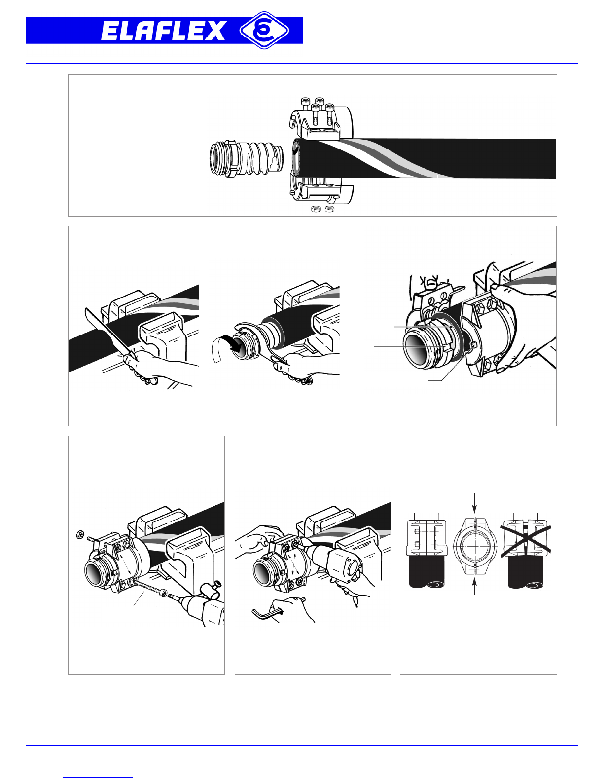
Schlauch gerade einspannen und
mit scharfem Schlauchmesser gerade
ablängen.
Fluorflex Schlauchstutzen mit dem
Hakenschlüssel einschrauben, bis
der Haltekragen mit der Schlauchschnittfläche bündig ist (Bild 4).
Alle Schraube n vor der Montage am
Gewinde einfetten. Schalen mit 2 längeren
Montagehilfsschrauben*
)
gleichmäßig über
Kreuz anziehen.
Nach der Endmontage muss der verbleibende
Spalt zwischen beiden Schalen parallel und
beidseitig gleich groß verlaufen.
Fluorflex Schlauch - siehe Info 2.08
Fluorflex hose - see Info 2.08
(FXD ...)
Clamp hose straight. Cut with a sharp
knive straight / at an right angle.
Using a hook spanner, screw Fluorflex
hose tail into hose – until thread collar
is even with cut hose end (picture 4).
Position Fluorflex hose clamps. The cams on the front side
of the clamps fit in the grooves of the hose tail. Only use
special Fluorflex hose clamps.
Nocken (Verdrehsicherung)
Cam (Anti-twist protection)
Nut
Groove
Fluorflex-Schalen anlegen. Die Nocken der Halbschalen
passen in die Nuten des Stutzens. Nur Spezial Fluorflex-
Armaturen verwenden.
After assembly the eventual remaining space
between the clamps should be parallel.
1
23 4
5 7
Haltekragen
thread collar
*
) siehe Katalog Seite 297 / see catalogue page 297
Montagehilfschrauben
Assembly bolts
Grease all bolt/nut threads prior to assembly.
First use 2 long auxiliary screws*), thighten
evenly/crosswise.
Remove 2 auxiliary screws. To avoid seizure
of bolts, first use 4 standard steel bolts*) and
tighten crosswise. Leave it for setting for
some hours. Then change bolts/nuts against
supplied stainless steel bolts/nuts.
Page 2
Fluorflex Schlauchstutzen Edelstahl 1.4571
F
luorflex hose tail stainless steel 1.4571
(
FX ... VST)
' FLUORFLEX 2 ' + KSS
Montage / Assembly
FLUORFLEX 2 + KSS Montage · Assembly
Mail 2009
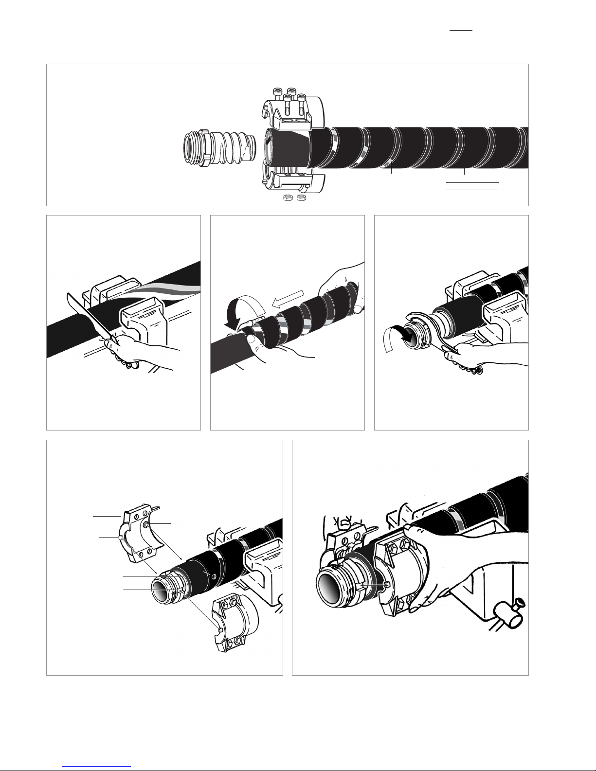
Schlauch gerade einspannen, mit scharfem
Schlauchmesser gerade ablängen.
Zur Positionierung die Knickschutzspirale am
Ende anfassen und gegen den Uhrzeigersinn
verdrehen.Wichtig:zwischen denWindungen
der Knickschutzspirale am Ende der Montage
(Bild 6) 1 - 2 cm Platz lassen, um im
Betrieb ausreichende Biegung
zu gewährleisten.
Fluorflex Schlauchstutzen mit Hakenschlüssel
einschrauben, bis der Haltekragen mit der
Schlauchschnittfläche bündig ist (Bild 5).
Fluorflex Schlauch
Fluorflex hose
(FXD ...)
Knickschutzspirale
Anti-kinking spiral
(KSS ...)
Clamp hose straight. Cut with a sharp knive
straight/at an right angle.
Using a hook spanner, screw Fluorflex hose
tail into hose – until thread collar is even with
cut hose end (picture 5).
1
2 4
5 6
3
F
luorflex Spannschalen Edelstahl 1.4408 /
S
chrauben/Muttern Edelstahl 1.4401
F
luorflex hose clamps stainless steel 1.4408 /
b
olts + nuts stainless steel 1.4401
(
FX-SC ... SS)
Montierte Schlauchleitungen sollen vor dem Einsatz druckgeprüft
werden (Prüfdruck 24 bar, Betriebsdruck bis 16 bar). Ferner muss
die Leitfähigkeit gemessen werden (s. Merkblatt BG Chemie T002).
Prior to first use, hose assemblies should be pressure tested
(test pressure 24 bar, working pressure up to 16 bar).
Further, the electrical conductivity has to be checked.
Holes of the Anti-kinking spiral and grooves
of the hose tail must be parallelly aligned.
With the help of an assembling jig (available
on request) re-position KSS and hose tail:
the cams of the hose clamps must fit into the grooves of the tail, and
the mandrels of the hose clamps must fit into the holes of the KSS.
Nocken
Cam
Nut
Groove
Bohrungen der Knickschutzspirale und Nuten des Stutzens müssen
waagrecht in einer Flucht liegen. Mit Hilfe einer Montagelehre (erhältlich
auf Anfrage) KSS und Stutzen passend positionieren: Die Nocken der
Spannschalen müssen in die Nuten des Stutzens passen, und die
Zapfen der Spannschalen in die Bohrungen der KSS.
Montagelehre entfernen und Fluorflex Spannschalen montieren
(siehe Vorderseite). Dabei auf richtigen Sitz von Nocken/Nuten und
Zapfen/Bohrung achten.
Remove assembling jig, position Fluorflex hose clamps (see front
page). Please obser ve the right positioning of cams/grooves and
mandrels/holes.
Haltekragen
Thread collar
Zapfen
Mandrel
Montagelehre
Assembling jig
Bohr ung
Bohr ung
Hole
Hole
For positioning, push the end of the Antikinking spiral and turn it counter-clockwise.
N.B.: at the end of the assembly (picture 6)
there must be a space of 1-2 cm between
the windings to guarantee hose flexibility.
 Loading...