

Page 1
ELAD FDM-S2
USER MANUAL
www.eladit.com
Page 2

ELAD FDM-S2 User Manual - Rev 2 - 06/2021
Index
1 Overview ............................................................................................................................................... 3
1.1 Sampler exploit ............................................................................................................................. 3
1.2 Front panel description ................................................................................................................. 3
1.3 Rear panel description .................................................................................................................. 4
2 FDM-SW2 Software Installation ............................................................................................................ 5
2.1 First-time install ............................................................................................................................ 5
2.2 Update an existing version ............................................................................................................ 5
3 USB Driver ............................................................................................................................................. 6
3.1 First driver installation .................................................................................................................. 6
3.2 Driver installation check ............................................................................................................... 9
3.3 Manual driver update ................................................................................................................. 10
Annex - External Hardware Connector ....................................................................................................... 13
Technical Specifications .............................................................................................................................. 14
Declaration of Conformity (EC) ................................................................................................................... 15
Declaration of Conformity (FCC) ................................................................................................................. 16
© 2021 ELAD S.r.l. All rights reserved. No part of this document may be reproduced, published, used, disclosed or disseminated
in any form or by any means, electronic, photocopying or otherwise, without prior written permission of ELAD S.r.l.
2
Page 3
ELAD FDM-S2 User Manual - Rev 2 - 06/2021
1 Overview
1.1 Sampler exploit
FDM-S2 is the second born device in our ELAD SDR SAMPLER line. This product line is developed to give
the user the possibility to exploit and study the capability of Sampling technique.
With 122.88MHz sampling frequency FDM-S2 can offer the possibility to be a good HF and 6m receiver,
but also allow to receive FM Band and part of VHF Band simply adding appropriate pre-selection filters
in the front-end of ADC.
Some users of FDM-S2 already exploit the under-sampling technique to use it as pan adapter tuning it at
IF frequencies of 68-70 MHz of their transceivers, while others use it to monitor the spectrum of a
particular known frequency.
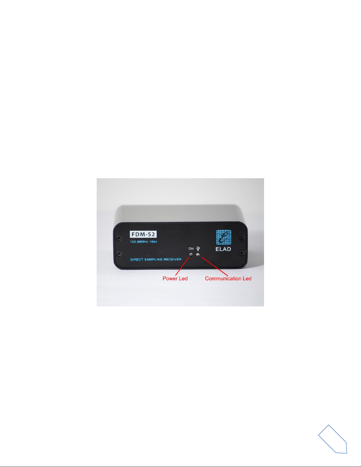
1.2 Front panel description
Power Led : turns on when the receiver is connected to a USB port of the PC and it is switched on.
Communication Led : shows the communication between the receiver and the PC.
© 2021 ELAD S.r.l. All rights reserved. No part of this document may be reproduced, published, used, disclosed or disseminated
in any form or by any means, electronic, photocopying or otherwise, without prior written permission of ELAD S.r.l.
3
Page 4
ELAD FDM-S2 User Manual - Rev 2 - 06/2021
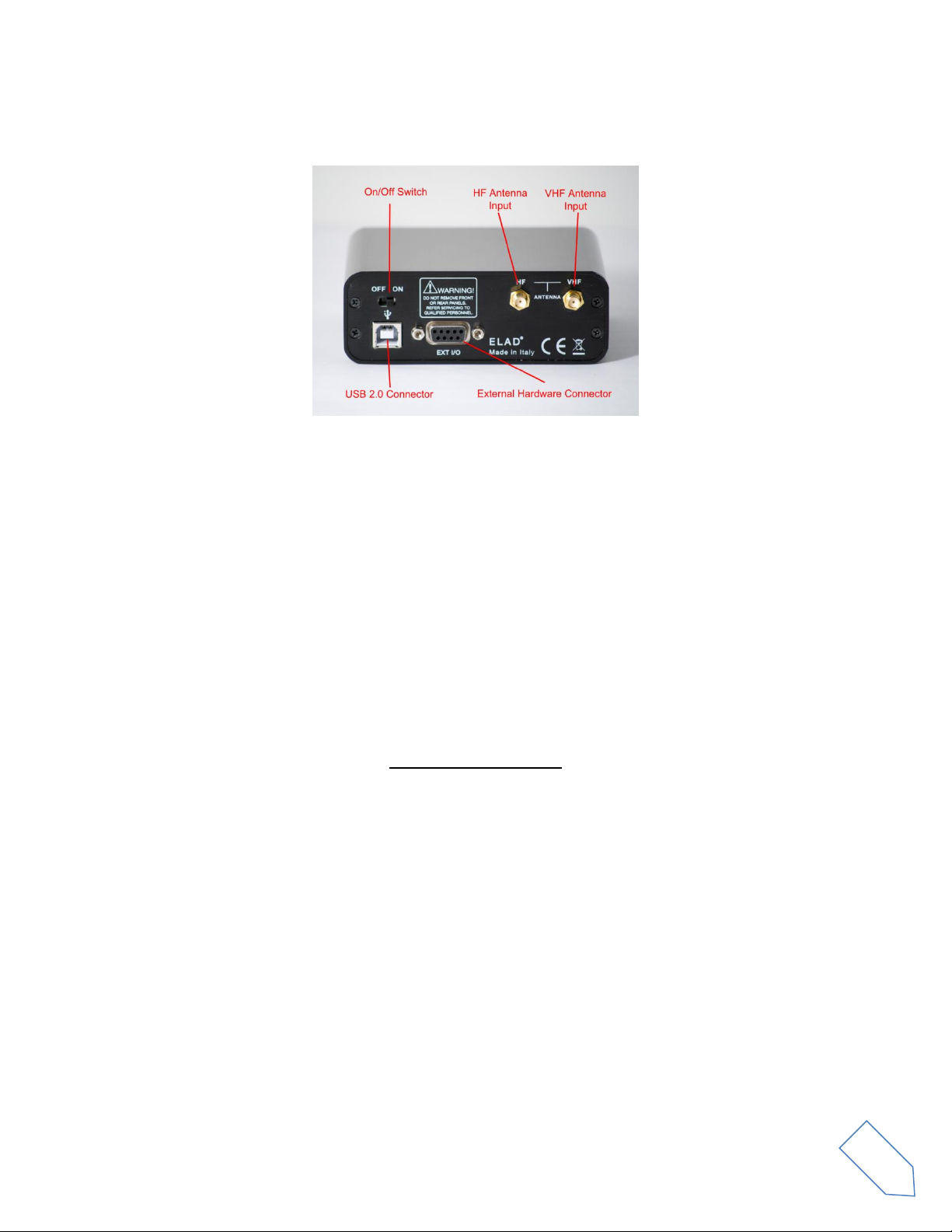
1.3 Rear panel description
USB 2.0 Connector : connection with the PC. Please use the supplied cable.
On/Off Switch : turn On/Off the FDM-S2.
HF Antenna Input : SMA 50Ω input connector for HF band, +20dBm max.
VHF Antenna Input : SMA 50Ω input connector for VHF band, +20dBm max.
External Hardware Connector : DB9 connector for external hardware (e.g. pre-selector filters board).
This is NOT a serial port.
© 2021 ELAD S.r.l. All rights reserved. No part of this document may be reproduced, published, used, disclosed or disseminated
in any form or by any means, electronic, photocopying or otherwise, without prior written permission of ELAD S.r.l.
4
Page 5

ELAD FDM-S2 User Manual - Rev 2 - 06/2021
2 FDM-SW2 Software Installation
2.1 First-time install
Download from the ELAD website http://sdr.eladit.com/FDM-sw2 Software/Current release/ the latest
Complete version. Double-click on the file “setup.exe” inside the folder and follow the instructions.
Windows Installer will first install the prerequisites “Microsoft VC++ 2010 Runtime Libraries” and
“Microsoft .NET Framework 4.0” and then the FDM-SW2 software.
2.2 Update an existing version
Download from the ELAD website http://sdr.eladit.com/FDM-sw2 Software/Current release/ the latest
Only Installer version. Double click on file “ELAD_FDMSW2Setup_v_x.y.msi” included in the update and
follow the instructions.
© 2021 ELAD S.r.l. All rights reserved. No part of this document may be reproduced, published, used, disclosed or disseminated
in any form or by any means, electronic, photocopying or otherwise, without prior written permission of ELAD S.r.l.
5
Page 6
ELAD FDM-S2 User Manual - Rev 2 - 06/2021
3 USB Driver
3.1 First driver installation
To install the USB driver, connect the USB port of the FDM-S2 to a USB port of your computer and power
on the FDM-S2. When Windows detects the new hardware, follow the steps listed below to install the
driver correctly.
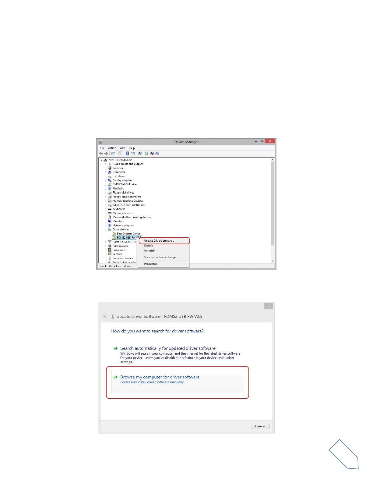
Open the Device Manager, expand Other devices and locate the FDM-S2 node. Select FDM-S2, right
click on it and execute Update Driver Software.
When Windows starts the installation procedure, select the option Browse my computer for driver
software (the second option).
© 2021 ELAD S.r.l. All rights reserved. No part of this document may be reproduced, published, used, disclosed or disseminated
in any form or by any means, electronic, photocopying or otherwise, without prior written permission of ELAD S.r.l.
6
Page 7
ELAD FDM-S2 User Manual - Rev 2 - 06/2021
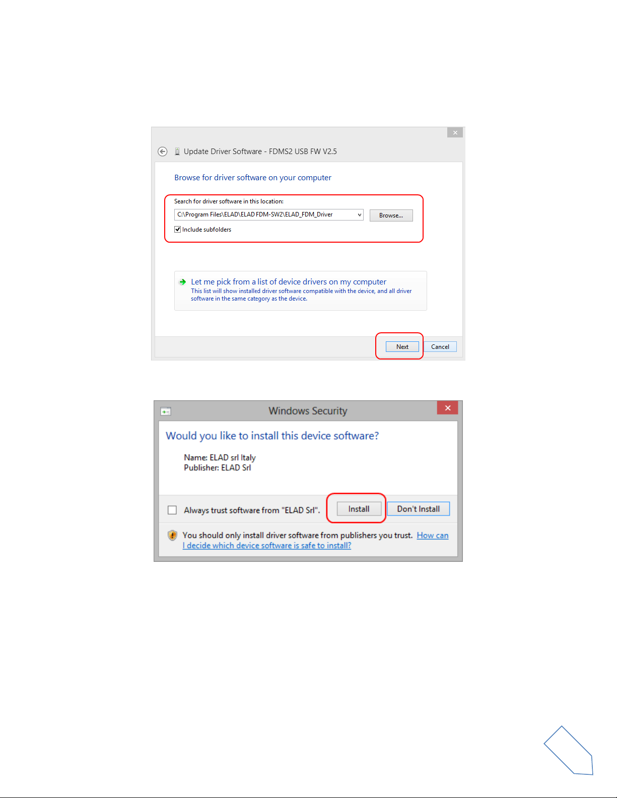
In the next window, insert the driver folder location using the Browse button and check the option
Include subfolders, in this way the manual driver search is enabled. Select the folder: C:\Program Files
(x86)\ ELAD\ELAD FDM-SW2\ELAD_FDM_Driver then click Next.
Click Install.
© 2021 ELAD S.r.l. All rights reserved. No part of this document may be reproduced, published, used, disclosed or disseminated
in any form or by any means, electronic, photocopying or otherwise, without prior written permission of ELAD S.r.l.
7
Page 8

ELAD FDM-S2 User Manual - Rev 2 - 06/2021
Let the hardware installation complete automatically.
At the procedure ending, click on Close, then disconnect and reconnect the FDM-S2 on the same USB
port. Now the USB driver of the FDM-S2 is installed on your computer.
© 2021 ELAD S.r.l. All rights reserved. No part of this document may be reproduced, published, used, disclosed or disseminated
in any form or by any means, electronic, photocopying or otherwise, without prior written permission of ELAD S.r.l.
8
Page 9
ELAD FDM-S2 User Manual - Rev 2 - 06/2021
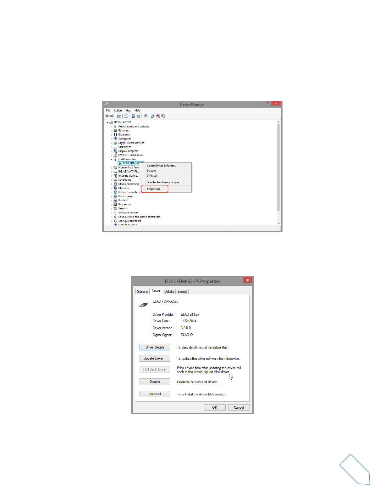
3.2 Driver installation check
To check the driver current version, connect the FDM-S2 to the computer USB port where the driver is
already installed and power on the FDM-S2. Open the Device Manager, expand the ELAD Samplers
node, right click on ELAD FDM-S2 and select Properties.
When the window opens, select the Driver tab. You can read provider name, current driver release date
and current driver version. The picture below gives an example.
© 2021 ELAD S.r.l. All rights reserved. No part of this document may be reproduced, published, used, disclosed or disseminated
in any form or by any means, electronic, photocopying or otherwise, without prior written permission of ELAD S.r.l.
9
Page 10

ELAD FDM-S2 User Manual - Rev 2 - 06/2021
3.3 Manual driver update
To update the driver, connect the FDM-S2 to the computer USB port where the driver is already
installed and power on the FDM-S2. Open the Device Manager, expand the ELAD Samplers node, right
click on ELAD FDM-S2 and execute Update Driver Software.
When Windows starts the installation procedure, select the option Browse my computer for driver
software.
© 2021 ELAD S.r.l. All rights reserved. No part of this document may be reproduced, published, used, disclosed or disseminated
in any form or by any means, electronic, photocopying or otherwise, without prior written permission of ELAD S.r.l.
10
Page 11

ELAD FDM-S2 User Manual - Rev 2 - 06/2021
In the next window, disable the option Include subfolders and choose Let me pick from a list of device
drivers on my computer. Don’t click Next.
Verify that Show compatible hardware option is checked and ELAD FDM-S2 is selected, then click on
Have a Disk. In this way the manual driver update is enabled. Don’t click Next.
Click on Browse and search for the FDM-S2 driver update folder location, then open
winusb_fdmsampler.inf file. Click OK and then Next.
© 2021 ELAD S.r.l. All rights reserved. No part of this document may be reproduced, published, used, disclosed or disseminated
in any form or by any means, electronic, photocopying or otherwise, without prior written permission of ELAD S.r.l.
11
Page 12

ELAD FDM-S2 User Manual - Rev 2 - 06/2021
Let the hardware installation complete automatically, at the procedure ending click on Close, then
disconnect and reconnect the FDM-S2 device on the same USB port.
© 2021 ELAD S.r.l. All rights reserved. No part of this document may be reproduced, published, used, disclosed or disseminated
in any form or by any means, electronic, photocopying or otherwise, without prior written permission of ELAD S.r.l.
12
Page 13
ELAD FDM-S2 User Manual - Rev 2 - 06/2021
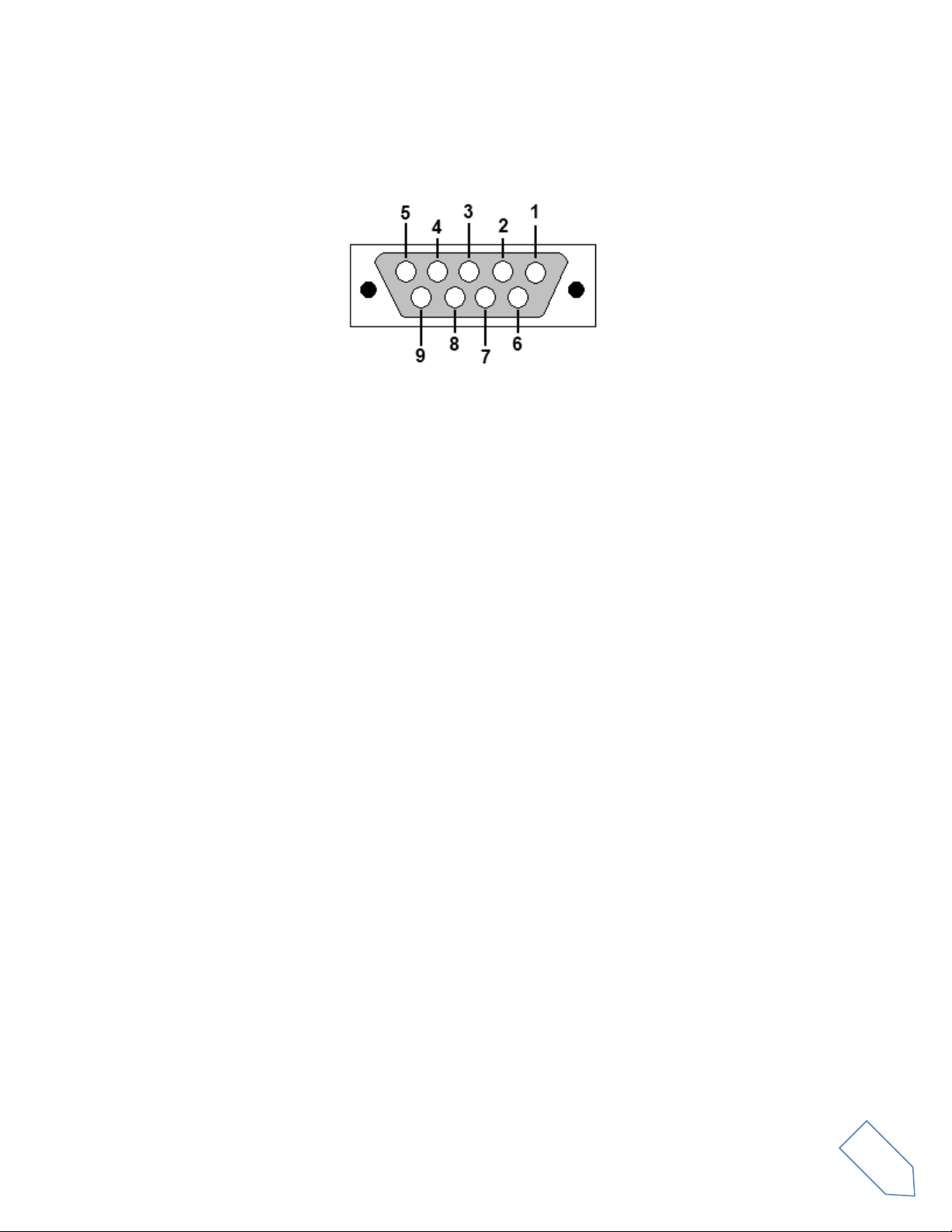
Annex - External Hardware Connector
Pin 1: SFE Latch 595
Pin 2: I2C SCL
Pin 3: SFE CLOCK 595
Pin 4: I2C SDA
Pin 5: Ground
Pin 6: Mute
Pin 7: Reserved
Pin 8: SFE Data 595
Pin 9: Vcc (4.5V)
To mute the FDM-S2, connect the Pin 6 to ground.
Note: the maximum cable length should not exceed 100 mm.
© 2021 ELAD S.r.l. All rights reserved. No part of this document may be reproduced, published, used, disclosed or disseminated
in any form or by any means, electronic, photocopying or otherwise, without prior written permission of ELAD S.r.l.
13
Page 14

ELAD FDM-S2 User Manual - Rev 2 - 06/2021
ELAD FDM-S2
TECHNICAL SPECIFICATIONS
GENERAL
Frequency Coverage
HF+50MHz Band (10 kHz ÷ 54 MHz): Direct Sampling Mode
VHF1 Band (74-108MHz): Undersampling Mode
VHF2 Band (135-148MHz): Undersampling Mode
Bypass for experimenting use
Antenna Connectors
HF+50MHz Band input: SMA (50 Ω) SMA/BNC adapter included
VHF1 & VHF1 Bands input: SMA (50 Ω) SMA/BNC adapter included
Temperature Range
0 ÷ 40 °C
PC Interface
High-Speed USB 2.0 (480 Mbit/s)
Power Supply
USB powered with double USB cable (included)
Power Consumption
Less than 4 W (5 V-750 mA) from USB (double USB cable required)
With slow Sample Rate Dlls (for example 192kSamp/sec) typical 2.6 W
External I/O Connector
Female DB9 (mute control, I2C and SPI interface)
Absolute Maximum
RF Input Level
+20 dBm
Dimensions
110 (W) x 40 (H) x 90 (D) mm
Weight
360 g
HF+50MHz
Band
RECEIVER
Configuration
Direct sampling – ADC DDC with FPGA Xilinx Spartan6 XC6LXC25
A/D Conversion
122.88 MSPS @ 16 bit/sample
Sensitivity
HS
(1)
Typical:
-122 dBm (CW, BW 500 Hz, 10 dB (S+N)/N)
LS
(2)
Typical:
-110 dBm (CW, BW 500 Hz, 10 dB (S+N)/N)
3rd Oder Intercept Point
HS
(1)
Typical:
+23 dBm @ 14 MHz, Spacing 2 kHz
+16 dBm @ 50 MHz, Spacing 2 kHz
LS
(2)
Typical:
+31 dBm @ 14 MHz, Spacing 2 kHz
+25 dBm @ 50 MHz, Spacing 2 kHz
Blocking Gain
Compression
Typical: > 115 dB @ 10 MHz, Spacing 2 kHz, CW, BW 500 Hz
Noise Floor (MDS)
HS
(1)
Typical:
-132 dBm @ 14 MHz, CW, BW 500 Hz, NR
(3)
Off
-138 dBm @ 14 MHz, CW, BW 500 Hz, NR
(3)
On
-130 dBm @ 50 MHz, CW, BW 500 Hz, NR
(3)
Off
-136 dBm @ 50 MHz, CW, BW 500 Hz, NR
(3)
On
LS
(2)
Typical:
-120 dBm @ 14 MHz, CW, BW 500 Hz, NR
(3)
Off
-126 dBm @ 14 MHz, CW, BW 500 Hz, NR
(3)
On
-118 dBm @ 50 MHz, CW, BW 500 Hz, NR
(3)
Off
-124 dBm @ 50 MHz, CW, BW 500 Hz, NR
(3)
On
Clipping Level
HS
(1)
: -8 dBm @ 14 MHz, -12 dBm @ 50 MHz
LS
(2)
: +4 dBm @ 14 MHz, 0 dBm @ 50 MHz
Internal Spurious Carriers
Typical: < -115 dBm @ 384 kSamp/sec, HS
(1)
VHF1
Band
RECEIVER
Configuration
Undersampling – ADC DDC with FPGA Xilinx Spartan6 XC6LXC25
A/D Conversion
122.88 MSPS @ 16 bit/sample
Sensitivity
(WBFM @ 12 dB SINAD)
HS
(1)
Typical: 2.5 µV @ 98 MHz
LS
(2)
Typical: 10 µV @ 98 MHz
3rd Oder Intercept Point
HS
(1)
Typical: +21 dBm @ 98 MHz, Spacing 2 kHz
LS
(2)
Typical: +29 dBm @ 98 MHz, Spacing 2 kHz
Noise Floor (MDS)
HS
(1)
Typical:
-126 dBm @ 98 MHz, CW, BW 500 Hz, NR
(3)
Off
-132 dBm @ 98 MHz, CW, BW 500 Hz, NR
(3)
On
LS
(2)
Typical:
-114 dBm @ 98 MHz, CW, BW 500 Hz, NR
(3)
Off
-120 dBm @ 98 MHz, CW, BW 500 Hz, NR
(3)
On
Clipping Level
HS
(1)
: -3 dBm @ 98 MHz
LS
(2)
: +9 dBm @ 98 MHz
Internal Spurious Carriers
Typical: < -110 dBm @ 384 kSamp/sec, HS
(1)
VHF2
Band
RECEIVER
Configuration
Undersampling – ADC DDC with FPGA Xilinx Spartan6 XC6LXC25
A/D Conversion
122.88 MSPS @ 16 bit/sample
Sensitivity
(FM @ 12 dB SINAD)
Typical:
0.4 µV @ 145 MHz, NR
(3)
Off
0.2 µV @ 145 MHz, NR
(3)
On
3rd Oder Intercept Point
Typical: +5 dBm @ 145 MHz, Spacing 2 kHz
Noise Floor (MDS)
Typical:
-137 dBm @ 145 MHz, CW, BW 500 Hz, NR
(3)
Off
-143 dBm @ 145 MHz, CW, BW 500 Hz, NR
(3)
On
Clipping Level
Typical: -19 dBm @ 145 MHz
Internal Spurious Carriers
Typical: < -100 dBm @ 384 kSamp/sec
FM Band Rejection
> 60 dB
Typical: 75 dB
Measured: 80dB @ 145 MHz, Interferer @ 100.76 MHz
(1)
High Sensitivity Mode,
(2)
Low Sensitivity Mode,
(3)
Noise Reduction
All stated specifications and other product information provided in this document are subject to change without notice or obligation.
Rev. 1
Technical Specifications
© 2021 ELAD S.r.l. All rights reserved. No part of this document may be reproduced, published, used, disclosed or disseminated
in any form or by any means, electronic, photocopying or otherwise, without prior written permission of ELAD S.r.l.
14
Page 15

ELAD FDM-S2 User Manual - Rev 2 - 06/2021
CANEVA
Place
May, 19th 2021
Date
Signature
Declaration of Conformity (EC)
The product marked as
FDM-S2
manufactured by
Manufacturer : ELAD S.r.l.
Address : Via Col De Rust, 11
I-33070 CANEVA (PN)
is produced in conformity to the requirements contained in the following EC directives :
Radio equipment Directive 2014/53/EU
EMC Directive 2014/30/EU
Low Voltage Directive 2014/35/EU
RoHS Directive 2011/65/EU
The product conforms to the following product specifications :
Radio, Emissions & Immunity :
EN 301 489-1 V2.2.3 (2019-11)
EN 301 489-15 V2.2.1 (2019-04)
EN 301 783 V2.1.1 (2016-01)
EN 55032:2015/A11:2020
EN 55035:2017/A11:2020
Safety :
EN 62368-1:2014
and further amendments.
This declaration is under responsibility of the manufacturer
ELAD S.r.l.
Via Col De Rust, 11
I-33070 CANEVA (PN)
Issued by
Name : Franco Milan
Function : President of ELAD S.r.l.
© 2021 ELAD S.r.l. All rights reserved. No part of this document may be reproduced, published, used, disclosed or disseminated
in any form or by any means, electronic, photocopying or otherwise, without prior written permission of ELAD S.r.l.
15
Page 16

ELAD FDM-S2 User Manual - Rev 2 - 06/2021
Declaration of Conformity (FCC)
The product marked as
FDM-S2
manufactured by
Manufacturer : ELAD S.r.l.
Address : Via Col De Rust, 11
I-33070 CANEVA (PN)
complies with the following requirements :
- FCC (Federal Communications Commission) Part 15.
Operation is subject to the following two conditions :
(1) this device may not cause harmful interference,
(2) this device must accept any interference received, including interference that may cause undesired operation.
NOTE : this equipment has been tested and found to comply with the limits for a Class B digital device, pursuant to
Part 15 of the FCC Rules. These limits are designed to provide reasonable protection against harmful interference
in a residential installation. This equipment generates, uses and can radiate radio frequency energy and, if not
installed and used in accordance with the instructions, may cause harmful interference to radio communications.
However, there is no guarantee that interference will not occur in a particular installation. If this equipment does
cause harmful interference to radio or television reception, which can be determined by turning the equipment off
and on, the user is encouraged to try to correct the interference by one or more of the following measures:
reorient or relocate the receiving antenna,
increase the separation between the equipment and receiver,
connect the equipment into an outlet on a circuit different from that to which the receiver is connected,
consult the dealer or an experienced radio/TV technician for help.
Changes or modification not expressly approved by the party responsible for compliance could void the user’s
authority to operate the equipment.
FCC ID : 2AAE5FDM-S2
This product is distributed in USA by :
ELAD USA Inc.
618 Cummings Chapel Road
Ridgeville, SC 29472. USA
USA Sales Email : Sales@elad-usa.com
USA Support Email : Support@elad-usa.com
Phone : 312-320-8160
© 2021 ELAD S.r.l. All rights reserved. No part of this document may be reproduced, published, used, disclosed or disseminated
in any form or by any means, electronic, photocopying or otherwise, without prior written permission of ELAD S.r.l.
16
 Loading...