

Page 1

technical and operational documentation
Doc. version: 3.0.100
Page 2

Contents
1.
2.
3.
3.1.
3.2.
4.
4.1.
4.2.
4.3.
4.4.
5.
6.
6.1.
6.2.
6.3.
6.4.
6.5.
6.6.
6.7.
6.8.
APPLICATION OF THE FPM+ UNIT ..................................................................................................... 4
FPM+ ARCHITECTURE AND TOPOLOGY ............................................................................................. 5
REQUIREMENTS FOR EXTERNAL COMPONENTS .............................................................................. 7
FPM+ power supply .......................................................................................................................................................................... 7
Electrical installation ......................................................................................................................................................................... 7
FPM+ LIMITATIONS ........................................................................................................................... 8
No. of items per bus .......................................................................................................................................................................... 8
Length of bus between modules .................................................................................................................................................... 8
Length of MP-Bus .............................................................................................................................................................................. 8
Number of zones ............................................................................................................................................................................... 8
FPM+ UNIT AND MODULE SPECIFICATIONS ..................................................................................... 9
FPM+ MODULES .............................................................................................................................. 15
FPM+ control unit - central (MASTER) module ......................................................................................................................... 15
LSK ..................................................................................................................................................................................................... 17
e.LSK .................................................................................................................................................................................................. 18
EPSCUS ............................................................................................................................................................................................. 19
e.USP..................................................................................................................................................................................................20
SKC .....................................................................................................................................................................................................20
SKC-A ................................................................................................................................................................................................. 21
FPM+ bus repeater module ........................................................................................................................................................... 22
7.
7.1.
7.2.
7.3.
7.4.
7.5.
7.6.
7.7.
8.
8.1.
8.2.
8.3.
8.4.
8.5.
8.6.
8.7.
8.8.
9.
9.1.
9.2.
9.3.
10.
10.1.
10.2.
10.3.
10.4.
10.5.
10.6.
10.7.
10.8.
10.9.
CONNECTING MODULES .................................................................................................................. 24
FPM-X-YY-ZZ housings .................................................................................................................................................................. 24
EPSCUS ............................................................................................................................................................................................. 25
e.UPS.................................................................................................................................................................................................. 25
LSK ..................................................................................................................................................................................................... 26
e.LSK .................................................................................................................................................................................................. 29
SKC-A ................................................................................................................................................................................................. 29
FPM+ bus repeater .......................................................................................................................................................................... 32
MAIN HOUSINGS FOR CONTROL UNIT MODULES ........................................................................... 33
EPSCUS ............................................................................................................................................................................................. 33
LSK ..................................................................................................................................................................................................... 33
SKC ..................................................................................................................................................................................................... 33
SKC-A ................................................................................................................................................................................................. 34
Main housing of the control unit, type FPM-M-YY-ZZ .............................................................................................................. 34
FPM-X-YY-ZZ .................................................................................................................................................................................... 35
FPM-U-x-x-x-x-x and FPM-L-x-x-x-x-x ........................................................................................................................................... 36
Plastic multiple-module housings ................................................................................................................................................ 36
ASSEMBLY INSTRUCTIONS ............................................................................................................. 40
Bus......................................................................................................................................................................................................40
Shielding ............................................................................................................................................................................................40
External power supplies .................................................................................................................................................................40
TYPES OF INPUTS IN THE UNIT ....................................................................................................... 40
Input type: unused ........................................................................................................................................................................... 41
Input type: digital NO ...................................................................................................................................................................... 41
Input type: digital NC....................................................................................................................................................................... 41
Input type: digital three-state ........................................................................................................................................................ 42
Input type: analog resistive ........................................................................................................................................................... 42
Input type: digital supervised NO ................................................................................................................................................. 42
Input type: digital supervised NC .................................................................................................................................................. 42
Input type: analog 0-5V .................................................................................................................................................................. 43
Input type: analog 4-20mA ............................................................................................................................................................ 43
Page 3

11.
TYPES OF OUTPUTS IN THE UNIT ................................................................................................... 44
11.1.
Output type: relay ............................................................................................................................................................................ 44
11.2.
Output type: Open Collector .......................................................................................................................................................... 44
11.3.
Output type: actuators and appliances compatible with MP-Bus standard ........................................................................ 44
12.
INPUT FUNCTIONS .......................................................................................................................... 45
12.1.
Input function: disabled .................................................................................................................................................................. 45
12.2.
Input function: fire alarm ................................................................................................................................................................ 45
12.3.
Input function: smoke alarm in a duct ........................................................................................................................................ 45
12.4.
Input function: smoke alarm in air intake ................................................................................................................................... 45
12.5.
Input function: smoke warning in air intake ............................................................................................................................... 45
12.6.
Input function: smoke warning in a duct .................................................................................................................................... 45
12.7.
Input function: fire reset ................................................................................................................................................................. 45
12.8.
Input function: firefighting action ................................................................................................................................................. 45
12.9.
Input function: technical alarm ..................................................................................................................................................... 45
12.10. Input function: ventilation .............................................................................................................................................................. 45
12.11. Input function: forced air supply from downstairs ................................................................................................................... 45
12.12. Input function: forced air supply from upstairs ......................................................................................................................... 45
12.13. Input function: indicator light test ................................................................................................................................................ 45
12.14. Input function: measurement ....................................................................................................................................................... 45
12.15. Input function: venting open ......................................................................................................................................................... 45
12.16. Input function: venting close ......................................................................................................................................................... 46
12.17. Input function: drive start test....................................................................................................................................................... 46
12.18. Input function: power failure ......................................................................................................................................................... 46
12.19. Input function: limit switch ............................................................................................................................................................ 46
12.20. Input function: limit switch group ................................................................................................................................................ 46
12.21. Input function: manual control ..................................................................................................................................................... 46
12.22. Input function: manual fire alarm ................................................................................................................................................. 46
12.23. Input function: smoke detector alarm ......................................................................................................................................... 46
12.24. Input function: smoke detector warning ..................................................................................................................................... 46
12.25. Input function: evacuation with firefighting action ................................................................................................................... 46
12.26. Input function: general alarm ........................................................................................................................................................ 46
12.27. Input function: pressure control ................................................................................................................................................... 46
12.28. Input function: external temperature sensor ............................................................................................................................. 46
12.29. Input function: internal temperature sensor .............................................................................................................................. 47
12.30. Input function: upper pressure sensor ........................................................................................................................................ 47
12.31. Input function: bottom temperature sensor............................................................................................................................... 47
13.
OUTPUT FUNCTIONS ....................................................................................................................... 48
13.1.
Output function: normal fan switch on ....................................................................................................................................... 48
13.2.
Output function: reverse fan switch on ....................................................................................................................................... 48
13.3.
Output function: upper fan rotation direction ............................................................................................................................ 48
13.4.
Output function: lower fan rotation direction ............................................................................................................................. 48
13.5.
Output function: fan switch on with firefighting action ........................................................................................................... 48
13.6.
Output function: evacuation with firefighting action ................................................................................................................ 48
13.7.
Output function: sensor power supply reset .............................................................................................................................. 48
13.8.
Output function: indicator lights ................................................................................................................................................... 48
13.9.
Output function: fire alarm............................................................................................................................................................. 48
13.10. Output function: technical alarm .................................................................................................................................................. 48
13.11. Output function: line actuator plus .............................................................................................................................................. 48
13.12. Output function: line actuator minus ........................................................................................................................................... 48
13.13. Output function: failure ................................................................................................................................................................... 48
13.14. Output function: actuator .............................................................................................................................................................. 48
13.15. Output function: actuator disabled .............................................................................................................................................. 48
13.16. Output function: cut-off gate ......................................................................................................................................................... 49
13.17. Input function: pressure regulator ............................................................................................................................................... 49
13.18. Output function: exhaust bottom ................................................................................................................................................. 49
13.19. Output function: exhaust top ........................................................................................................................................................ 49
13.20. Output function: supply bottom ................................................................................................................................................... 49
13.21. Output function: supply top ........................................................................................................................................................... 49
14.
COMMISSIONING INSTRUCTIONS ................................................................................................... 50
Page 4

15.
15.1.
15.2.
15.3.
16.
16.1.
16.2.
16.3.
17.
PRODUCT SAFETY PRECAUTIONS .................................................................................................. 51
Proper usage regulations ............................................................................................................................................................... 51
Periodical inspection and maintenance regulations ................................................................................................................ 51
Safety precautions .......................................................................................................................................................................... 51
PACKAGING, TRANSPORT AND STORAGE ....................................................................................... 53
Packaging ......................................................................................................................................................................................... 53
Transport regulations ..................................................................................................................................................................... 53
Storage regulations ......................................................................................................................................................................... 53
ENVIRONMENT IMPACT .................................................................................................................. 54
LIST OF DRAWINGS ....................................................................................................................................... 55
18.
APPENDIX A: FPM-X-YY-ZZ HOUSING SPECIFICATIONS ................................................................. 56
19.
APPENDIX B : - DRAWINGS OF FPM-X-YY-ZZ HOUSINGS ............................................................... 57
19.1.
FPM-2-YY-ZZ .................................................................................................................................................................................... 57
19.2.
FPM—4-YY-ZZ .................................................................................................................................................................................. 59
19.3.
FPM-6-YY-ZZ .................................................................................................................................................................................... 61
19.4.
FPM-8-YY-ZZ .................................................................................................................................................................................... 63
19.5.
FPM-10-YY-ZZ .................................................................................................................................................................................. 65
20.
APPENDIX C : FPM-U-X-X-X-X-X AND FPM-L-X-X-X-X HOUSING SPECIFICATIONS ......................... 67
21.
APPENDIX D : FPM-U-X-X-X-X-X AND FPM-L-X-X-X-X HOUSINGS - DRAWINGS .............................. 68
21.1.
FPM-U-4-6-0-A-D .............................................................................................................................................................................. 68
21.2.
FPM-U-4-6-18-A-G ........................................................................................................................................................................... 69
21.3.
FPM-U-4-6-0-B-D .............................................................................................................................................................................. 69
21.4.
FPM-U-4-6-18-B-G ...........................................................................................................................................................................70
21.5.
FPM-U-6-6-0-A-D ..............................................................................................................................................................................70
21.6.
FPM-U-6-6-26-A-G ........................................................................................................................................................................... 71
21.7.
FPM-U-6-6-0-B-D .............................................................................................................................................................................. 71
21.8.
FPM-U-6-6-26-B-G ........................................................................................................................................................................... 72
21.9.
FPM-L-8-6-0-A-D .............................................................................................................................................................................. 72
21.10. FPM-L-8-6-18-A-G ............................................................................................................................................................................ 73
21.11. FPM-L-8-6-0-B-D .............................................................................................................................................................................. 73
21.12. FPM-L-8-6-18-B-G ............................................................................................................................................................................ 74
22.
APPENDIX E: CUSTOM HOUSINGS .................................................................................................. 75
Page 5
1. APPLICATION OF THE FPM+ UNIT
The FPM Plus fire alarm control panel is a modular device
for monitoring the operating status and control of all the
pieces of equipment triggered as a result or during a fire.
These can be dedicated firefighting systems, such as:
Fire emergency ventilation system,
Fire shutdown systems,
Evacuation support system,
Other building systems triggered to do any action as a result
of fire.
Other systems include:
Access control system,
Burglary and robbery alarm system,
Escalator,
Lifts,
Utilities control (shut-off) systems,
Heat pumps and HVAC systems.
The unit features integration of various types of systems
(with different functions) and building a single control
algorithm (control matrix).
9) (…) equipment (fixed or semi-fixed, actuated manually or
automatically) having the function of prevention, detection
and putting out or containment of fires, particularly fixed or
semi-fixed fire extinguishing and fire protection systems,
Page 4 of 78
inerting systems, voice alarm system and fire alarm system
equipment, including alerting/alarm devices, fire alarm
receiving equipment, damage alert receiving system,
evacuation lighting systems, internal standpipes and
standpipe valves, external standpipes, pumps in fire water
pumping stations, fire dampers, smoke extraction
equipment, explosion prevention and containment
equipment, smoke curtains and doors, fire doors and other
fire rated closures if fitted with control systems, fire
emergency power shutdown devices, and hoists for rescue
teams;
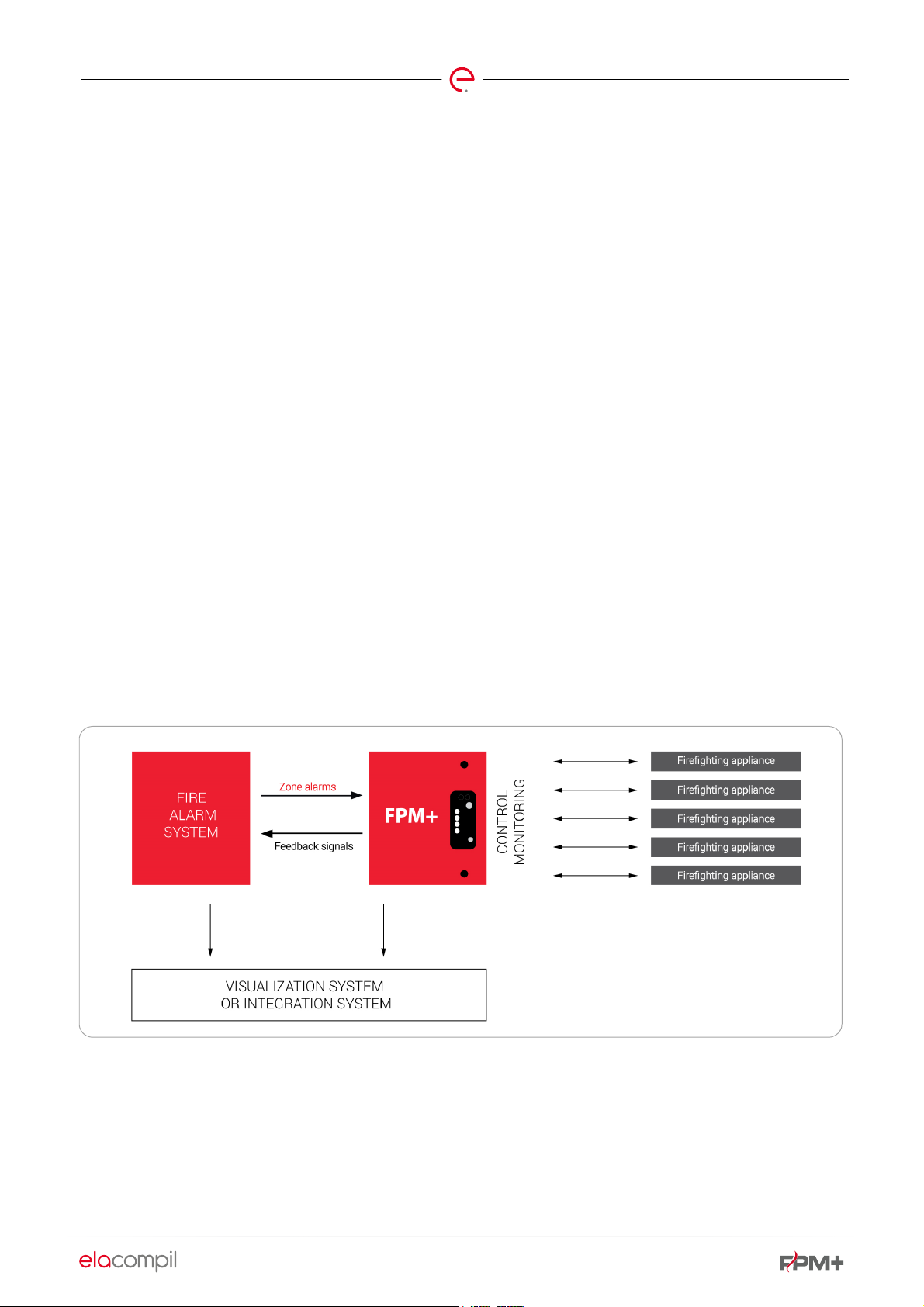
The control unit is responsible for technical handling of fire
controls in the building. In response to an alarm from the Fire
Alarm System, the unit will control all the firefighting
equipment according to the assumed fire scenario.
As a minimum, the link between the Fire Alarm System and
the Control Unit can consist of:
Zone alarms (‘Fire in a zone’) - number of signals equals the
number of zones - signal from FAS to the FPM+control unit,
Feedback alarms - these should be matched to the needs of
the building. Feedback alarms may include notifications of
the control unit operation in fire mode (trigger confirmation),
notifications of damage to the FAS, indications of alarms and
hazards discovered by the control unit (if needed)
Fig. 1 Location of the control unit within the overall fire safety system in the building
Page 6

2. FPM+ ARCHITECTURE AND TOPOLOGY
Page 5 of 78
The FPM+ unit has a modular design and is composed of
modules of various types with various functions. Specific
modules may be enclosed in separate single-module
housings or in group housings where more than one module
can be placed in each.
All the modules are connected with a bus loop. Every module
on the bus is addressable. Information is exchanged digitally
between the modules.
The MASTER module is unique among all the unit modules.
This is the main module of the unit, with the function of
overseeing the exchange of information between the other
modules and the exchange of information between the
control unit and the higher level system (BMS, firefighting
equipment integration system). The MASTER module with
additional control unit handling items (buttons and indicator
lights) is always housed in a separate housing (main
housing of the control unit). Together with the MASTER, this
housing can accommodate the power supply and a
maximum of two EPSCUS controllers.
Other modules can be housed in ABS housings or steel
housings.
Page 7
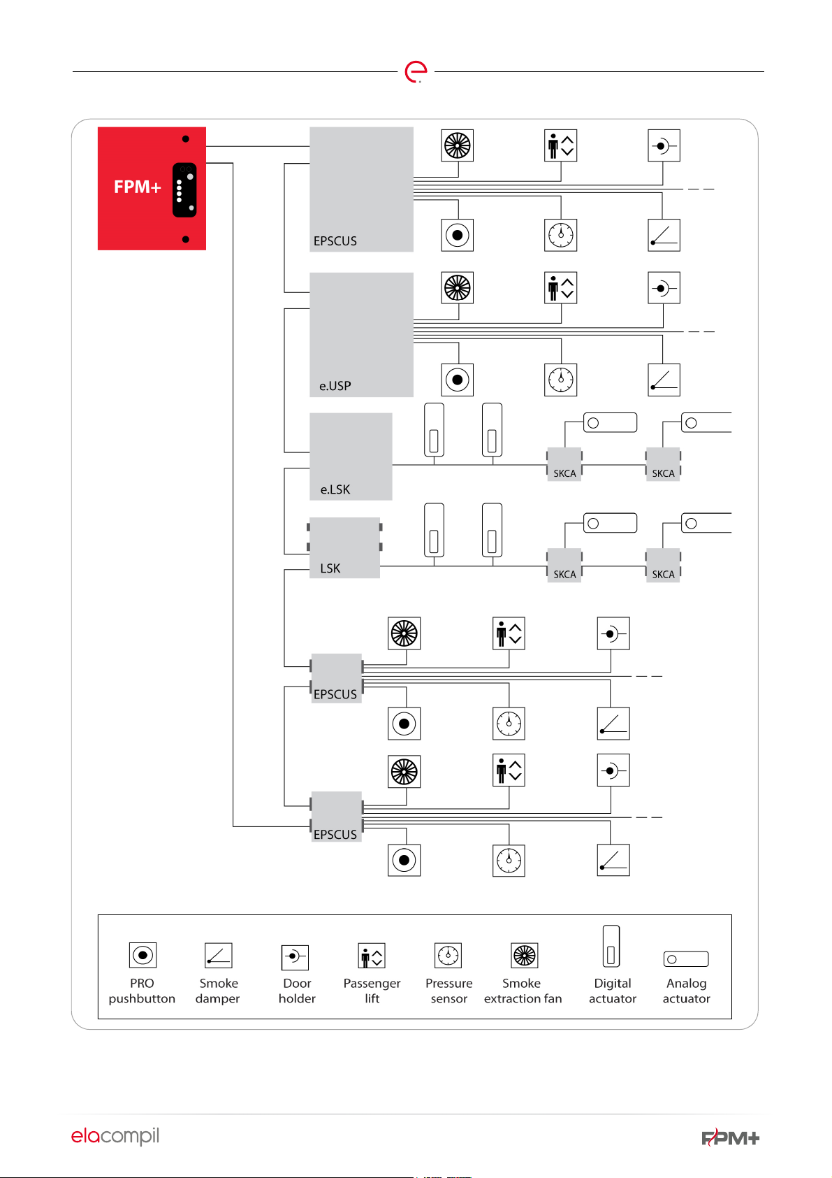
Page 6 of 78
Fig. 2 Control unit topology diagram
Page 8

3. REQUIREMENTS FOR EXTERNAL COMPONENTS
3.1. FPM+ POWER SUPPLY
Page 7 of 78
The FPM+ modules, according to type, can be powered from:
The control unit internal power supply,
External power supply,
Mains power ~230V.
Mains power can only be used when the unit performs
control and monitoring functions over systems which are
not required to work during a fire. An example system of this
type can be a fire damper control system. In this case, mains
3.2. ELECTRICAL INSTALLATION
Electrical installation should be built with flame retardant or
non-flammable cables. The choice of cable depends on the
use of the FPM+ unit in the building. If the FPM+ controls
any equipment or systems which are required to operate
during a fire, a non-flammable cable must be used. If the
FPM+ controls any equipment or systems which are not
required to operate during a fire, a flame retardant cable can
be used.
The general rule is that if at least one system or one
appliance connected to the FPM+ must be operating during
a fire, FPM+ action at the time of fire must be assured.
Therefore, the bus and controller power supply installations
must be wired in non-flammable cables. Connections to
appliances and systems should be wired with a cable
adequate for the requirements prevailing in the building.
For fire safety applications, Certificates of Approval should
be issued for the cables by CNBOP-PIB Scientific and
Research Center for Fire Protection National Research
Institute.
voltage or secure voltage from external power supply units
can be used.
If the FPM+ is expected to monitor and control equipment
and systems which are required to operate during a fire, all
the FPM+ modules should be powered with a buffered
power supply, certified for conformity with EN-PN 54-4 or
EN-PN12101-10, with the supply voltage and output current
appropriate for the specific application.
Cable ways for fire safety applications should be produced
to appropriate rating, i.e. E30/E60/E90, etc. For a specific
application. Conformity with the classification requirements
should be verified by an appropriate certificate.
Example cables:
YnTKSYekw 1x2x0.8 – fire retardant cable for wiring
installations not required to operate during a fire. Can be
used for example to wire a bus linking the modules, or to wire
an MP-Bus.
HTKSHekw PH90 1x2x1 – fire resistant cable for wiring
installations required to operate during a fire. Can be used for
example to connect bus lines.
HDGs 2x1 – fire resistant cable for power supply and control
of systems which need to be powered with electricity during
a fire.
The designer should always make sure that the cable they
intend to use has the requisite approvals and certificates
required by law.
Page 9

4. FPM+ LIMITATIONS
Page 8 of 78
4.1. NO. OF ITEMS PER BUS
In terms of technical feasibility, a maximum of 254
controllers can be covered within a single bus. These
modules are divided into two groups:
126 x LSK / e.LSK controllers
126 x EPSCUS/e.USP controllers
LSK/e.LSK modules have an address pool attributed on
bus 1..126, while the pool attributed to EPSCUS/e.UPS
modules is 129…254.
LSK controllers can be addressed on the basis of settings
of controls on the front panel of the respective module, or
on the basis of controller serial numbers.
EPSCUS, e.USP and e.LSK controllers are addressed on the
basis of controller serial numbers.
4.2. LENGTH OF BUS BETWEEN
MODULES
The bus is divided into sections. Each module on the bus
is the end and the start of the respective sections to which
it is connected. The length of sections between specific
modules should not exceed 1200 meters.
4.3. LENGTH OF MP-BUS
The overall length of a single MP-Bus (connecting 8
actuators with a single LSK module) should not exceed
600 meters.
4.4. NUMBER OF ZONES
Notwithstanding the number of all zones (fire, control,
smoke extraction zones) that can be covered by the FPM+
unit, there is a limitation of the number of zones to which
a specific output can be assigned. This number is limited
to 70 in the software. Should outputs (EPSCUS and e.USP
relay outputs and LSK and e.LSK actuators) need to be
assigned to a higher number of zones, contact the FPM+
unit manufacturer.
Page 10

5. FPM+ UNIT AND MODULE SPECIFICATIONS
Table 1 FPM+ unit and module specifications
GENERAL DESCRIPTION
Page 9 of 78
FPM+ architecture
Climate class
Loops
Minimum no. of modules
Maximum no. of modules
Max. bus voltage
Max. bus current
IP
Operating temperature range
Dimensions (L x W x H)
Firmware version
Manual/auto options
Systems and appliances integrated
with the control unit
Modular, loop, addressable unit
2
1x
1x, as per 3.1.1 of this approval
1 MASTER
126 EPSCUS/e.USP
126 LSK or LSK/24 or e.LSK
2016 SKC, SKC-A (using 126 e.LSK), or 1008 SKC, SKC-A (using 126 LSK)
A MASTER module is required for more than 1 module
5VDC
Short-circuit current 50mA (limited with a polyfuse)
IP42 for external housing of the control unit and individual housings
IP55 for SKC modules
IP65 for LSK and LSK/24 modules
-50C to +550C (relative humidity 80% at 550C)
Min. 500x600x250
Other dimensions as per the control unit documentation
FPMplus
Automatic, through a signal from the fire alarm system control panel, smoke
extraction system control panel, or automatic smoke detectors of the fire
alarm system.
Manual trigger with the smoke extraction button
Manual control from the integrating system
Fire alarm control panels
Smoke and heat propagation control system components (shut-off dampers,
smoke vents, fire vents, smoke curtains, etc.)
Conventional fire detectors (readings on parametric lines)
Smoke extraction buttons and manual call points
Pressure sensors
Temperature sensors
Wind direction and wind force detectors
Voltage presence detectors
Fire dampers
Electromagnetic holders (releases)
Voice alarm systems
Fixed fire extinguishing equipment
Emergency exit controls
Other building control systems
Intermediary devices, such as: contacts, inverters, switches
Page 11

Other external appliances and systems that may or must be controlled during
a fire, where the design and operating mode makes them integrable with the
control unit
Other systems and appliances without firefighting functions where the
design and operating mode makes them integrable with the control unit
POWER SUPPLY DESCRIPTION
Page 10 of 78
Power supply
Supply voltage
Max. power consumption
Internal operating voltage
Power supply type or other
identification
Operating temperature range
Housing protection grade
Dimensions (L x W x H)
Main power supply: supply voltage
Max. power consumption from
mains
Max. continuous load on power
supply
Max. short-term load on power
supply
Ripples
Uninterrupted power supply: battery
type
Max. battery capacity
Battery charging voltage in buffer
mode
Max. battery charging current
Battery cut-off voltage
Max. resistance of battery bank
circuit
Output circuits: power supply output
voltage range
Functional class
External power supply conforming to PN-EN12101-10 and PN-EN 54-4
Dedicated control unit power supply, type CAMELEON, series ZM24VxxA-
yyyPZ(C), specifically
ZM24V6A-151PZ(C), ZM24V8A-200PZ(C) ZM24V12A-300PZ(C), ZM24V16A-
400PZ(C) and ZM24V24A-600PZ(C)
~230V mains for LSK module
24-48VDC from external power supply
For LSK module powered from ~230VAC mains
2A @ 24VDC (excluding power supply to appliances, such as actuator,
holders, etc.)
24-48VDC
CAMELEON
ZM24V24A-600PZ(C)
-25..70°C
n.a. (installed in multiple-module IP42 housing)
262x111x66mm
With connections 279x111x66mm
184..230..253VAC
230 V AC (-20% / +10%)
2.1A
I
=18A
maxA
I
=24A
maxB
150mV
AGM type (VRLA) lead acid batteries
120Ah
26.4…..28.8V
6A
<21.0V
100mΩ
21.0…28.8V
A
Page 12

Page 11 of 78
Environmental class
2 (when installed in the control unit in IP42 housing)
OUTPUTS DESCRIPTION
Potential-free relay outputs
Potential-free relay contacts
Contact type: changeover
Current capacity: 2A for 30VDC
Resistance of contacts: < 50mΩ
For loads with higher current or voltage, use additional high current relays
Number of zones assignable to a single output: 70
OC outputs
OC type outputs
Max. external voltage 48VDC
Current capacity: 100mA per output at 25°C
Induction load operation only with idling diode!
MP-Bus outputs
MP-Bus output
No. of items on bus: 8
Operating voltage >20VDC
Maximum current >10mA
Maximum outputs
MP-Bus: 126*8 = 1008 x MP-Bus devices for LSK, 2016 for e.LSK
Relay outputs: 1008
O/C: 756
INPUTS DESCRIPTION
Digital inputs
Digital inputs, supervised, with the option of switching off supervision (NO,
NC mode)
Typical line resistance values
Supervision state 1kΩ
Alarm state 3,3kΩ
Analog inputs
Analog inputs for signal acquisition:
4..20mA (with external resistor)
0..5V direct
0..10V with external resistor
Max. inputs
Digital, monitored: 504
Digital/analog (configurable): 1008 for EPSCUS, 2016 for e.LSK
Recommended cable types
For control unit bus: non-flammable cables (for fire ventilation systems and
smoke extraction systems) or flame retardant cables (for fire damper
control), single pair, shielded. Min. core section 0.5mm
Sample cables:
Flame retardant YnTKSYekw 1x2x0.8
Fire resistant HTKSHekw 1x2x1.0 PH90
If the control unit covers at least one appliance requiring uninterrupted power
supply during a fire alarm, fire resistant cables should be used to produce the
bus, in accordance with the applicable legal requirements, including § 187 of
Regulation of the Minister of Infrastructure of 12 April 2002 concerning
Page 13

Supply voltage
IP
No. of inputs
No. of outputs
FPM+ bus
Configuration/visualization bus
Page 12 of 78
technical requirements applicable to buildings and their locations (Journal of
Laws No. 75, item 690, as amended).
For powering actuators - cables should be selected in accordance with the
legal requirements, including § 187 of Regulation of the Minister of
Infrastructure of 12 April 2002 concerning technical requirements applicable
to buildings and their locations (Journal of Laws No. 75, item 690, as
amended).
E.g. fire resistant cable HDGs 2x1
Use of a flame retardant cable, e.g. YnTKSYekw 3x2x0.8, is permitted for
powering and controlling appliances for which uninterrupted power supply is
not required during a fire (e.g. fire cut-off dampers with springreturn
actuator).
If the appliances connected to the control unit require the use of cabling with
varying flammability classifications, use highest rated cables out of the
applicable requirements to build the bus.
Cables must be provided with relevant approval documents for use in fire
protection installations (Certificate of conformity, Certificate of Approval by
CNBOP-PIB Scientific and Research Center for Fire Protection National
Research Institute).
24-48VDC
n.a. (installed in multiple-module IP42 housing)
Digital/analog inputs: 8
Relay outputs: 8
2xRS485
Ethernet
EPSCUS module DESCRIPTION
Supply voltage
IP
24-48VDC
n.a. (installed in multiple-module IP42 housing)
IP42 – for individual housing with ABS
No. of inputs
No. of outputs
Digital/analog inputs: 8
Relay outputs: 8
O/C outputs: 6
FPM+ bus
2xRS485
LSK and LSK/ MODULE DESCRIPTION
Supply voltage
24 - 48VDC for LSK/24
230VAC for LSK
IP
No. of inputs
No. of outputs
FPM+ bus
IP65
Digital inputs: 4
MP-Bus: 1
2xRS485
Page 14

FPM+ BUS REPEATER MODULE DESCRIPTION
Page 13 of 78
Supply voltage
IP
No. of inputs
24VDC
n.a. (installed in multiple-module IP42 housing)
2x RS485
SKC module DESCRIPTION
Supply voltage
IP
No. of inputs
No. of outputs
230VAC
IP55
n/a (power supply module)
24VAC power supply output
SKC-A MODULE
Supply voltage
IP
No. of inputs
230VAC or 24VAC or 24VDC
IP42
MP-Bus: 1
Analog actuator limit switches: 1
No. of outputs
230VAC or 24VDC control output
MP-Bus: 1
e.LSK MODULE DESCRIPTION
Supply voltage
IP
24-48VDC/VAC
IP 20 for the module itself
IP 42 for steel housings (module installed in FPM+ multiple-module housing)
IP 42 for ABS housings (module installed in same housing as SKC-A)
Maximum power consumption
In/out lines
2.4W @ 24VDC
System bus – 2x – EIA-485 (RS-485) standard, galvanically isolated
MP-BUS – 2 x – MP-BUS standard
System bus voltage
Max. bus current in supervised state
Dimensions
+/-5VDC
50mA (typical 0.05mA)
88 x 108 x 62 mm
In ABS housing: 172 x 132 x 78 mm
Weight
ca. 180 g
In ABS housing: 450 g
e.USP MODULE DESCRIPTION
Supply voltage
24-48VDC/VAC
Page 15

Page 14 of 78
IP
Maximum power consumption
In/out lines
System bus voltage
Max. bus current in supervised state
Dimensions
Weight
IP 20 for the module itself
IP 42 for steel housings (module installed in FPM+ multiple-module housing)
IP 42 for ABS housings (module installed in same housing as EPSCUS)
2.4W @ 24VDC
System bus – 2x – EIA-485 (RS-485) standard, galvanically isolated
Inputs – 16 x
Outputs – 8 x - relays
+/-5VDC
50mA (typical 0.05mA)
214 x 108 x 62 mm
In ABS housing: 252 x 202 x 90 mm
ca. 400 g
In ABS housing: 1100 g
Page 16
6. FPM+ MODULES
Page 15 of 78
The FPM Plus system is composed of multiple units (the
central module and local modules) with different functions.
The central module monitors the service of local controllers
Modules are set up in FPM+ Configurator.
and facilitates communication between them.
6.1. FPM+ CONTROL UNIT - CENTRAL (MASTER) MODULE
The master module of FPM+ control unit has the following
functions:
exchange of information between other modules
monitoring loop continuity
connection of FPM+ unit with a visualization system (BMS,
SMS).
Fitted with Ethernet port, two RS485 ports, an RS232 port,
eight relay outputs, and eight inputs.
The communication ports as well as two 5A@VDC relays are
installed on the main board of the module, while the inputs
and the six additional 1A@30VDC outputs are located on the
extension board.
Module inputs are used to monitor and control the unit
(managing lights, buttons, access key).
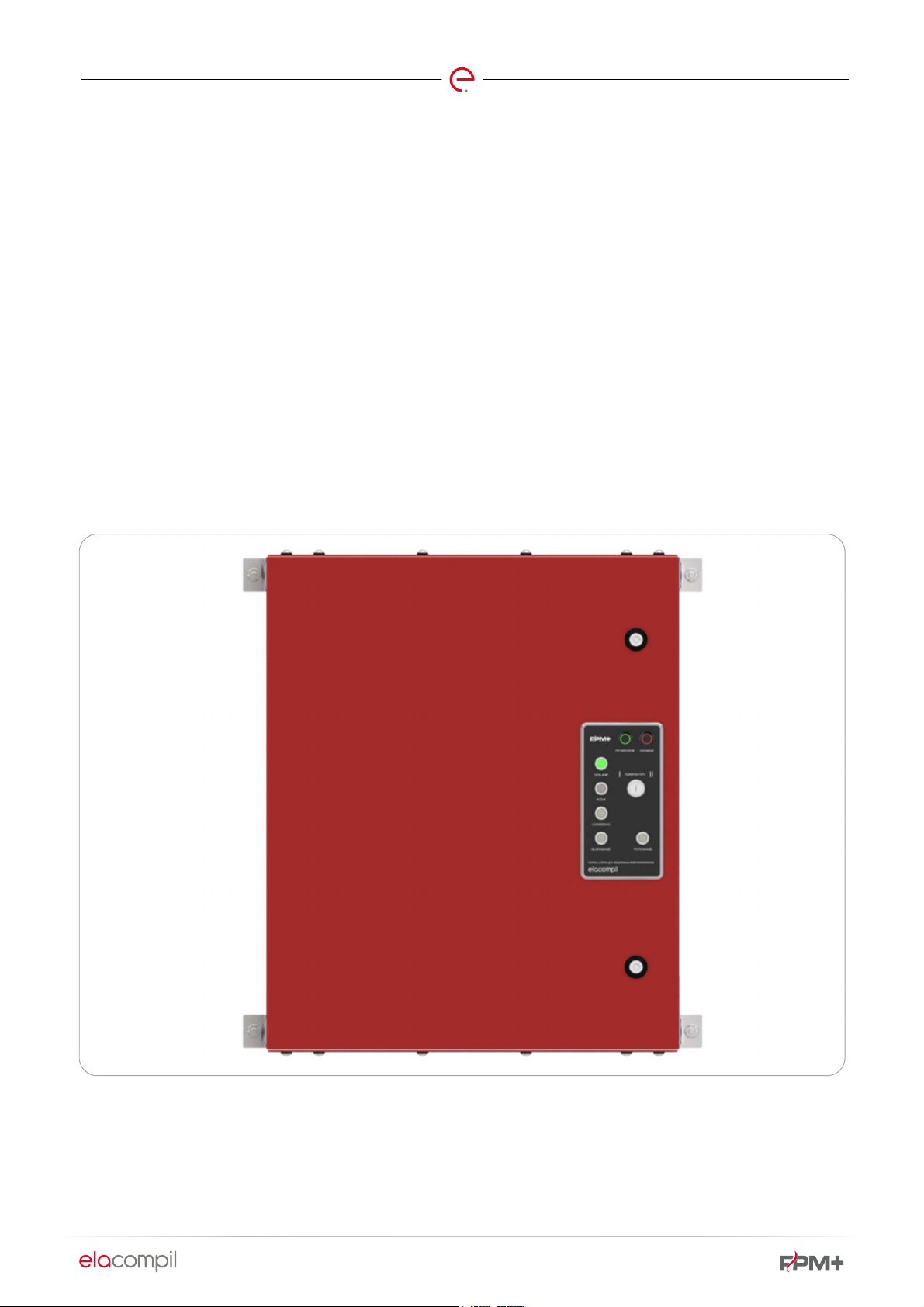
The main unit housing consists of: the housing itself, a
control & alert panel, a power supply with batteries (the
power supply and batteries can be waived upon request and
the unit can be powered from an external certified power
supply), installation pieces (cable grommets, DIN bus bars,
cable trays).
Fig. 3 FPM+ unit housing (MASTER housing)
Page 17
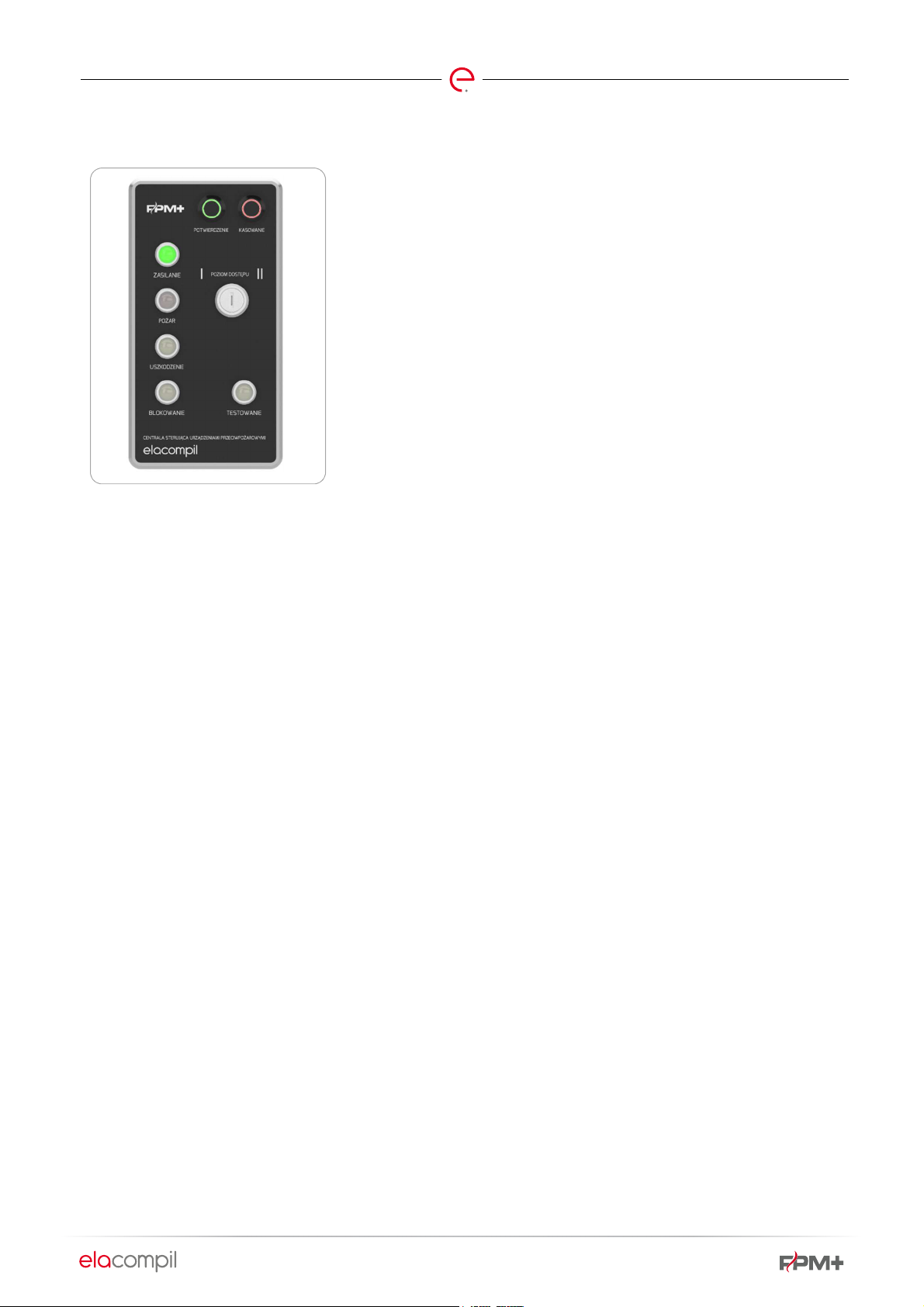
A control & alert panel is located on the main housing of the FPM+ unit, fitted with the following controls:
Page 16 of 78
Fig. 4 Control panel
Confirm
for shutting down voice alarms
Reset
button
button
for a fire reset triggered from access level 2
light
Power
indicates that the unit is powered and working
Malfunction light
indicates that the unit has discovered a malfunction
light
Fire
indicates that the unit is in the fire state
light
Locked
indicates that the unit has certain components in locked state
Page 18
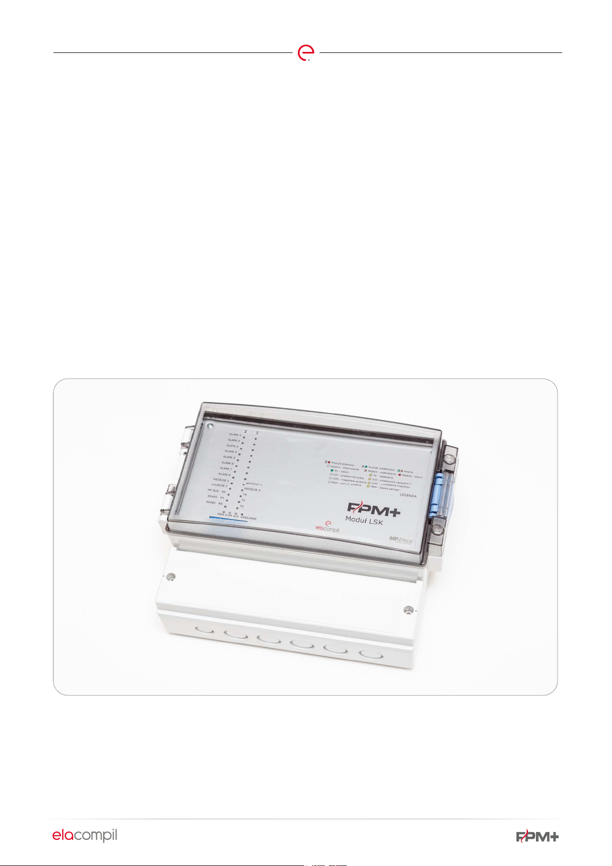
6.2. LSK
Page 17 of 78
The LSK module is designed for controlling and monitoring
actuators and other devices fitted with MP-Bus interface.
Such actuators may include:
fire shut-off damper actuators (e.g. BF24-TL-T-ST),
line actuators of air dampers in HVAC systems, and slide
valves (e.g. LH24A-MP, NM24A-MP, SM24A-MP, GM24A-MP)
SA actuators for dampers and louvres (e.g. LU24A-MP)
actuator valves for water installations (e.g. LV24A-MP-TPC,
NVC24A-MP-TPC)
actuators for water installation valves (e.g. LR24A-MP)
VAV regulators (e.g. LMV-D3-MP)
air pressure regulators (e.g. VRP-M)
Apart from devices supporting the MP-BUS standard, the LSK
module can also control and monitor analog equipment
items, e.g. fire damper actuators. In order to support such
devices, the LSK must be connected to SKC-A module.
The LSK module is also fitted with four potential-free signal
inputs. These inputs can operate in supervised, NO or NC
modes. For the purpose of receiving alarm signals from the
FAS, an input should be configured in line supervision mode.
The primary method of installation of an LSK module is to
place it in a separate housing in the building, near the
equipment it supervises.
Two versions of LSK modules are available: fitted for 230VAC
or 24VAC/VDC power supply. The difference between these
modules is the non-existence of a transformer in the power
system. Besides, the modules are identical and have the
same properties.
Fig. 5 LSK module
Page 19
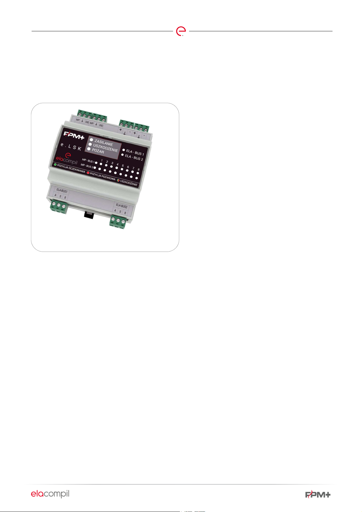
6.3. E.LSK
Page 18 of 78
The e.LSK is a more recent version of LSK, a module
designed for controlling and monitoring actuators and other
devices fitted with MP-Bus interface.
Fig. 6 e.LSK module
Below are the primary differences between e.LSK and LSK:
e.LSK is fitted with two MP-Bus items (1 bus in LSK), capable
of accommodating up to 16 actuators (8 actuators can be
connected to an LSK module);
no trip inputs in e.LSK (there are 4 trip inputs in an LSK
module);
different installation method: by default, e.LSK should be
installed in a multiple-module housing of the FPM+ unit on a
DIN bus bar, while LSK is installed in a separate housing.
The primary method of installation of an LSK module is to
place it in a multiple-module housing of the FPM+ unit, while
an e.LSK can be installed in a separate housing in the
building, near the equipment it supervises. Such additional
housing for e.LSK is the same as that for SKC-A.
e.LSK modules are powered with 24- 40VDC/VAC voltage.
Page 20
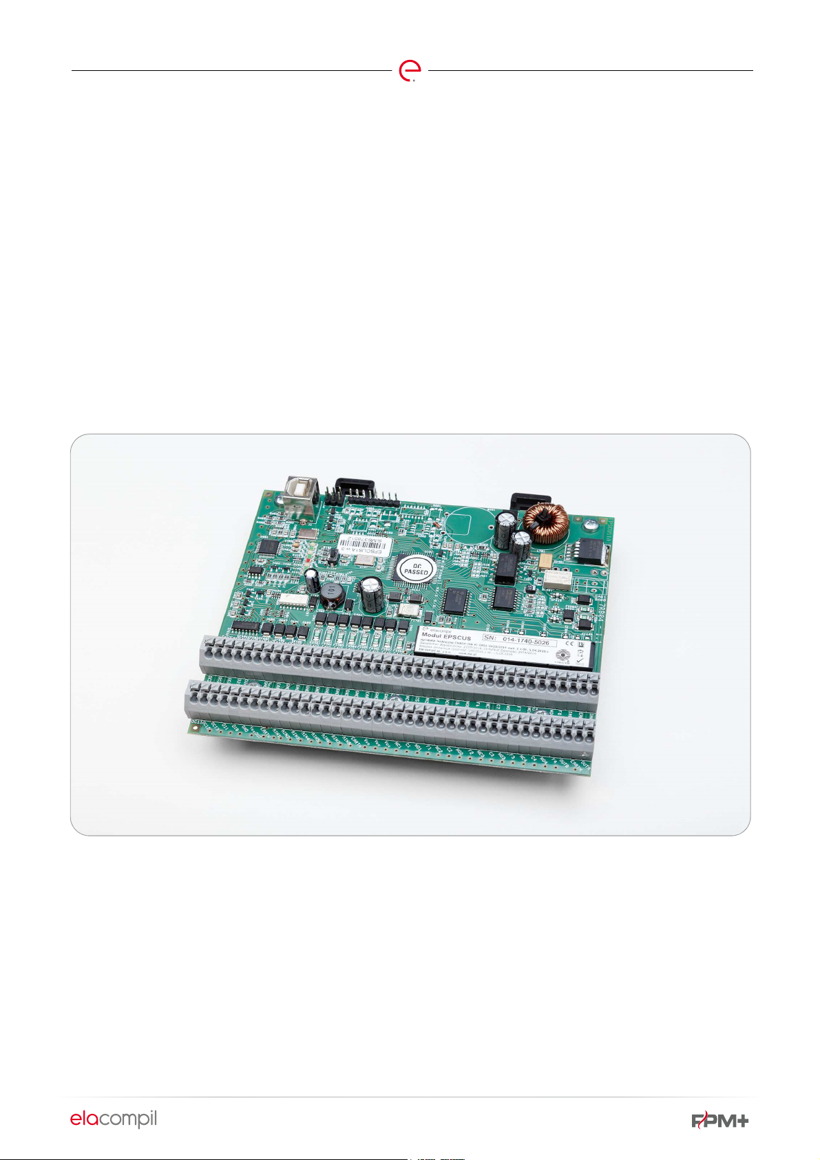
6.4. EPSCUS
Page 19 of 78
EPSCUS is the primary control and monitoring module of an
FPM+ unit. It can receive potential-free signals from external
equipment and systems, and is fitted with 8 relay outputs for
controlling external hardware.
In addition, an EPSCUS module has 6 OC outputs which can
be used for connecting indicator elements, such as lights.
A module adapted to measurement of analog values from
different types of detectors is referenced as EPSCUS(A).
An EPSCUS module can be placed:
in the main housing, together with the MASTER module max. 2 items;
in one of the steel housing versions (OZ-FPMPLUS-xx or
OBZ-FPMPLUS-xx);
in an ABS housing for a single module.
EPSCUS modules are installed in multiple-module housings
on a DIN bus bar.
The choice of the specific housing and number of modules
in a housing depends on the building design and the need to
build a control system for fire safety equipment.
The EPSCUS model is designed for 12-48VDC.
Fig. 7 EPSCUS module
Page 21
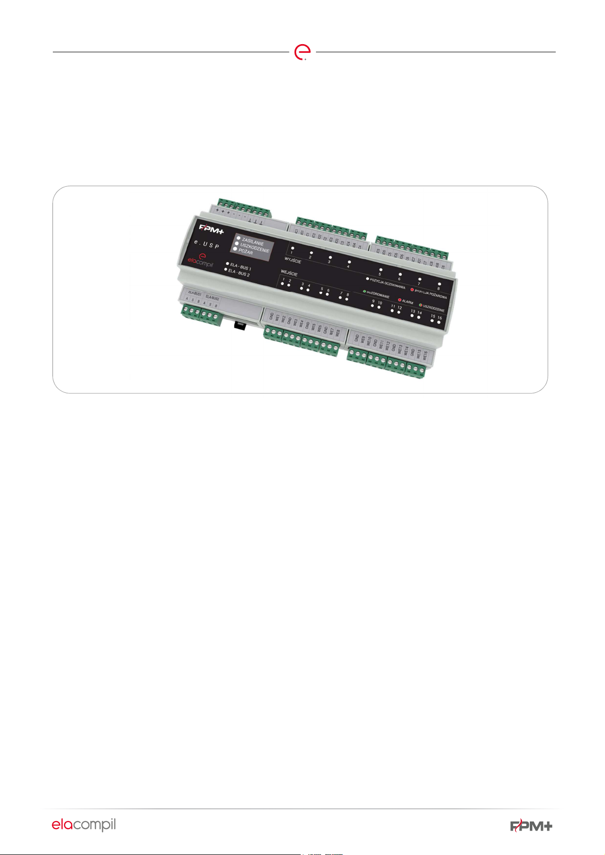
6.5. E.USP
Page 20 of 78
e.USP is the more recent version of the EPSCUS module. It
can receive potential-free signals from external equipment
and systems, analog signals (0 30V or 0-24mA, shared
Fig. 8 e.USP module
ground wire) and is fitted with 8 relay (toggle) outputs
designed for external device control.
Differences between USP and EPSCUS modules:
no OC outputs in e.USP (there are 6 OC outputs in an
EPSCUS module);
e.USP has 16 inputs (EPSCUS - 8 inputs);
higher current capacity of e.USP outputs (up to 5A);
additional indicator items (LEDs) for easier startup and
servicing;
terminals supporting cables with core diameters up
to 2.5mm2 (28-12AWG);
closed DIN bus bar enclosure.
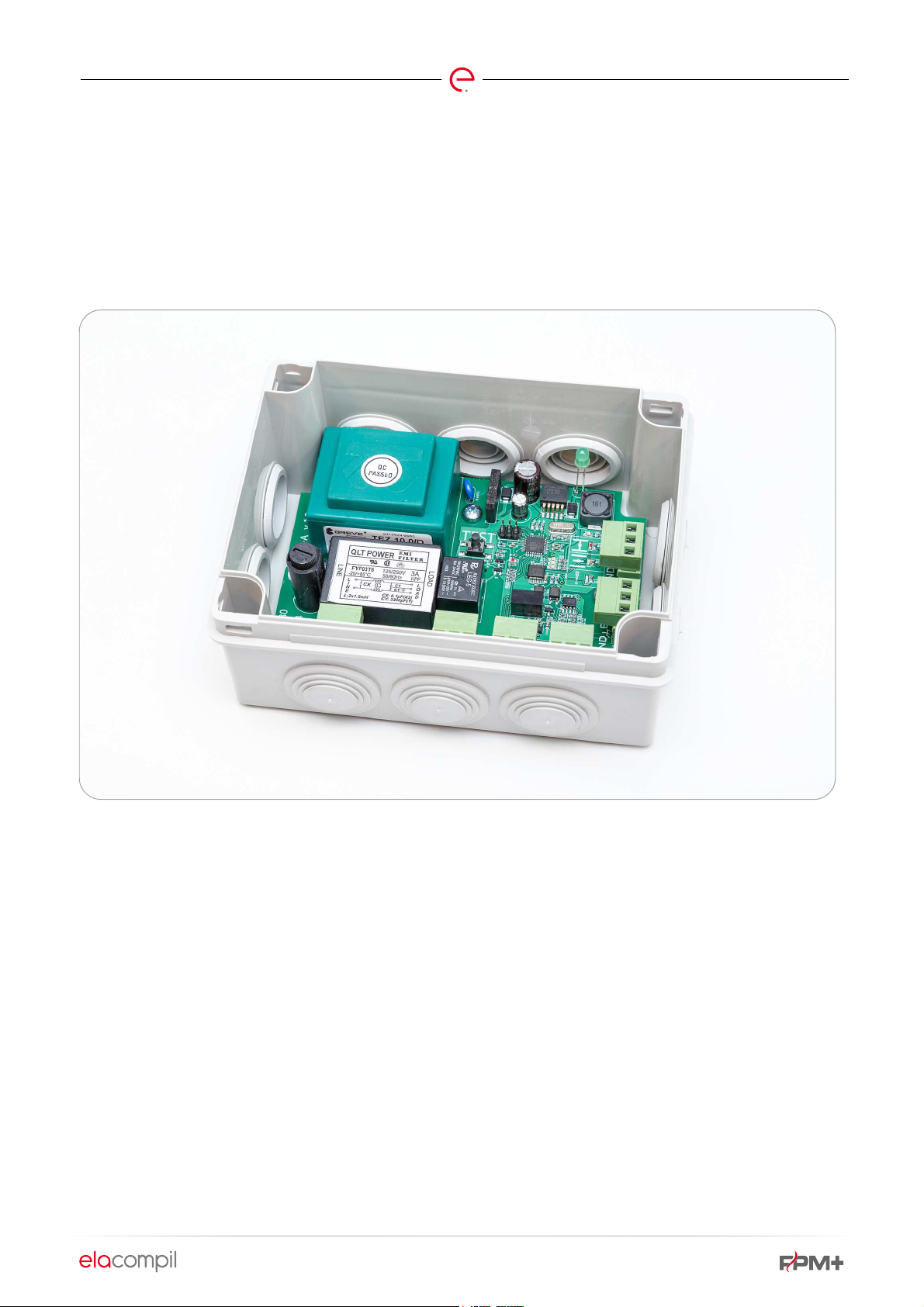
6.6. SKC
SKC modules are designed for powering and monitoring the
service of type BF24TL-T-ST actuators. These actuators are
used to energize fire shut-off dampers.
EPSCUS modules are installed in FPM+ unit housings on a
DIN bus bar. Installation in an additional ABS housing is also
possible, such as the housing for EPSCUS module. The
choice of the specific housing and number of modules in a
housing depends on the building design and the need to
build a control system for fire safety equipment.
The EPSCUS model is designed for 12-48VDC.
A single module supports the connection of a single damper
with a single actuator. It converts ~230V mains voltage to
the supply voltage for ~24V actuator.
Page 22
Page 21 of 78
Fig. 9 SKC module
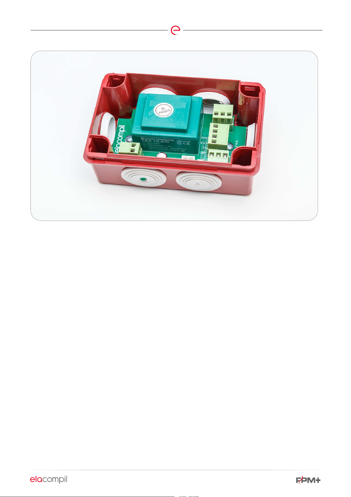
6.7. SKC-A
The function of SKC-A modules is to supervise the service of
analog equipment controlled by 24VDC or 230VAC voltage
input. Such equipment can include fire damper actuators.
The modules are adapted for integration with LSK modules.
The modules are available in 2 versions, depending on
equipment operating voltage:
230V version - for equipment powered from ~230VAC mains
24V version - for equipment powered with 24VDC
The module can be configured for transmission at 230VAC,
24VDC voltage relay output, or as a potential-free output
only.
The module is configured in terms of output signal (230VAC
voltage, 24VDC voltage, potential-free signal) by the
manufacturer. Such setup can also be done by a trained
service operative. In such case, the manufacturer is not
responsible for service personnel errors.
Identification of SKC-A module. According to module
configuration, additional power supply and output data is
provided in the identification.
Identification of
SKC-A-XXX-YYY.
Where:
SKC-A – module type
-XXX – supply voltage
-
-
– 230VAC power supply
-230
– 24VDC power supply
-24
- output type
YYY
-
-
-
– 230VAC output
-230
– 24VDC output
-24
– relay output
-R
Page 23
Example:
Example:
Page 22 of 78
Example:
SKC-A-230-230
– SKC-A module
configured for 230VAC voltage supply
and generating 230VAC voltage signal
at output
SKC-A-230-24
configured for 230VAC voltage supply
and generating 24VDC voltage signal
at output
– SKC-A module
SKC-A-230-R
– SKC-A module
configured for 230VAC voltage supply
and generating potential-free signal at
output
NOTE: For technical reasons, the module cannot be configured according to the pattern SKC- A- 24- 230
Fig. 10 SKC-A module
6.8. FPM+ BUS REPEATER MODULE
The function of FPM+ bus repeater module is to provide bus
signal gain. It is used in layouts with very large distances
between modules, and in high-interference environments
(primarily at industrial sites).
The FPM+ bus repeater module is manufactured by MOXA
as TCC-120I module, but will be tuned by the control unit
manufacturer to the operating parameters of the FPM+
control unit bus. The control unit manufacturer cannot
warrant proper operation of the bus if a TCC-120I module is
used without appropriate tuning.
The FPM+ bus repeater module is installed inside the
housing of an FPM+ unit module and powered with the
supply voltage dedicated to that module. The FPM+ bus
repeater module will always be installed so that one of the
FPM+ bus repeater module buses extends outside the
housing in which the module is installed and the other bus
connects to an EPSCUS or MASTER module installed locally.
Page 24
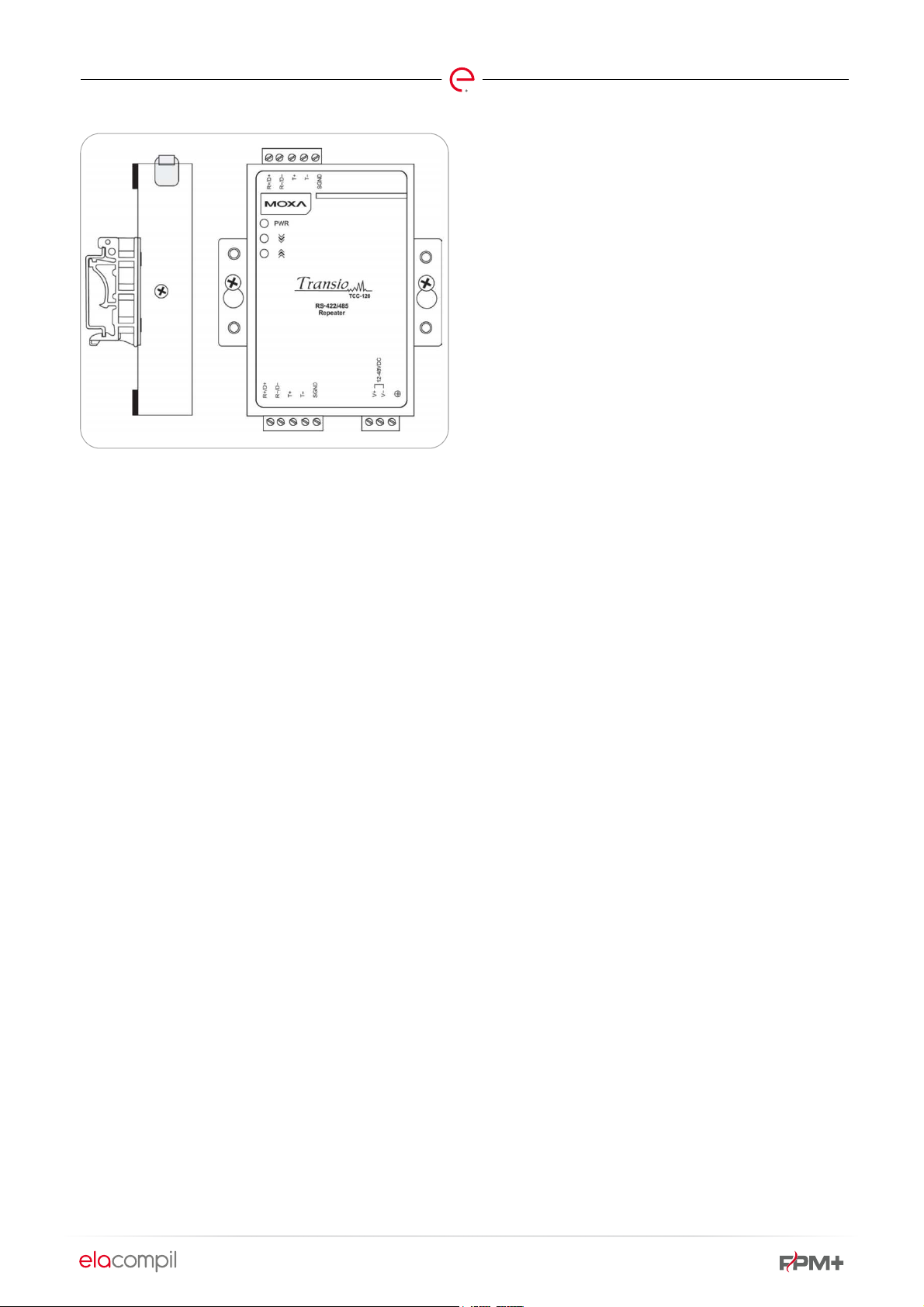
Fig. 11 FPM+ bus repeater module
The FPM+ bus repeater module is not addressable and
invisible for the FPM+ control unit. Any damage to that
module can be diagnosed on the basis of broken bus
continuity. If the control unit generates an alert of loss of bus
continuity:
Check the power supply to FPM+ bus repeater module(s);
Check the connection between the FPM+ bus repeater
module and other FPM+ unit modules;
Check the connections between other FPM+ unit modules.
Damage to the bus is indicated by a joint damage alert
(DAMAGE indicator light on the unit’s control panel), in the
visualization system and in FPM Configurator.
Page 23 of 78
Page 25

Page 24 of 78
7. CONNECTING MODULES
The modules must be connected with the use of appropriate precautions, in accordance with the applicable guidelines. Failure
to comply with the applicable requirements can have an adverse effect on the functioning of the control unit and result in a
security impairment.
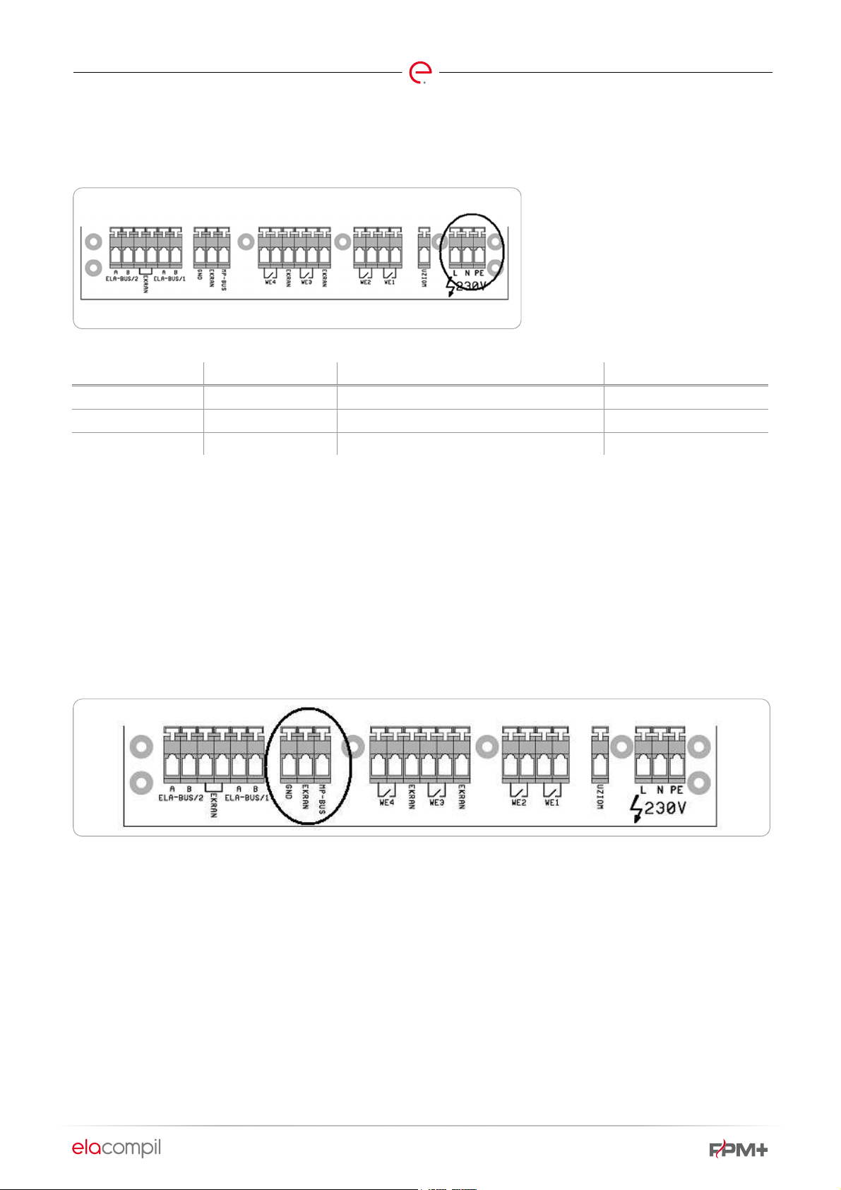
7.1. FPM-X-YY-ZZ HOUSINGS
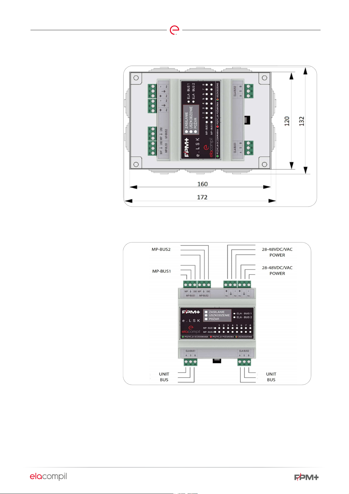
Below is a presentation of power
supply connector and bus layout for
an FPM+ unit.
Fig. 12 FPM+ unit power supply connector and bus layout
Table 2 Identification and functions of FPM-X-YY-ZZ housing
ITEM IDENTIFICATION FUNCTION
1 230VAC L Power supply ~230V – L wire
2 230VAC N Power supply ~230V – N wire
3 PE Power supply ~230V – protective wire
4 +24 VDC Internal FPM+ power supply +24 VDC
5 0 VDC Internal FPM+ power supply 0 VDC
6 ELA-BUS1 A ELA-BUS1 A
7 ELA-BUS1 B ELA-BUS1 B
8 SCREEN ELA-BUS1 and ELA-BUS2 screens
9 ELA-BUS2 A ELA-BUS2 A
10 ELA-BUS2 B ELA-BUS2 B
11 USZK. ZAS. + Power supply failure signal input
12 USZK. ZAS. - Power supply failure signal input
Page 26

Page 25 of 78
7.2. EPSCUS
The diagram below shows the layout of EPSCUS module interfaces. Input and output connections are identified, which we will
be using while connecting the EPSCUS module supplied in an ABS housing. When the EPSCUS module is ordered together with
other modules in a steel housing, the interfaces are already connected.
Fig. 13 EPSCUS module connectors
Bus interfaces,
i.e. unit bus input and unit bus output, are identified
as INA, INB for inputs and OUTA, OUTB for outputs.
Relay output interfaces
are identified as Cx, NOx, NCx. These
outputs are designed to control external equipment.
Auxiliary terminal
is identified as Fx and can be used for example
to connect an external resistor.
Power supply connectors: Vcc
– 24VDC power supply, polarity +;
GND – power supply 24VDC polarity
is the identification of an input interface no. x and GND is the
AINx
input neutral (shared with power)
OC type inputs
are identified as follows: OC11, OC12, OC13, OC21,
OC22, OC23.
EARTH terminals are used for connecting cable shields
7.3. E.UPS
e.USP modules are installed in
multiple-module housings (FPM-XYY-ZZ) on a DIN bus bar, or in a
plastic housing and on a DIN bus
bar as well.
An e.UPS module has 16
analog/digital inputs. Neutral wiring
is shared for all the inputs. In
addition, the module has 8 potentialfree (relay) outputs.
Module power supply is connected
to the two terminals in the left upper
section of the housing. The unit bus
is connected in the left bottoms
section of the housing. The bus
should be set up with shielded cable
- terminal S is used to connect the
bus line shielding.
Page 27

Page 26 of 78
Fig. 14 e.USP module in a plastic housing
Fig. 15 Connection of e.USP module
7.4. LSK
The gland chokes identified on the drawing as 1, 2, 3, and 6
should be removed from every LSK controller. If the design
sets out fire zone triggering via FACP unit modules and if
signals for trigger inputs should be connected to a specific
module, the following gland chokes should be removed:
For gland identified as 4 on the drawing - when WE3 and/or
WE4 input is used;
For gland identified as 5 on the drawing - when WE2 and/or
WE1 input is used.
Glands should be tightened with significant force so that
they have no slack in the housing; however, the installer
should be careful not to damage the glands.
Gland 1 is manufactured to size PG9, the remaining glands
are sized PG11.
Fig. 16 Gland chokes
Page 28
7.4.1. CONNECTING TO POWER SUPPLY
The power terminal is located to the right of the module terminal strip.
Fig. 17 Connecting LSK to power supply
To connect to power supply, draw the
supply cable through gland no. 6, then
press the terminal levers with a flatblade screwdriver (width 3-4mm) and
insert the separate cable cores into the
right slot (see the table below).
.
IDENTIFICATION DESCRIPTION WIRE COLOR TERMINAL COLOR
Page 27 of 78
L
N
PE
Phase Other than blue and yellow-green Red
Neutral Blue White
Protective Yellow-green Green
NOTE: For your own safety, this operation should be performed after shutting down ~230V, 50Hz power supply.
7.4.2. CONNECTING FIRE DAMPERS
The LSK module is designed to operate with dampers fitted
with MP-BUS actuators. Connect the MP-Bus control cable
on LSK side to the interface identified as MP-BUS.
To do this, draw the fire damper connection cable through
gland no. 3, then press the MP-BUS, GND and SHIELD
terminal levers with a flat-blade screwdriver (width 3-4mm)
and insert the separate cable cores into the corresponding
terminals. Terminal colors correspond to YnTKSY cable core
colors to facilitate the connection (blue to blue, white to
white).
Fig. 18 Connecting fire dampers to LSK
Page 29

7.4.3. CONNECTING ELA-BUS COMMUNICATION BUS LINES
Page 28 of 78
To connect several LSK modules, use ELA-BUS. An LSK
controller features two ELA-BUS ports identified as ELABUS/1 and ELA-BUS/2.
To connect ELA-BUS lines to a module, draw the bus cables
(two cables must reach every module) through glands 1 and
Fig. 19 Connecting ELA-BUS lines in LSK
7.4.4. CONNECTING WE1-WE4 TRIGGER INPUTS
2 (with the cables entering the housing separately), then
press the A, B and SHIELD terminal levers with a flat-blade
screwdriver (width 3-4mm) and insert the separate cable
cores into the corresponding terminals. Terminal colors
correspond to YnTKSY cable core colors to facilitate the
connection (blue to blue, white to white, shielding to green).
Fig. 20 Connecting WE1-WE4 trigger inputs in LSK
Trigger inputs are connected according to the instructions given in section 4.
Page 30
7.5. E.LSK
e.LSK modules are installed in
multiple-module housings (FPM-X-YYZZ) on a DIN bus bar, or in a plastic
housing and on a DIN bus bar as well.
Page 29 of 78
An e.LSK module is fitted with two
control unit bus inputs (at the bottom
of the housing, on both sides) and two
MP-BUS bar inputs (left upper section
of the housing).
Module power supply is connected to
the two terminals in the right upper
section of the housing.
Fig. 21 e.LSK module in a plastic housing
Fig. 22 Connection of e.LSK module
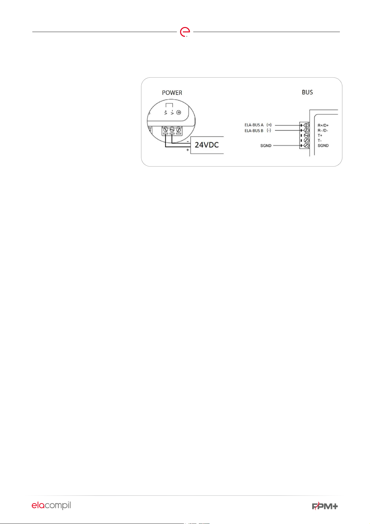
7.6. SKC-A
The diagrams below present the main methods of connecting SKC-A modules to power supply and to the control unit.
Page 31

Page 30 of 78
Fig. 23 SKC-A to control unit
and power supply wiring
diagram
Fig. 24 SKC-A to control unit
and power supply wiring
diagram
Page 32

Page 31 of 78
Fig. 25 SKC-A to control unit
and power supply wiring
diagram
Page 33
7.7. FPM+ BUS REPEATER
An FPM+ bus repeater module is
powered with 24VDC voltage. It is
fitted with two ports for connecting
ELA-BUS.
Page 32 of 78
Fig. 26 FPM+ bus repeater module connection diagram
Page 34

8. MAIN HOUSINGS FOR CONTROL UNIT MODULES
According to actual needs on site, the designer is able to
choose housing types and sizes, and therefore the number
of modules in a single location.
8.1. EPSCUS
Page 33 of 78
An EPSCUS module can be housed in an ABS housing for a single module.
EPSCUS modules are also installed in multiple-module housings on a DIN bus bar.
The choice of the specific housing and
number of modules in a housing
depends on the building design and the
need to build a control system for fire
safety equipment.
The EPSCUS model is designed for 1248VDC. Power can be supplied from a
certified fire rated power supply.
In the selection of cable thickness for
connections, power consumption and
voltage drops should be considered.
Power can be supplied from a certified
fire rated power supply.
Follow the guidelines for installation to
maintain a proper level of security and
to avoid interference with the
protection level.
Each module must be permanently
attached to building structure
components or to other items
permanently affixed to the building
structure.
Fig. 27 EPSCUS module in housing.
8.2. LSK
LSK module is enclosed in a plastic
ABS housing and is fit for user
installation on site.
8.3. SKC
Follow the guidelines for installation to maintain a proper level of security and to
avoid interference with the protection level.
The module needs to be affixed permanently.
Page 35

Page 34 of 78
SKC module is enclosed in a plastic ABS housing and is fit
for user installation on site.
Follow the guidelines for installation to maintain a proper
level of security and to avoid interference with the
protection level.
Considering its low output powers, it is recommended to
use supply cables with as small core diameter as possible.
The module needs to be affixed permanently.
8.4. SKC-A
SKC-A module is enclosed in a plastic ABS housing and is
fit for user installation on site.
Follow the guidelines for installation to maintain a proper
level of security and to avoid interference with the
protection level.
The thinnest possible wire (3x0.75) should be used when
the module is powered with 230V voltage.
The module needs to be affixed permanently.
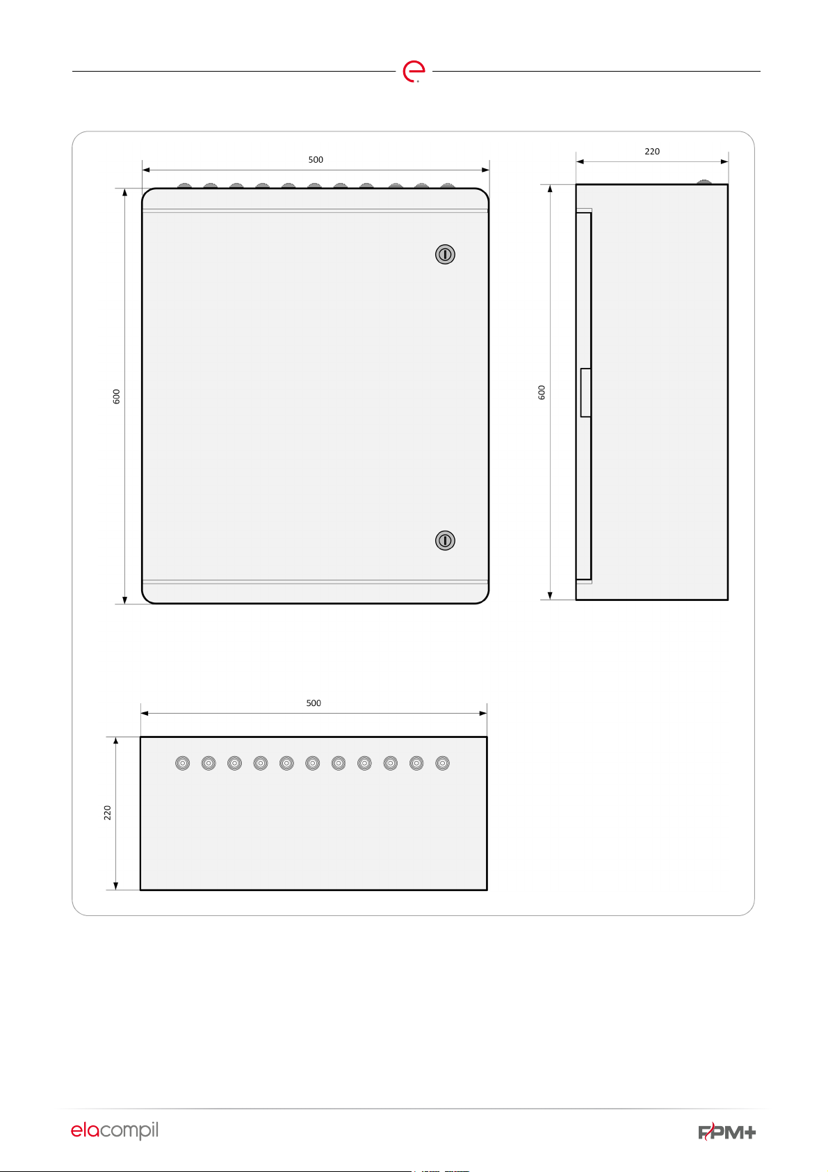
8.5. MAIN HOUSING OF THE CONTROL UNIT, TYPE FPM-M-YY-ZZ
The main housing of the control unit and the basic multiplemodule housings are designed on the basis of single range
steel cabinets. This ensures identical housing attachment
technique, connection tightness and effective installation of
fixtures.
The differences between the specific types of housings are
concerned with dimensions (5 basic dimensions) and
housing fixtures. The fixtures include: cable penetrations,
equipment mounting bars, cable trays.
The main enclosure of a control unit type FPM-M-YY-ZZ is
fitted by default with a MASTER module and an indicator
panel with LEDS and pushbuttons.
Depending on actual needs, it can be fitted with a power
supply unit complete with batteries. This housing can
accommodate a maximum of two EPSCUS modules
together with the MASTER.
The dimensions of the housing are: (HxWxD) 600x500x250;
available colors: RAL3000
Fig. 28 FPM+ unit housing
Page 36

8.6. FPM-X-YY-ZZ
Page 35 of 78
The main housing of the control unit and the basic multiplemodule housings are designed on the basis of single range
steel cabinets. This ensures identical housing attachment
technique, connection tightness and effective installation of
fixtures.
The differences between the specific types of housings are
concerned with dimensions (6 basic dimensions) and
housing fixtures. The fixtures include: cable penetrations,
equipment mounting bars, cable trays.
Item
1
2
3
ENCLOSURE
SYMBOLS
MAX. EPSCUS CONTROLLERS
FPM-2-YY-ZZ 2 12 x O/C outputs
FPM-4-YY-ZZ 4 24 x O/C outputs
FPM-6-YY-ZZ 6 36 x O/C outputs
FPM-X-YY-ZZ line housings, designed to accommodate
multiple modules, are available in five basic sizes. They can
be fitted with power supplies with different power ratings
and batteries with different capacities. Depending on the
size of a specific housing, it can accommodate different
numbers of modules, and therefore it offers different
numbers of unit inputs and outputs.
MAX. INPUTS/OUTPUTS
16 x relay outputs
16 x analog or digital inputs
32 x relay outputs
32 x analog or digital inputs
48 x relay outputs
48 x analog or digital inputs
4
5
FPM-8-YY-ZZ 8 48 x O/C outputs
FPM-10-YY-ZZ 10 60 x O/C outputs
A detailed description of the housing versions is presented
in Appendix 2.
64 x relay outputs
64 x analog or digital inputs
80 x relay outputs
80 x analog or digital inputs
On special order, control unit housings with different
capacity or dimensions can be produced. The housings
must meet the isolation criteria (min. IP42). The range of
housings and ranges are presented in Appendix E.
Page 37

8.7. FPM-U-X-X-X-X-X AND FPM-L-X-X-X-X-X
Page 36 of 78
The main housing of the control unit and the basic multiplemodule housings are designed on the basis of single range
steel cabinets. This ensures identical housing attachment
technique, connection tightness and effective installation of
fixtures.
FPM-U-x-x-x-x-x and FPM-L-x-x-x-x-x line housings are the
extension of line FPM-X-YY-ZZ housings. The primary
difference between the particular lines of housings is the
layout of cable trays inside the housing, and the cable exit
pattern. FPM-U-x-x-x-x-x and FPM-L-x-x-x-x-x line housings
are primarily fit for installation of e.LSK and e.USP modules.
Detailed specifications of the housings are presented in
Appendix 3 and assembly drawings of the housings are
given in Appendix D.
8.8. PLASTIC MULTIPLE-MODULE HOUSINGS
Multiple-module plastic housings are designed to
accommodate multiple modules and are available in three
basic sizes. They can be fitted with power supplies with
different power ratings and batteries with different
HOUSING
OUTER DIMENSIONS
CP5004 400 x 500 x 175 mm 350 x 455 x 150 mm 3 kg
CP5005 400 x 600 x 200 mm 355 x 550 x 175 mm 4 kg
CP5008 500 x 600 x 220 mm 455 x 550 x 195 mm 5 kg
capacities. Depending on the size of a specific housing, it
can accommodate different numbers of modules, and
therefore it offers different numbers of unit inputs and
outputs.
INNER DIMENSIONS
WEIGHT
Page 38

Page 37 of 78
Fig. 29 CP5004 type housing
Page 39

Page 38 of 78
Fig. 30 CP5005 type housing
Page 40
Page 39 of 78
Fig. 31 CP5008 type housing
Page 41

9. ASSEMBLY INSTRUCTIONS
9.1. BUS
Page 40 of 78
A single section of bus line between modules can reach
1200m length. The acceptable MP-Bus length is 600m
(determined as the sum of the lengths of cable sections
within the bus and not the largest distance between
appliances.
Bus cables should not be laid near power cables.
If the system is used for smoke extraction, the bus line,
motor line and the terminal rooms must be designed to E90.
9.2. SHIELDING
In order to comply with the interference immunity
requirements as per PN-EN 61000-6-2:2008
Electromagnetic compatibility (EMC), Part 6-2: General Immunity requirements for the industrial environment”, all
bus connections (control unit bus, MP-BUS) must be made
of shielded cables (e.g. YnTKSYekw, HTKSHekw).
It is further recommended to connect input signals (to
EPSCUS module inputs) using shielded cables.
9.3. EXTERNAL POWER SUPPLIES
Moreover, make sure that the bus incoming and outgoing
cables are laid as separate routes. In this case, construction
laws must be specifically complied with.
LSK, EPSCUS and MASTER modules must be connected
into a single loop. No other connections can be established
(additional branch lines from the main loop).
MP-Bus modules cannot be designed in a loop layout. Linear
or star topology is acceptable.
Shielding should be continuous, connected to shared PE
potential. It is recommended to join ELA-BUS shields
together (e.g. by twisting or connecting to appropriate
terminals in the modules).
All steel housings (FPMPLUS-M-xx-xx, OBZ-FPMPLUS-xx
and OZ-FPMPLUS-xx) should be connected to PE potential.
It is recommended to establish a direct connection with the
building structure earthing (hoop iron).
If external power supplies are used, each power supply
should be located as close as possible to the control unit
10. TYPES OF INPUTS IN THE UNIT
Unit inputs can vary in terms of type and function (a
description of their functions is given in section 6). Both
these properties are assigned in FPM+ Configurator.
Type of input indicates the electrical characteristics of the
input.
housing with modules. In addition to power, power supply
failure signal should be connected to the unit as well.
Inputs differ in terms of response and auxiliary external
pieces (if any).
Input types are defined for LSK, EPSCUS and EPSCUS(A)
controllers.
Not all the types enumerated below are available for every
controller.
Page 42
10.1. INPUT TYPE: UNUSED
Page 41 of 78
Unused inputs are present in LSK, EPSCUS and EPSCUS(A)
modules.
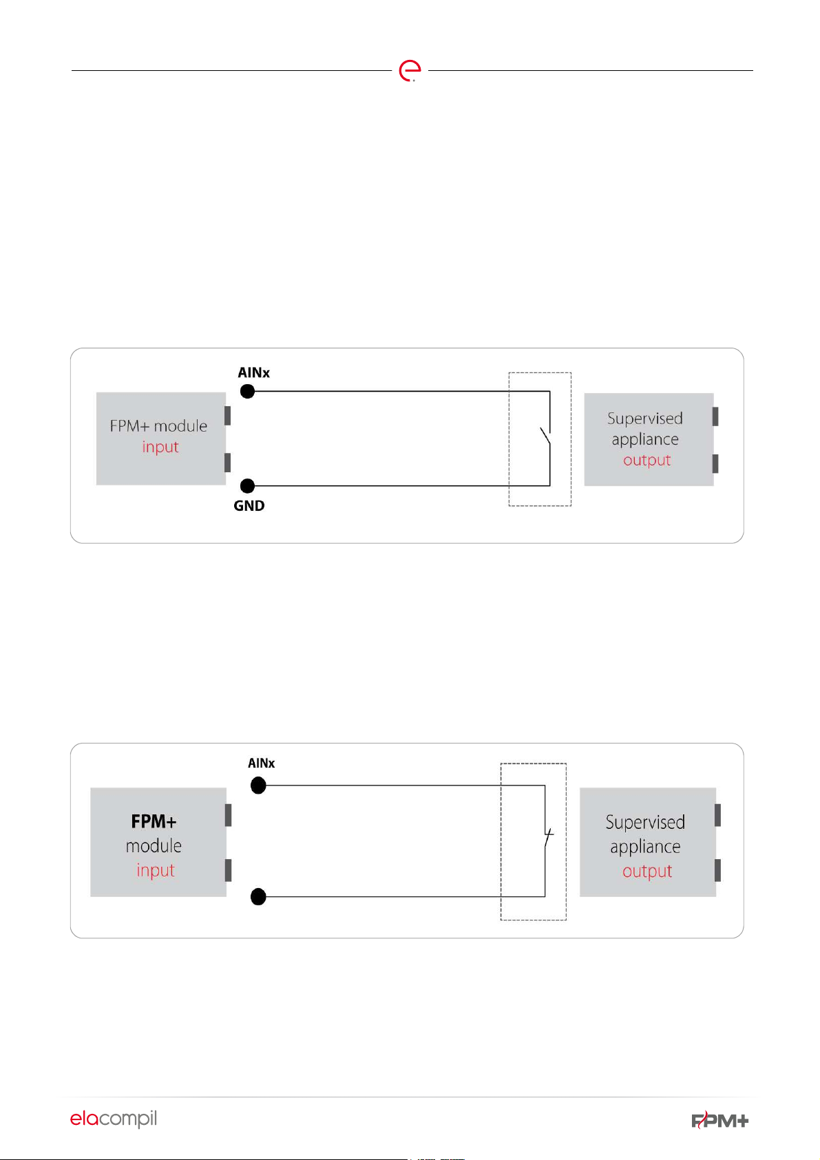
10.2. INPUT TYPE: DIGITAL NO
Digital NO inputs are present in LSK and EPSCUS modules.
A digital NO input is a digital input without line state
supervision, for direct connection of relay contact.
Fig. 32 Digital NO input diagram
An unused input is not utilized in the system and does not
report any state, irrespective of the connected alarm.
Open state is alerted as idle, shorting means an alarm.
10.3. INPUT TYPE: DIGITAL NC
Digital NC inputs are present in LSK and EPSCUS modules.
A digital NC input is a digital input without line state
supervision, for direct connection of relay contact.
Fig. 33 Digital NC input diagram
Open state is indicated as alarm, shorting - idle.
Page 43

10.4. INPUT TYPE: DIGITAL THREE-STATE
Digital three-state inputs are present in LSK and EPSCUS
modules.
Inputs of this type will indicate either of the three states:
open, closed, or intermediate.
10.5. INPUT TYPE: ANALOG RESISTIVE
Page 42 of 78
It is used for such functions as damper operation, where the
damper status can be verified with the right selection of
resistors.
Analog resistive inputs are present in EPSCUS modules.
They are used to measure the value of connected resistance.
10.6. INPUT TYPE: DIGITAL SUPERVISED NO
Digital supervised NO inputs are present in EPSCUS
modules.
A digital supervised NO input is a digital input with line state
monitoring. Monitoring is done via a connected NO contact
that triggers resistor signal.
Analog resistive inputs do not trigger alarms.
The resistance values are the following: 3.3kOhm for idle,
1kOhm for alarm.
This input indicates line failure if the line resistance value is
outside these two values.
Fig. 34 Digital supervised NO (2EOL/NO) input diagram
10.7. INPUT TYPE: DIGITAL SUPERVISED NC
Digital supervised NC inputs are present in EPSCUS
modules.
A digital supervised NC input is a digital input with line state
monitoring. Monitoring is done via a connected NC contact
that triggers resistor signal.
The resistance values are the following: 1kOhm for idle,
3.3kOhm for alarm.
This input indicates line failure if the line resistance value is
outside these two values.
Page 44

Fig. 35 Digital supervised NC (2EOL/NC) input diagram
10.8. INPUT TYPE: ANALOG 0-5V
Analog 0-5V inputs are present in EPSUS(A) modules.
Analog 0-5V inputs accept signals from the range of 0-5V.
If monitoring is to cover other voltages than those in 0-5V
range, use a resistor divider so as to avoid exceeding the 5V
threshold.
Page 43 of 78
An additional safeguard is used to protect the system
against the consequences of exceeding the permitted
voltage value.
Example function of an analog 0-5V input is for voltage
supervision.
10.9. INPUT TYPE: ANALOG 4-20MA
Analog 4-20mA inputs are present in EPSUS(A) modules.
Analog 4-20mA inputs accept 4-20mA signal (where an additional 249Ohm resistor is required).
Fig. 36 Analog 4-20mA input diagram
Page 45

Page 44 of 78
11. TYPES OF OUTPUTS IN THE UNIT
Unit outputs can vary in terms of type and function (description in section 7). Depending on their type, outputs can control
various appliances, such as lifts, escalators, analog actuators, other actuators, or indicator lights.
11.1. OUTPUT TYPE: RELAY
Relay outputs are designed to control external equipment.
An EPSCUS module is fitted with eight relay outputs.
An auxiliary terminal F is located at each relay output, which
can be used for example to connect an external resistor.
11.2. OUTPUT TYPE: OPEN COLLECTOR
Open Collector outputs can be used for connecting indicator
elements, such as lights.
An external relay with 12V coil can be connected to an Open
Collector output and in such case, a flyback diode should be
additionally used.
An EPSCUS module is fitted with six Open Collector outputs.
11.3. OUTPUT TYPE: ACTUATORS AND
APPLIANCES COMPATIBLE WITH MPBUS STANDARD
Actuators and appliances compatible with the MP-Bus
standard are designed for monitoring and controlling
appliances conforming to MP-Bus standard that have
firefighting and utility functions.
Page 46

12. INPUT FUNCTIONS
An input function indicates the logical function of a specific input in the system.
The function of each specific input is defined in FPM+ Configurator.
Not all functions are available for each input.
Page 45 of 78
12.1. INPUT FUNCTION: DISABLED
This input is not used in the system.
12.2. INPUT FUNCTION: FIRE ALARM
An input for connecting a fire alarm signal from a fire alarm
control panel or any other signal that will trigger a fire
scenario.
12.3. INPUT FUNCTION: SMOKE ALARM IN
A DUCT
An input for connecting a smoke detectors put in the duct. If
an alarm occurs on this input, the fan associated with that
input will be switched off.
12.4. INPUT FUNCTION: SMOKE ALARM IN
AIR INTAKE
An input for connecting a smoke detectors put in the duct. If
an alarm occurs on this input, the fan associated with that
input will be switched off.
12.5. INPUT FUNCTION: SMOKE WARNING
IN AIR INTAKE
Firefighting action signal input. Active state at this input
indicates that additional relay outputs are operated in
EPSCUS modules.
12.9. INPUT FUNCTION: TECHNICAL ALARM
A general purpose input for connecting any external signals
to be displayed by the visualization system.
12.10. INPUT FUNCTION: VENTILATION
Ventilation signal connection input. Active state at this input
indicates that the system will trigger fan function in
staircases in ventilation mode.
12.11. INPUT FUNCTION: FORCED AIR
SUPPLY FROM DOWNSTAIRS
Input enforcing continuous air supply to staircases from the
bottom, irrespective of temperature measurement results.
12.12. INPUT FUNCTION: FORCED AIR
SUPPLY FROM UPSTAIRS
Input enforcing continuous air supply to staircases from the
top, irrespective of temperature measurement results.
An input for connecting a smoke detectors put in the duct. If
an alarm occurs on this input, it will only be displayed in the
visualization system.
12.6. INPUT FUNCTION: SMOKE WARNING
IN A DUCT
An input for connecting a smoke detectors put in the duct. If
an alarm occurs on this input, it will only be displayed in the
visualization system.
12.7. INPUT FUNCTION: FIRE RESET
A system reset input - all the appliances will be reset to idle
positions and the inputs (actuators) will return to ready
state.
12.8. INPUT FUNCTION: FIREFIGHTING
ACTION
12.13. INPUT FUNCTION: INDICATOR LIGHT
TEST
Switching all inputs identified as indicator lights on for
several seconds.
12.14. INPUT FUNCTION: MEASUREMENT
This input is responsible for direct presentation of measured
values (e.g. voltage, current). It can be used to monitor
continuous type variables.
An input with the measurement function is not involved in
system control.
12.15. INPUT FUNCTION: VENTING OPEN
Control of actuators responsible for opening smoke
dampers, windows for venting.
Page 47
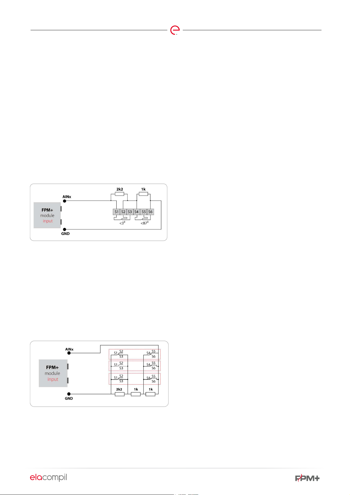
Page 46 of 78
12.16. INPUT FUNCTION: VENTING CLOSE
Control of actuators responsible for opening smoke
dampers, windows for venting.
12.17. INPUT FUNCTION: DRIVE START TEST
Checking the operating capacity of smoke damper
actuators.
12.18. INPUT FUNCTION: POWER FAILURE
This input is presented as a power failure, e.g. from an
external power supply.
12.19. INPUT FUNCTION: LIMIT SWITCH
Damper terminals, e.g. damper open/close sensors, are
connected to this input.
Fig. 37 Limit switch input diagram
Resistance values:
1k – closed
2k2 – open
3k2 – intermediate position
12.21. INPUT FUNCTION: MANUAL CONTROL
In manual control, the unit stops responding to automatic
alarms from the fire alarm control panel (a fire reset occurs,
switching the appliances to idle mode).
12.22. INPUT FUNCTION: MANUAL FIRE
ALARM
Manual input of a fire alarm from FACP, for example using
the control panel.
12.23. INPUT FUNCTION: SMOKE DETECTOR
ALARM
If an alarm is notified from a smoke detector during a fire, a
fan will be shut down.
If a smoke position is set for a damper, it will switch to that
position at this alarm.
12.24. INPUT FUNCTION: SMOKE DETECTOR
WARNING
If a warning is notified from a smoke detector, it will be
indicated but will not cause any change of system operation
control.
12.25. INPUT FUNCTION: EVACUATION WITH
FIREFIGHTING ACTION
Firefighting action signal input. Active state at this input
indicates that additional relay outputs are operated in
EPSCUS modules.
12.20. INPUT FUNCTION: LIMIT SWITCH
GROUP
Damper terminals, e.g. damper open/close sensors, are
connected to this input.
Fig. 38 Limit switch group input diagram
Resistance values:
3k2 – closed,
2k2 – open,
1k – intermediate position
12.26. INPUT FUNCTION: GENERAL ALARM
A general purpose input for connecting any external signals
to be displayed by the visualization system.
12.27. INPUT FUNCTION: PRESSURE
CONTROL
An input forcing control based on pressure and not
temperature measurement results.
12.28. INPUT FUNCTION: EXTERNAL
TEMPERATURE SENSOR
Temperature measurement, result in degrees Celsius *10.
The result of measurement is responsible for fan action in
the assigned zone.
Page 48

Page 47 of 78
12.29. INPUT FUNCTION: INTERNAL
TEMPERATURE SENSOR
Temperature measurement, result in degrees Celsius *10.
The result of measurement is responsible for fan action in
the assigned zone.
12.30. INPUT FUNCTION: UPPER PRESSURE
SENSOR
Pressure measurement, result in Pascals. The result of
measurement is responsible for fan action in the assigned
zone.
12.31. INPUT FUNCTION: BOTTOM
TEMPERATURE SENSOR
Pressure measurement, result in Pascals. The result of
measurement is responsible for fan action in the assigned
zone.
Page 49

13. OUTPUT FUNCTIONS
Unit outputs can vary in terms of function. The function of each specific output is defined in FPM+ Configurator.
Not all functions are available for each output.
Page 48 of 78
13.1. OUTPUT FUNCTION: NORMAL FAN
SWITCH ON
An output for switching on a fan (via an inverter or motor
module) assigned to normal zone.
13.2. OUTPUT FUNCTION: REVERSE FAN
SWITCH ON
An output for switching on a fan (via an inverter or motor
module) assigned to reverse zone.
13.3. OUTPUT FUNCTION: UPPER FAN
ROTATION DIRECTION
An output for changing inverter setup for the purpose of
altering the air flow direction from a fan assigned to the
reverse zone.
13.4. OUTPUT FUNCTION: LOWER FAN
ROTATION DIRECTION
An output for changing inverter setup for the purpose of
altering the air flow direction from a fan assigned to the
reverse zone.
13.8. OUTPUT FUNCTION: INDICATOR
LIGHTS
An output for connecting an indicator light, indicating a fire
in the zone. It will also respond to “Light test” input signal.
13.9. OUTPUT FUNCTION: FIRE ALARM
An output to an external system, communicating a fire
occurring in the assigned zone.
13.10. OUTPUT FUNCTION: TECHNICAL
ALARM
An output to be used to transmit signals to other systems,
responding to “Technical alarm” input signal.
13.11. OUTPUT FUNCTION: LINE ACTUATOR
PLUS
Line actuator plus, e.g. smoke dampers, will be controlled
through polarity switching.
Positive wire of the actuator (i.e. the one to which voltage is
applied during a fire) is connected to plus terminal.
13.5. OUTPUT FUNCTION: FAN SWITCH ON
WITH FIREFIGHTING ACTION
An output for switching on a fan (via an inverter or motor
module) assigned to normal zone, with enhanced air supply
option.
13.6. OUTPUT FUNCTION: EVACUATION
WITH FIREFIGHTING ACTION
An output for enabling enhanced air supply mode.
13.7. OUTPUT FUNCTION: SENSOR POWER
SUPPLY RESET
This output will switch within 10-20 seconds after a fire
reset, designed for shutting off and restarting power supply
for appliances where such procedure is required (duct
sensors).
13.12. OUTPUT FUNCTION: LINE ACTUATOR
MINUS
Line actuator minus, e.g. smoke dampers, will be controlled
through polarity switching.
13.13. OUTPUT FUNCTION: FAILURE
Communicates system failure information to the outside,
possible connection of e.g. a fault indicator light or another
system to which the unit is connected.
13.14. OUTPUT FUNCTION: ACTUATOR
When idle, this has a specific state assigned; when an alarm
occurs, it will behave in the manner defined in the program.
13.15. OUTPUT FUNCTION: ACTUATOR
DISABLED
Actuator function has not been defined; default value after
adding an actuator to the design. It should be changed to
either of the following values.
Page 50

Page 49 of 78
13.16. OUTPUT FUNCTION: CUT-OFF GATE
Cut-off gate installed in air intake or duct has the function of
closing or opening the duct. It should be assigned to a
normal and not reverse zone.
13.17. INPUT FUNCTION: PRESSURE
REGULATOR
A pressure regulator located anywhere outside staircases,
not subject to temperature-controlled action.
13.18. OUTPUT FUNCTION: EXHAUST
BOTTOM
This is an actuator function used in configuring a staircase
and the reverse system.
These actuators are characterized by an alarm position
changing during system operation, depending on
temperature.
These actuators can only be associated with the reverse
zone.
13.19. OUTPUT FUNCTION: EXHAUST TOP
These actuators are characterized by an alarm position
changing during system operation, depending on
temperature.
These actuators can only be associated with the reverse
zone.
13.20. OUTPUT FUNCTION: SUPPLY BOTTOM
This is an actuator function used in configuring a staircase
and the reverse system.
These actuators are characterized by an alarm position
changing during system operation, depending on
temperature.
These actuators can only be associated with the reverse
zone.
13.21. OUTPUT FUNCTION: SUPPLY TOP
This is an actuator function used in configuring a staircase
and the reverse system.
These actuators are characterized by an alarm position
changing during system operation, depending on
temperature.
This is an actuator function used in configuring a staircase
and the reverse system.
These actuators can only be associated with the reverse
zone.
Page 51

14. COMMISSIONING INSTRUCTIONS
Page 50 of 78
The
FPM+ fire alarm control panel unit
can only be
commissioned and started for the first time by properly
trained personnel. Untrained and unauthorized persons are
not allowed to start the unit.
To start the unit, you need to launch the MASTER module
and verify the bus connecting the modules. All the unit
modules should be installed at the target locations and
connected with the bus.
Startup consists of the following steps:
Start the FPM+ unit power supply by switching on the
appropriate fuse at the switching station.
Check the indicator light status - if no light is on, make sure
the unit supply voltage is received by the power supply. If yes,
then check the power supply to MASTER module
connection.
Connect the MASTER module of the FPM+ unit to a PC with
an Ethernet cable. FPM Configurator servicing and diagnostic
software, as well as Tibbo DS Manager must be installed on
the PC.
Start Tibbo DS Manager and see whether the PC can correctly
detect the MASTER module of the FPM+ unit. Otherwise
check the Ethernet cable.
Check the IP address of the MASTER module with Tibbo DS
Manager.
Start FPM Configurator.
Create a new unit setup file, add the MASTER module,
specify its IP address and IP port (502).
Launch unit status monitoring.
After completing these steps, the installer can receive
feedback on possible damage, missing hardware parts, or
unit setup errors. All errors and defects are presented in FPM
Configurator.
The FAULT indicator light on the unit control panel should go
off after the unit has been configured and all errors
eliminated.
Page 52

15. PRODUCT SAFETY PRECAUTIONS
15.1. PROPER USAGE REGULATIONS
Page 51 of 78
Reliable operation of the unit depends on maintaining
appropriate operating conditions, supply voltage, battery
status, and periodical inspections. Periodical inspections
should be conducted by an authorized maintenance
operative hired by the user to carry out system maintenance.
Any defects should be promptly reported to the maintenance
operative. When replacing fuses, note the rated values.
Never install a replacement fuse with a higher rating than the
blown original fuse; otherwise, the unit can be damaged.
15.2. PERIODICAL INSPECTION AND MAINTENANCE REGULATIONS
The
FPM+ fire alarm control panel unit
regularly, at least once a year. Every six months, verify the
condition of the protective, earthing or neutral wire
connection with the unit housing, and clean the battery bank
terminals. Check the battery bank charging status at least
once a year. To do this, shut down mains power using the
mains on/off switch for approx. 2 hours, then restart the unit
should be inspected
and see whether the battery bank is charged within not more
than 5 hours and whether the system switches to buffering
mode automatically. The system in good service condition,
which is regularly inspected, does not require special
maintenance. It is recommended to clean up the dust off the
external surfaces of the unit.
15.3. SAFETY PRECAUTIONS
15.3.1. INSTRUCTIONS FOR USE
Failure to comply with the instructions in the user manual
poses a risk of irreversible damage to the unit and can cause
property losses, injury and/or death.
15.3.2. PROTECTION AGAINST ELECTRIC SHOCK
The FPM+ fire control unit
rated equipment and as such can only be used with
additional electric shock protection, specifically the
protective earthing. 230V / 50Hz power supply circuit
15.3.3. INSTALLATION AND EQUIPMENT SAFETY
The installation should be wired with cables with required
fire rating and properly secured at fire zone limit passages.
Maintain the required distances from low voltage installation
to power system and lightning protection system, to avoid
undesired impact. In terms of system resistance to
interference, protective earthing is recommended. Backup
battery should be placed in the unit at the final stage of
is classified as Class I protection
insulation is reinforced and resistant to test voltage of
2800V, while the insulation of low voltage circuits (below
42V) can withstand a test voltage of 700VDC.
installation. Parts of the unit are heat sensitive. Maximum
ambient temperature should not exceed 40°C. Do not block
the vents at the side of the unit. Leave sufficient space
around the unit for unrestricted air circulation. Relative
humidity of the atmosphere in the rooms where the unit is
operated should not exceed 95%.
Page 53

15.3.4. REPAIRS AND MAINTENANCE
Page 52 of 78
Maintenance work and periodical inspections must be
carried out by certified personnel of operators duly
authorized or trained by Ela-compil. Any repairs can only be
done by the manufacturer. Ela-compil shall not be
15.3.5. FUSE REPLACEMENT
When replacing fuses, use substitutes of the appropriate
type and rated value.
responsible for the functioning of equipment maintained or
repaired by unauthorized personnel.
The specific maintenance requirements are defined for each
building separately, on the basis of the specific contract.
Page 54

16. PACKAGING, TRANSPORT AND STORAGE
Page 53 of 78
16.1. PACKAGING
All modules which can be incorporated in an
unit are packed in multi-layer board boxes for
plus)
transport. An instruction manual is packed together with
the unit to the transport box.
FPM+ (FPM
16.2. TRANSPORT REGULATIONS
The modules in their original packaging should be
transported in locked space of regular land transport
vehicles, taking into account the transport instructions
indicated on the packaging, protected from violent shock
or ambient temperature below -25°C or above +55°C.
16.3. STORAGE REGULATIONS
Store the control unit (all modules) indoors, at 0°C
to +70°C, 40% to 70% relative humidity, free from
aggressive vapours or gases.
Page 55

17. ENVIRONMENT IMPACT
THE MATERIALS AND PRODUCTS USED IN THE MANUFACTURING PROCESSES DO NOT
CONTAIN HAZARDOUS SUBSTANCES: PB, CD, CR6+, HG, PBB, PBDE IN LEVELS SPECIFIED IN
DIRECTIVE 2002/95/EC (ROHS) OF 27 JANUARY 2003, IMPLEMENTED ON 1 JULY 2006, AND
ARE IN CONFORMITY WITH REGULATION OF THE MINISTER OF THE ECONOMY OF THE
REPUBLIC OF POLAND OF 27 MARCH 2007 (JOURNAL OF LAWS NO. 69, ITEM 457)
CONCERNING SPECIFIC RESTRICTIONS ON THE USE OF CERTAIN SUBSTANCES CAPABLE OF
NEGATIVELY IMPACTING THE ENVIRONMENT IN ELECTRICAL AND ELECTRONIC EQUIPMENT.
Worn-out products which are unfit for continued use should be handed over to a waste electrical
and electronic equipment collection point.
Strona 54 z 78
Page 56

LIST OF DRAWINGS
Strona 55 z 78
Fig. 1 Location of the control unit within the overall fire safety system in the building ........................................................................ 4
Fig. 2 Control unit topology diagram ............................................................................................................................................................... 6
Fig. 3 FPM+ unit housing (MASTER housing) .............................................................................................................................................. 15
Fig. 4 Control panel............................................................................................................................................................................................ 16
Fig. 5 LSK module .............................................................................................................................................................................................. 17
Fig. 6 e.LSK module ........................................................................................................................................................................................... 18
Fig. 7 EPSCUS module ...................................................................................................................................................................................... 19
Fig. 8 e.USP module ..........................................................................................................................................................................................20
Fig. 9 SKC module ............................................................................................................................................................................................. 21
Fig. 10 SKC-A module ....................................................................................................................................................................................... 22
Fig. 11 FPM+ bus repeater module ................................................................................................................................................................ 23
Fig. 12 FPM+ unit power supply connector and bus layout ...................................................................................................................... 24
Fig. 13 EPSCUS module connectors .............................................................................................................................................................. 25
Fig. 14 e.USP module in a plastic housing ................................................................................................................................................... 26
Fig. 15 Connection of e.USP module ............................................................................................................................................................. 26
Fig. 16 Gland chokes ......................................................................................................................................................................................... 26
Fig. 17 Connecting LSK to power supply ...................................................................................................................................................... 27
Fig. 18 Connecting fire dampers to LSK ....................................................................................................................................................... 27
Fig. 19 Connecting ELA-BUS lines in LSK ..................................................................................................................................................... 28
Fig. 20 Connecting WE1-WE4 trigger inputs in LSK ................................................................................................................................... 28
Fig. 21 e.LSK module in a plastic housing .................................................................................................................................................... 29
Fig. 22 Connection of e.LSK module .............................................................................................................................................................. 29
Fig. 23 SKC-A to control unit and power supply wiring diagram ..............................................................................................................30
Fig. 24 SKC-A to control unit and power supply wiring diagram ..............................................................................................................30
Fig. 25 SKC-A to control unit and power supply wiring diagram .............................................................................................................. 31
Fig. 26 FPM+ bus repeater module connection diagram .......................................................................................................................... 32
Fig. 27 EPSCUS module in housing. .............................................................................................................................................................. 33
Fig. 28 FPM+ unit housing ............................................................................................................................................................................... 34
Fig. 29 CP5004 type housing .......................................................................................................................................................................... 37
Fig. 30 CP5005 type housing .......................................................................................................................................................................... 38
Fig. 31 CP5008 type housing .......................................................................................................................................................................... 39
Fig. 32 Digital NO input diagram ..................................................................................................................................................................... 41
Fig. 33 Digital NC input diagram ..................................................................................................................................................................... 41
Fig. 34 Digital supervised NO (2EOL/NO) input diagram ........................................................................................................................... 42
Fig. 35 Digital supervised NC (2EOL/NC) input diagram ........................................................................................................................... 43
Fig. 36 Analog 4-20mA input diagram ........................................................................................................................................................... 43
Fig. 37 Limit switch input diagram ................................................................................................................................................................. 46
Fig. 38 Limit switch group input diagram ..................................................................................................................................................... 46
Page 57

FPM
FPM
FPM
FPM
FPM
FPM
FPM
FPM
FPM
FPM
FPM
FPM
FPM
FPM
FPM
FPM
FPM
FPM
FPM
FPM
FPM
FPM
FPM
FPM
FPM
FPM
FPM
FPM
FPM
FPM
FPM
FPM
FPM
FPM
18. APPENDIX A: FPM-X-YY-ZZ HOUSING SPECIFICATIONS
HOUSINGS POWER SUPPLIES BAT.
INDEX
3000 red
500x400x210
600x500x250
800x600x250
800x600x300
1000x800x300
◼
◼ ◼
◼
◼
◼
◼
M-0-0
M-06A-17Ah
M-16A-26Ah
M-24A-26Ah
2-0-0
2-6A-17Ah
2-8A-17Ah
2-12A-26Ah
2-16A-26Ah
2-24-26Ah
4-0-0
4-6A-17Ah
4-8A-17Ah
4-12A-26Ah
4-16A-26Ah
4-24-26Ah
6-0-0
6-6A-17Ah
6-8A-17Ah
6-12A-26Ah
6-16A-26Ah
6-24-26Ah
8-0-0
8-6A-17Ah
8-8A-17Ah
8-12A-26Ah
8-16A-26Ah
8-24A-26Ah
10-0-0
10-6A-17Ah
10-8A-17Ah
10-12A-26Ah
10-16A-26Ah
10-24A-26Ah
MASTER MODULE
600x500x250 RAL
NO. OF CELLS FOR EPSCUS
M 2 4 6 8 10 6A 8A 12A 16A 24A 17Ah 26Ah
◼
◼
◼
2
2
2
2
2
2
2
2
2
2
◼
◼
◼
◼
◼
◼
◼
◼
◼
◼
4
4
4
4
4
4
6
6
6
6
6
6
8
8
8
8
8
8
◼
◼
◼
◼
◼
◼
◼
◼
◼
◼
◼
◼
◼
◼
◼
◼
◼
10
10
10
10
10
10
Strona 56 z 78
EP12 17Ah
ZM24V6A-151PZ
ZM24V8A-200PZ
ZM24V12A-300PZ
ZM24V16A-400PZ
ZM24V24A-600PZ
17AhAH-2x battery
◼
◼
◼
◼
◼
◼
◼
◼
◼
◼
◼
◼
◼
◼
◼
◼
◼
◼
◼
◼
◼
◼
◼
◼
◼
◼
◼
◼
◼
◼
◼
◼
◼
◼
◼
◼
◼
◼
battery EP12 26Ah
26AH- 2x
◼
◼
◼
◼
◼
◼
◼
◼
◼
◼
◼
◼
◼
◼
◼
◼
◼
Page 58

Strona 57 z 78
19. APPENDIX B : - DRAWINGS OF FPM-X-YY-ZZ HOUSINGS
19.1. FPM-2-YY-ZZ
The FPM-2-YY-ZZ is the smallest of all the available multiple-module housings. Its dimensions are: 400x400x210. The housing
can accommodate a maximum of two EPSCUS modules. The housing can be fitted with an internal power supply, or adapted
to work with an external power supply.
Page 59

Strona 58 z 78
Page 60

Strona 59 z 78
19.2. FPM—4-YY-ZZ
Dimensions of the FPM-4-YY-ZZ housing are: 500x400x210. The housing can accommodate a maximum of four EPSCUS
modules. The housing can be fitted with an internal power supply, or adapted to work with an external power supply.
Page 61
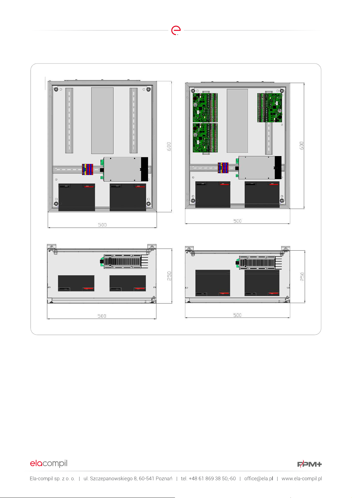
Strona 60 z 78
Page 62

Strona 61 z 78
19.3. FPM-6-YY-ZZ
Dimensions of the OBZ-FPMPLUS-6 housing are: 600x500x250. The housing can accommodate a maximum of six EPSCUS
modules. The housing can be fitted with an internal power supply, or adapted to work with an external power supply.
Page 63

Strona 62 z 78
Page 64
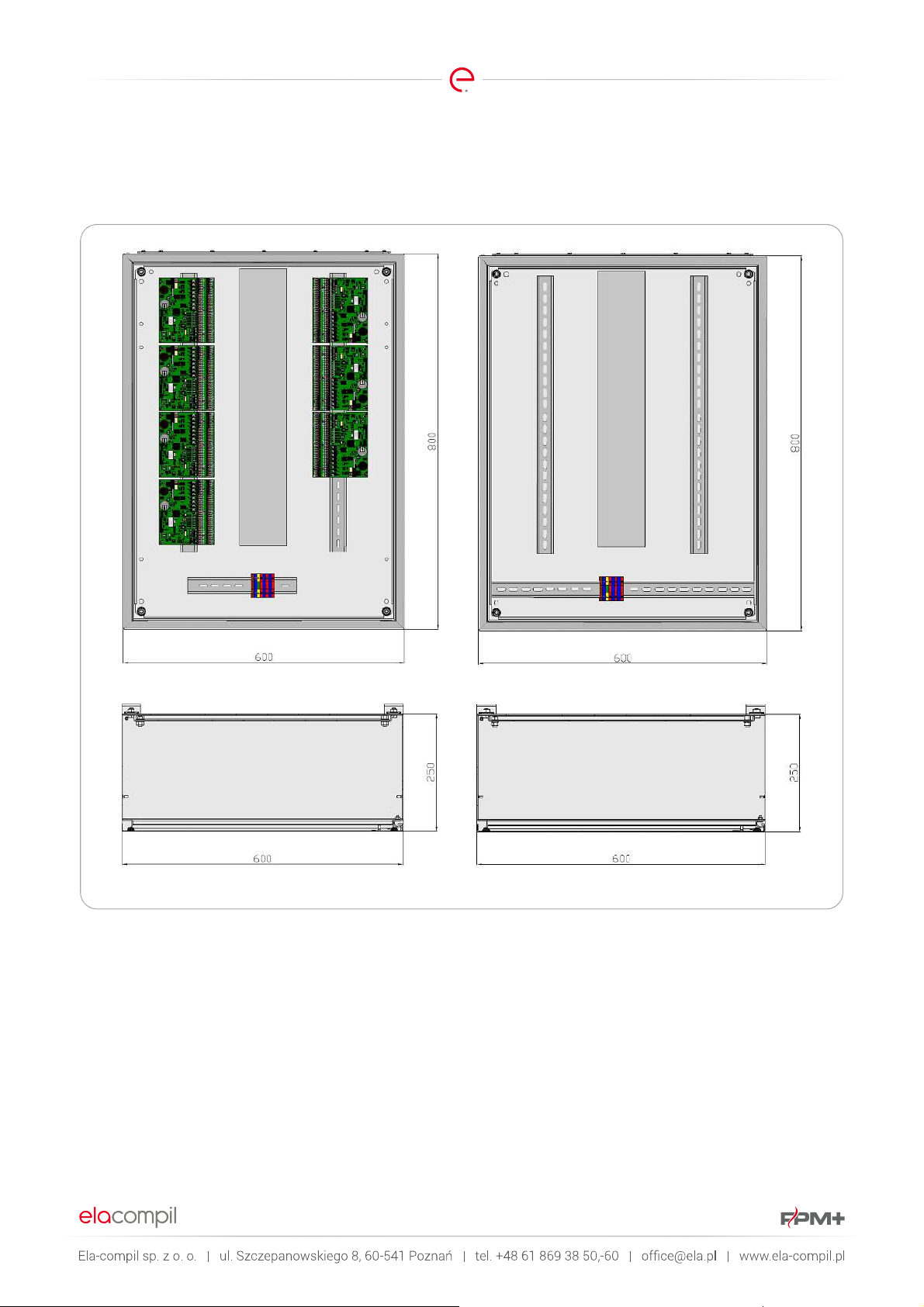
Strona 63 z 78
19.4. FPM-8-YY-ZZ
Dimensions of the OBZ-FPMPLUS-8 housing are: 800x600x210. The housing can accommodate a maximum of eight EPSCUS
modules. The housing can be fitted with an internal power supply, or adapted to work with an external power supply.
Page 65

Strona 64 z 78
Page 66

Strona 65 z 78
19.5. FPM-10-YY-ZZ
The OBZ-FPMPLUS-10 is the largest of FPM+ multiple-module unit housings, with the dimensions of 1000x600x250. The
housing can accommodate a maximum of ten EPSCUS modules. The housing can be fitted with an internal power supply, or
adapted to work with an external power supply.
Page 67

Strona 66 z 78
Page 68

Strona 67 z 78
20. APPENDIX C : FPM-U-X-X-X-X-X AND FPM-L-X-X-X-X HOUSING SPECIFICATIONS
FPM-U
FPM-U
FPM-U
FPM-U
FPM-U
FPM-U
FPM-U
FPM-U
FPM-U
FPM-U
FPM-U
FPM-U
FPM-U
FPM-U
FPM-U
FPM-U
FPM-U
FPM-U
FPM-U
FPM-U
FPM-U
FPM-U
FPM-U
FPM-U
FPM-L
FPM-L
FPM-L
FPM-L
CELLS
NO. OF
INSTALLATION
POWER SUPPLY
CURRENT [A]
BATTERY
CAPACITY [AH]
LAYOUT
CABLE TRAY
- 4 - 6 - 18 - A -
- 4 - 12 - 18 - A -
- 4 - 24 - 18 - A -
- 4 - 6 - 0 - A -
- 4 - 12 - 0 - A -
- 4 - 24 - 0 - A -
- 4 - 6 - 18 - B -
- 4 - 12 - 18 - B -
- 4 - 24 - 18 - B -
- 4 - 6 - 0 - B -
- 4 - 12 - 0 - B -
- 4 - 24 - 0 - B -
- 6 - 6 - 26 - A -
- 6 - 12 - 26 - A -
- 6 - 24 - 26 - A -
- 6 - 6 - 0 - A -
- 6 - 12 - 0 - A -
- 6 - 24 - 0 - A -
- 6 - 6 - 26 - B -
- 6 - 12 - 26 - B -
- 6 - 24 - 26 - B -
- 6 - 6 - 0 - B -
- 6 - 12 - 0 - B -
- 6 - 24 - 0 - B -
- 8 - 6 - 18 - A -
- 8 - 6 - 0 - A -
- 8 - 6 - 18 - B -
- 8 - 6 - 0 - B -
CABLE ENTRY
(TOP/BOTTOM)
G 600x600x250
G 600x600x250
G 600x600x250
D 600x600x250
D 600x600x250
D 600x600x250
G 600x600x250
G 600x600x250
G 600x600x250
D 600x600x250
D 600x600x250
D 600x600x250
G 800x600x300
G 800x600x300
G 800x600x300
D 800x600x300
D 800x600x300
D 800x600x300
G 800x600x300
G 800x600x300
G 800x600x300
D 800x600x300
D 800x600x300
D 800x600x300
G 600x500x250
D 600x500x250
G 600x500x250
D 600x500x250
W X D)
HOUSING
DIMENSIONS (H X
Page 69

The FPM
with 4 installation cells (FPM
supply with max. current 6A (FPM
without batteries (FPM
tray layout A (main tray in central location
FPM
bottom part of the housing (FPM
D).
The housing can be fitted with 6A, 12A or 24A
power supply; according to the selected
option, the respective field in the housing
symbol will change.
A single e.USP module or two e.LSK modules
can be installed in a single cell.
Dimensions of the h
600x600x250mm
21. APPENDIX D : FPM-U-X-X-X-X-X AND FPM-L-X-X-X-X HOUSINGS - DRAWINGS
21.1. FPM-U-4-6-0-A-D
Strona 68 z 78
-U-4-6-0-A-D is a universal housing
-U-4), a power
-U-4-6-0), with a cable
-U-4-6-0-A) and cable glands in the
-U-4-6-0-A-
-U-4-6),
ousing:
Power supply
-
Page 70
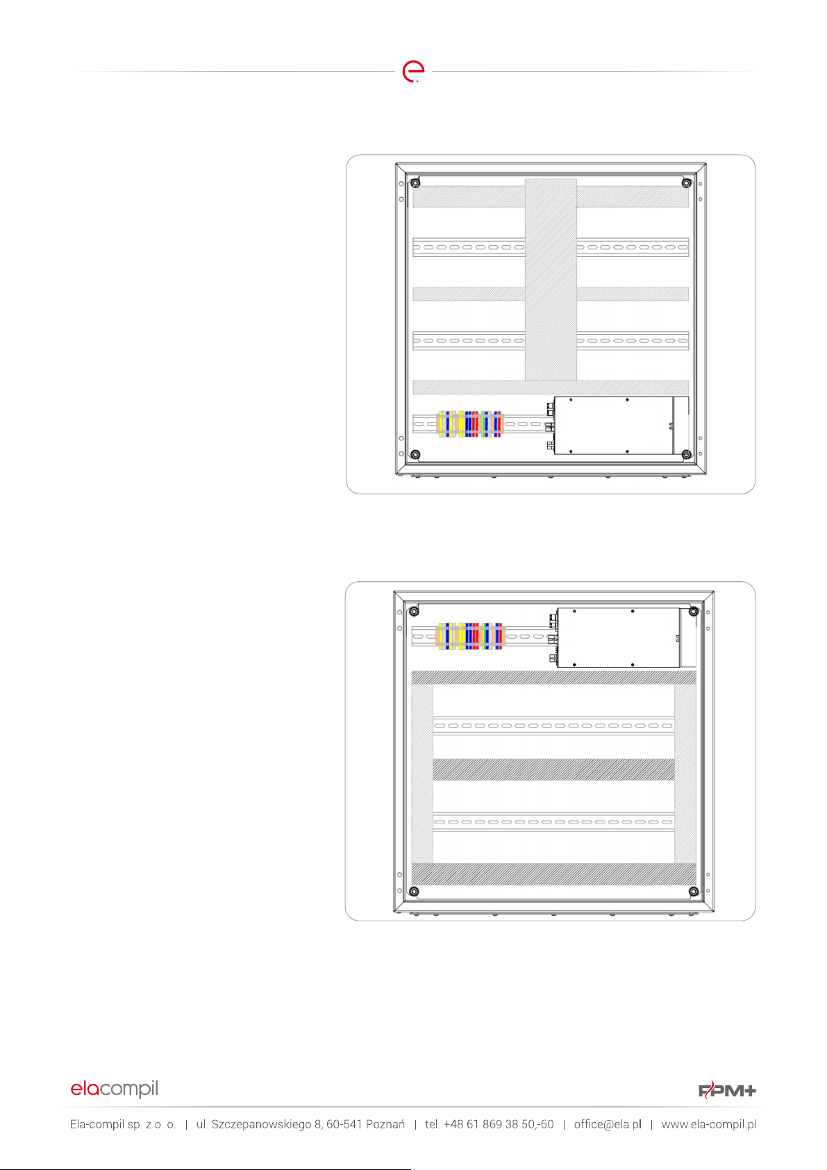
The FPM
with 4 installation cells (FPM
supply with max. current 6A (FPM
with 18Ah batteries (FPM
cable tray layout A (main tray in c
location
in the upper part of the housing (FPM
18
The housing can be fitted with 6A, 12A or
24A power supply; according to the selected
option, the respective field in the housing
symbol will change.
A
modules can be installed in a single cell.
Dimensions of the housing:
600x600x250mm
The FPM
with 4 installation cells (FPM
supply with max. current 6A
without batteries (FPM
tray layout B (trays around installation cells
FPM
bottom part of the housing (FPM
D).
The housing can be fitted with 6A, 12A or
24A power supply; ac
option, the respective field in the housing
symbol will change.
A single e.USP module or two e.LSK
modules can be installed in a single cell.
Dimensions of the housing:
600x600x250mm
21.2. FPM-U-4-6-18-A-G
Strona 69 z 78
-U-4-6-0-A-G is a universal housing
-U-4), a power
-U-4-6-18), with a
- FPM-U-4-6-18-A) and cable glands
-A-G).
single e.USP module or two e.LSK
21.3. FPM-U-4-6-0-B-D
-U-4-6),
entral
-U-4-6-
Power supply
-U-4-6-0-B-D is a universal housing
-U-4), a power
(FPM-U-4-6),
-U-4-6-0), with a cable
-U-4-6-0-B) and cable glands in the
-U-4-6-0-B-
cording to the selected
Power supply
-
Page 71

The FPM
with 4 installation cells (FPM
supply with max. current 6A (FPM
with 18Ah batteries (FPM
cable tray layout B (trays around installation
cells
the upper part
18
The housing can be fitted with 6A, 12A or
24A power supply; according to the selected
option, the respective field in the housing
symbol will change.
A single e.USP module or two e.LSK
modules can be installed in a single
Dimensions of the housing:
600x600x250mm
The FPM
with 6 installation cells (FPM
supply with max. current 6A (FPM
without batteries (FPM
tray lay
FPM
bottom part of the housing (FPM
D).
The housing can be fitted with 6A, 12A or
24A power supply; according to the selected
option, the respective field in the housing
sy
A single e.USP module or two e.LSK
modules can be installed in a single cell.
Dimensions of the housing:
800x600x250mm
21.4. FPM-U-4-6-18-B-G
Strona 70 z 78
-U-4-6-0-B-D is a universal housing
-U-4), a power
-U-4-6-18), with a
- FPM-U-4-6-18-B) and cable glands in
of the housing (FPM-U-4-6-
-B-G).
21.5. FPM-U-6-6-0-A-D
-U-4-6),
cell.
Power supply
-U-6-6-0-A-D is a universal housing
-U-4), a power
-U-6-6-0), with a cable
out A (main tray in central location -
-U-6-6-0-A) and cable glands in the
mbol will change.
Power supply
-U-6-6),
-U-6-6-0-A-
Page 72

The FPM
housing with 6 installation cells (FPM
power sup
6
with a cable tray layout A (main tray in
central location
glands in the upper part of the housing
(FPM
The housing can be fitted with 6A, 1
24A power supply; according to the selected
option, the respective field in the housing
symbol will change.
A single e.USP module or two e.LSK
modules can be installed in a single cell.
Dimensions of the housing:
800x600x250mm
The FPM
with 6 installation cells (FPM
supply with max. current 6A (FPM
without batteries (FPM
cable tray layout B (trays around installation
cells
the bottom part of the housing (FPM
0
The housing can be fitted with 6A, 12A or
24A power supply; according to the selected
option, the respective field in the housing
symbol will change.
A single e.USP module or two e.LSK
modules can be in
Dimensions of the housing:
800x600x250mm
21.6. FPM-U-6-6-26-A-G
Strona 71 z 78
-U-6-6-26-A-G is a universal
-U-6), a
ply with max. current 6A (FPM-U-
-6), with 26Ah batteries (FPM-U-6-6-26),
- FPM-U-6-6-26-A) and cable
-U-6-6-26-A-G).
2A or
Power supply
21.7. FPM-U-6-6-0-B-D
-U-6-6-0-B-D is a universal housing
-U-6), a power
-U-6-6-0), with a
- FPM-U-6-6-0-B) and cable glands in
-B-D).
stalled in a single cell.
Power supply
-U-6-6),
-U-6-6-
Page 73

The FPM
with 6 installation cells (FPM
supply with max. current 6A (FPM
with 26Ah batteries (FPM
cable tray layout B (trays around installation
cells
the upper part of the housing (FPM
26
The housing can be fitted with 6A, 12A or
24A power supply; according to the selected
option, the respect
symbol will change.
A single e.USP module or two e.LSK
modules can be installed in a single cell.
Dimensions of the housing:
800x600x250mm
The FPM
to e.LSK modules, capable
accommodating max. 8 modules (FPM
a power supply with max. current 6A (FPM
L
a cable tray layout A (main tray in central
location
in the bottom part of the housing (FPM
6
Dimensions of the housing:
600x500x250mm
21.8. FPM-U-6-6-26-B-G
Strona 72 z 78
-U-6-6-0-B-D is a universal housing
-U-6), a power
-U-6-6-26), with a
- FPM-U-6-6-26-B) and cable glands in
-B-G).
ive field in the housing
-U-6-6),
-U-6-6-
Power supply
21.9. FPM-L-8-6-0-A-D
-U-8-6-0-A-D is a housing dedicated
of
-L-8),
-8-6), without batteries (FPM-L-8-6-0), with
- FPM-L-8-6-0-A) and cable glands
-L-8-
-0-A-D).
Power supply
-
Page 74

The FPM
dedicated to e.LSK modules, capable of
accommodating max. 8 modules (FPM
a power supply with max. current 6A (FPM
L
with a cable tray layout A (main tray in
central location
glands in the upper part of the housing
(FPM
Dimensions of the housing:
600x500x250mm
The FPM
to e.LSK modules, capable of
accommodating max. 8 modules (FPM
a power supply with max. current 6A (FPM
L
a cable tray layout B (trays around
installation cells
glands in the bottom part of the housing
(FPM
Dimensions of the housing:
600x500x250mm
21.10. FPM-L-8-6-18-A-G
Strona 73 z 78
-U-8-6-18-A-D is a housing
-L-8),
-8-6), with 18Ah batteries (FPM-L-8-6-18),
- FPM-L-8-6-18-A) and cable
-L-8-6-18-A-G).
21.11. FPM-L-8-6-0-B-D
-
Power supply
-U-8-6-0-B-D is a housing dedicated
-L-8),
-8-6), without batteries (FPM-L-8-6-0), with
- FPM-L-8-6-0-B) and cable
-L-8-6-0-B-D).
Power supply
-
Page 75

The FPM
dedicated to e.LSK modules, capable of
accommodating max. 8 modules (FPM
a power su
L
with a cable tray layout B (trays around
installation cells
glands in the upper part of the housing
(FPM
Dimensions of the housing:
600x50
21.12. FPM-L-8-6-18-B-G
Strona 74 z 78
-U-8-6-18-A-D is a housing
-L-8),
pply with max. current 6A (FPM-
-8-6), with 18Ah batteries (FPM-L-8-6-18),
- FPM-L-8-6-18-B) and cable
-L-8-6-18-B-G).
0x250mm
Power supply
Page 76
Strona 75 z 78
ZPAS
WZ-
1951
-01-24-
011 600 650 1800
500
ZPAS
WZ-
1951
-01-23-
011 600 650 1800
600
ZPAS
WZ-
1951
-01-21-
011 800 850 1800
500
ZPAS
WZ-
1951
-01-20-
011 800 850 1800
600
ZPAS
WZ-
1951
-01-50-
011 600 650 2000
400
ZPAS
WZ-
1951
-01-12-
011 600 650 2000
500
ZPAS
WZ-
1951
-01-11-
011 600 650 2000
600
ZPAS
WZ-
1951
-01-10-
011 600 650 2000
800
ZPAS
WZ-
1951
-01-49-
011 800 850 2000
400
ZPAS
WZ-
1951
-01-09-
011 800 850
2000
500
ZPAS
WZ-
1951
-01-08-
011 800 850 2000
600
ZPAS
WZ-
1951
-01-07-
011 800 850 2000
800
22. APPENDIX E: CUSTOM HOUSINGS
On special order, control unit housings with different capacity or dimensions can be produced. The housings must meet the
isolation criteria (min. IP42). Housings can be used from the following ranges:
SWN WALL-MOUNTED CABINETS
MANUFACTURER
SYMBOL
HEIGHT
WIDTH
ZPAS WZ-2285-01-06-011 500 400 210
ZPAS WZ-2285-01-09-011 500 400 300
ZPAS WZ-2285-01-10-011 500 500 210
ZPAS WZ-2285-01-07-011 600 400 250
ZPAS WZ-2285-01-12-011 600 500 250
ZPAS WZ-2285-01-13-011 600 500 300
ZPAS WZ-2285-01-15-011 600 600 250
ZPAS WZ-2285-01-16-011 800 600 250
ZPAS WZ-2285-01-18-011 800 600 300
ZPAS WZ-2285-01-19-011 800 800 300
ZPAS WZ-2285-01-17-011 1000 600 250
ZPAS WZ-2285-01-20-011 1000 800 300
SZE2 CABINETS – WITH SINGLE LEAF DOOR
WIDTH
MANUFACTUR
ER
SYMBOL
With integrated
shielding
With external
shielding
HEIGHT
DEPTH
DEPTH
Page 77

RITTAL
1045.500
400 500 210
RITTAL
1090.500
600 1000
250
RITTAL
1101.020
400 400 250
SZE2 CABINETS – WITH DOUBLE LEAF DOOR
WIDTH
MANUFACTU
RER
SYMBOL
With integrated
shielding
With external
shielding
HEIGHT
ZPAS WZ-1951-01-15-011 1200 1250 1800 500
ZPAS WZ-1951-01-14-011 1200 1250 1800 600
ZPAS WZ-1951-01-06-011 1000 1050 2000 500
ZPAS WZ-1951-01-05-011 1000 1050 2000 600
ZPAS WZ-1951-01-04-011 1200 1250 2000 500
ZPAS WZ-1951-01-03-011 1200 1250 2000 600
ZPAS WZ-1951-01-02-011 1200 1250 2000 800
KOMPAKT AE CONTROL HOUSINGS
Strona 76 z 78
DEPTH
MANUFACTURER
SYMBOL
WIDTH
HEIGHT
DEPTH
RITTAL 1037.500 400 800 300
RITTAL 1050.500 500 500 210
RITTAL 1350.500 500 500 300
RITTAL 1057.500 500 700 250
RITTAL 1039.500 600 380 210
RITTAL 1339.500 600 380 350
RITTAL 1060.500 600 600 210
RITTAL 1054.500 600 600 250
RITTAL 1360.500 600 600 350
RITTAL 1076.500 600 760 210
RITTAL 1376.500 600 760 350
RITTAL 1058.500 600 800 250
RITTAL 1260.500 600 1200 300
RITTAL 1077.500 760 760 210
RITTAL 1073.500 760 760 300
RITTAL 1055.500 800 600 300
RITTAL 1180.500 800 1000 300
RITTAL 1280.500 800 1200 300
RITTAL 1100.500 1000 760 210
RITTAL 1130.500 1000 760 300
RITTAL 1110.500 1000 1000 300
RITTAL 1213.500 1000 1200 300
RITTAL 1114.500 1000 1400 300
RITTAL 1101.030 400 650 250
RITTAL 1101.040 650 650 250
Page 78

KOMPAKT AE CONTROL HOUSINGS, STAINLESS STEEL
Strona 77 z 78
MANUFACTURER
RITTAL 1009.600 600 380 210
RITTAL 1015.600 400 500 210
RITTAL 1007.600 500 500 210
RITTAL 1013.600 500 500 300
RITTAL 1008.600 380 600 210
RITTAL 1010.600 600 600 210
RITTAL 1010.500 600 600 210
RITTAL 1012.600 600 760 210
RITTAL 1014.600 760 760 300
RITTAL 1016.600 800 1000 300
RITTAL 1017.600 800 1200 300
RITTAL 1018.600 1000 1000 300
RITTAL 1019.600 1000 1200 300
RITTAL 1019.500 1000 1200 300
RITTAL 1101.120 400 400 250
RITTAL 1101.130 400 650 250
RITTAL 1101.140 650 650 250
SYMBOL
WIDTH
HEIGHT
DEPTH
KOMPAKT RITTAL CM SYSTEM HOUSINGS
Manufacturer
RITTAL 5110.500 600 800 400
RITTAL 5111.500 600 1000 400
RITTAL 5112.500 600 1200 300
RITTAL 5113.500 600 1200 400
RITTAL 5114.500 800 1000 300
RITTAL 5115.500 800 1000 400
RITTAL 5116.500 800 1200 300
RITTAL 5117.500 800 1200 400
RITTAL 5118.500 1000 1000 300
RITTAL 5119.500 1000 1200 300
RITTAL 5120.500 1000 1200 400
RITTAL 5121.500 1000 1400 300
RITTAL 5122.500 1000 1400 400
RITTAL 5123.500 1200 1200 400
Symbol
Width
Height
Depth
Page 79

MANUFACTUR
ER
RITTAL
5850.500
600 1600
400
RIT
TAL 5851.500
600 1800
500
RITTAL
5852.500
800 1800
500
RITTAL
5853.500
800 2000
600
RITTAL
5854.500
1000
1800
400
RITTAL
5855.500
1200
2000
500
SYSTEM CABINET, SINGLE, SE 8
Strona 78 z 78
Symbol
Manufacturer
RITTAL 5830.500 600 1800 400
RITTAL 5831.500 800 1800 400
RITTAL 5832.500 800 2000 400
RITTAL 5833.500 800 2000 500
RITTAL 5834.500 800 2000 600
RITTAL 5840.500 1000 1800 400
RITTAL 5841.500 1200 1800 400
RITTAL 5842.500 1600 1800 400
RITTAL 5843.500 1200 2000 400
RITTAL 5844.500 1200 2000 500
RITTAL 5845.500 1200 2000 600
RITTAL 5846.500 1800 2000 500
Width
Height
SYSTEM CABINET, SINGLE, SE 8 - STAINLESS STEEL
SYMBOL
WIDTH
HEIGHT
DEPTH
Depth
 Loading...