

Page 1
Integrator Series
MULTI-CHANNEL POWER AMPLIFIERS
OPERATING INSTRUCTIONS
IS-AMP8100
IS-AMP1275
IS-AMP1650
Page 2
RISK OF ELECTRIC SHOCK
DO NOT OPEN
RISQUE DE CHOQUE ÉLECTRIQUE
N'OUVREZ PAS
Important Safety Instructions
CAUTION: To reduce the risk of electric shock, do not remove cover (or
back).
No user-serviceable parts inside. Refer servicing to qualified service
personnel.
APPLICABLE FOR USA, CANADA OR
WHERE APPROVED FOR USAGE
CAUTION: TO PREVENT ELECTRIC
SHOCK, MATCH WIDE BLADE PLUG TO
WIDE SLOT, INSERT FULLY.
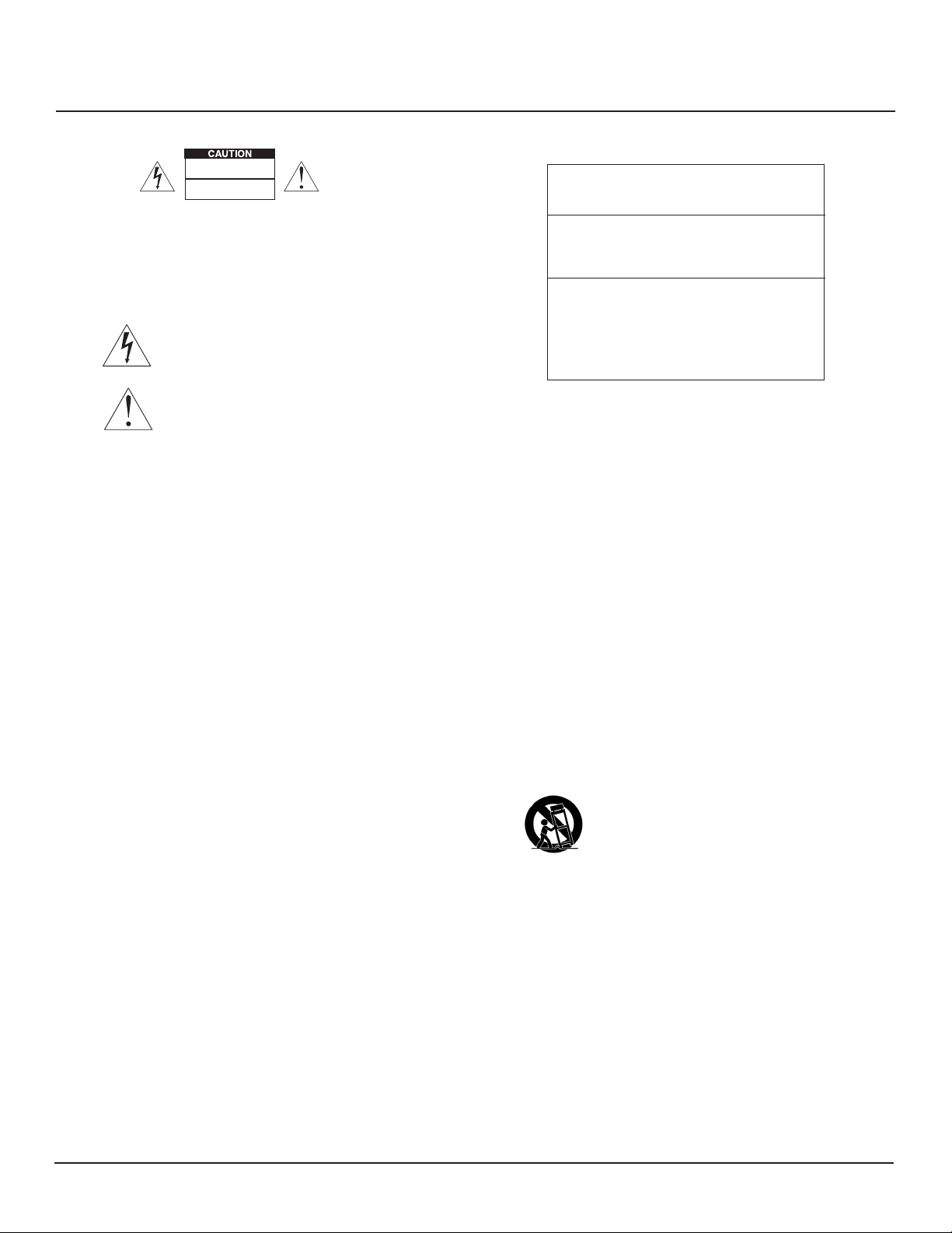
• Explanation of Graphical Symbols
ATTENTION: POUR EVITER LES CHOCS
ELECTRIQUES, INTRODUIRE LA LAME
The lightning flash with arrowhead symbol, within an equilateral triangle,
is intended to alert you to the presence of uninsulated “dangerous
voltage” within the product’s enclosure that may be of sufficient magnitude to constitute a risk of electric shock to persons.
The exclamation point within an equilateral triangle is intended to alert
you to the presence of important operating and maintenance (servicing) instructions in the literature accompanying the product.
1. Read these instructions.
2. Keep these instructions.
3. Heed all warnings.
4. Follow all instructions.
5. Do not use this apparatus near water.
6. Clean only with a dry cloth.
7. Do not block any ventilation openings. Install in accordance with the manufacturer’s instructions.
8. Do not install near any heat sources such as radiators, heat registers, stoves, or other apparatus (including amplifiers) that produce heat.
9. Do not defeat the safety purpose of the polarized or grounding-type plug. A polarized plug has two blades with one wider than the other. A
grounding-type plug has two blades and a third grounding prong. The wide blade or the third prong are provided for your safety. If the provided plug does not fit into your outlet, consult an electrician for replacement of the obsolete outlet.
10. Protect the power cord from being walked on or pinched particularly at plugs, convenience receptacles, and the point where they exit from
the apparatus.
11. Only use attachments/accessories specified by the manufacturer.
12. Use only with the cart, stand, tripod, bracket, or table specified by the manufacturer, or sold with the apparatus. When a cart is used, use caution when moving the cart/apparatus combination to avoid injury from tip-over.
LA PLUS LARGE DE LA FICHE DANS LA
BORNE CORRESPONDANTE DE LA PRISE
ET POUSSER JUSQU AU FOND.
PORTABLE CART WARNING
13. Unplug this apparatus during lightning storms or when unused for long periods of time.
14. Refer all servicing to qualified service personnel. Servicing is required when the apparatus has been damaged in any way, such as power-supply cord or plug is damaged, liquid has been spilled or objects have fallen into the apparatus, the apparatus has been exposed to rain or moisture, does not operate normally, or has been dropped.
15. The apparatus shall not be exposed to dripping or splashing and that no objects filled with liquids, such as vases, shall be placed on the apparatus.
16. CAUTION: Servicing instructions are for use by qualified service personnel only. To reduce the risk of electric shock, do not perform any servicing
other than that contained in the operating instructions unless you are qualified to do so.
17. WARNING: To reduce the risk of fire or electric shock, do not expose this apparatus to rain or moisture.
MULTI-CHANNEL POWER AMPLIFIER | www.elac.com | Page 2
Page 3

Table of Contents
Important Safety Instructions ................................................................................................................................. 2
Table of Contents....................................................................................................................................................3
Introduction ............................................................................................................................................................. 4
Front Panel Features ............................................................................................................................................... 5
Rear Panel Features ...............................................................................................................................................5
Speaker Connections ............................................................................................................................................7
12 Volt Trigger .........................................................................................................................................................8
Ventilation ...............................................................................................................................................................8
Specications .........................................................................................................................................................9
Amplier GUI Control Panel ................................................................................................................................. 10
Warranty ................................................................................................................................................................ 14
MULTI-CHANNEL POWER AMPLIFIER | www.elac.com | Page 3
Page 4

Introduction
Congratulations and thank you for purchasing the Integrator Series multi-channel power
amplier!
Since the time we started in 1926, ELAC has always striven to achieve the very best!
The Integrator Series multi-channel power amplier feature a combination of performance,
exibility and control to provide high value and great sound in different amplication
arrangement.
The Integrator Series IS-AMP8100, IS-AMP1275 and IS-AMP1650 are DSP can be congured in
two speaker output modes: stereo mode and bridged mode.
The multi-channel power amplier series feature network control.
All models have many DSP tools including level controls, EQ’s, high and low pass lters,
limiters to provide exibility for different ampplications.
Access to the DSP settings is accomplished via web GUI interface.
Please read and follow the instructions in this guide to assist in proper installation, connection
and use of your ELAC multi-channel power amplier.
MULTI-CHANNEL POWER AMPLIFIER | www.elac.com | Page 4
Page 5
Front and Rear Panel Features
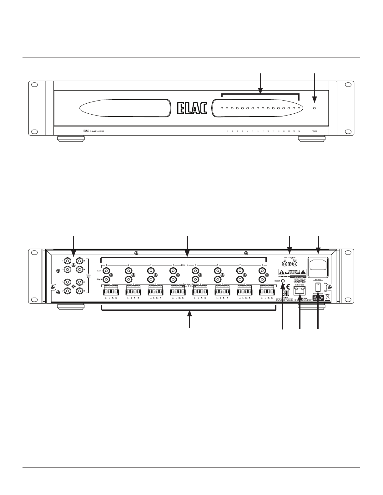
Figure 1 IS-AMP1650 FRONT Panel Features (shown for reference)
1. POWER LED - Shows the amplier unit is ON.
2. STATUS LED - Shows the status of the amplier unit:
Blue - shows the signal is present
Short red - shows the signal is clipping
Solid red - shows the amplier unit is in protection mode
12
43
10
Figure 2 IS-AMP1650 Rear Panel Features (shown for reference)
3. LINE OUT - These are assignable outputs via the web GUI interface.
4. LINE IN - Use these RCA connectors to input audio signal into the power amplier.
Depending on the model, the amplier have 8, 12 or 16 line inputs.
The Line Inputs are assigned to the corresponding Speaker Outputs by default.
5. 12V TRIGGER - Use this connection to ON/OFF control the amplier unit (5 ... 24V DC).
5
9
6
8 7
6. AC MAINS - After all other connections have been made and conrmed, using the
included power cord, connect the AC Mains on the amplier to an AC outlet.
MULTI-CHANNEL POWER AMPLIFIER | www.elac.com | Page 5
Page 6

Front and Rear Panel Features (cont.)
7. POWER SWITCH - Used to turn ON/OFF the amplier.
8. ETHERNET - Using an Ethernet cable, connect the Ethernet port on the amplier to local
network (LAN). The Ethernet port is used for setting up the amplier through it’s web GUI
and for 3rd party control.
9. RESET - Use this button to reset the IP settings. The reset button on the rear panel of the
amplier will reset the IP settings only. You can reset the other functions of the amplier
via Web interface only (see GUI Controls Dened).
10. SPEAKER OUT - Using 12AWG (max) speaker wire, connect the speakers outputs on the
amplier to the appropriate speaker terminals. Before connecting the speaker wires,
twist the ends of the speaker wire so there are no strays that can cause shorts. See
section: Speaker Connections for additional information.
MULTI-CHANNEL POWER AMPLIFIER | www.elac.com | Page 6
Page 7
Speaker Connections
Speaker Connections
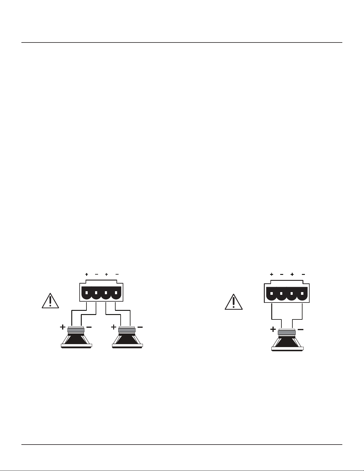
The 4 pin connector plugs allows easy connection of two speakers for single ended connection or one speaker for bridged connection.
1. Use 12AWG (max) 2-conductor stranded speaker wire for speaker connection plugs.
2. Strip approximately 1/4 to 1/2 of an inch off the ends and twist the strands together so
there are no loose ends that can cause shorts.
3. On the amplier rear panel, insert one end of each striped speaker wires into the provid-
ed plugs and tighten the screws. Ensure that all speaker wires are rmly attached to the
plugs.
4. Match the polarity markings on the rear panel of the amplier unit with the polarity of the
speakers. If the wiring is incorrect then the peakers will be out-of-phase, with a noticable
decrease of in the bass frequencies and and sound performance.
5. Connect the speaker wires to the appropriate + and - terminals on the speakers. Conrm
connection and polarity.
For single ended speaker connection (Figure 3) the speaker impedance sholud be 4 ohm or
8 ohm.
For bridges speaker connection (Figure 4) the speaker impedance sholud be 8 ohm.
L RR
L
4 or 8 ohm 4 or 8 ohm
Figure 3 Single ended speaker connection
Figure 4 Bridged speaker connection
L RR
L
8 ohm only
NOTE: If the Speaker Out senses a short, the amplier will enter protect mode and ‘Fault’ will
appear in the amplier web page and app. In “Fault” mode, the audio amp will be shut
down, but the logic and control will remain on.
To reset the amp, power cycle the amplier: unplug the amplier from the wall jack
for minimum 30 seconds and then plug it back in. If the amp does not return to normal
operation, please contact ELAC at 714.252.8843 or at [email protected].
MULTI-CHANNEL POWER AMPLIFIER | www.elac.com | Page 7
Page 8
12 Volt Trigger & Ventilation
12V Trigger IN
When a voltage between + 5V DC and +24V DC is sensed at the trigger input the amplier is
turned ON.
12V Trigger OUT
The output trigger has a 12V voltage and 10 mA current.
Ventilation
The multi-channel power amplier series IS-AMP8100, IS-AMP1275 and IS-AMP1650 require
plenty of good ventilation to properly cool and work within the design parameters.
There are thermal sensors to protest the amplier from overheating. If overheat occurs, the
amplier is entering in compression mode which means, less output power.
Further more, in some extreme overheating cases, the amplier is protecting it self by turning
OFF. If this occurs often, identify the cause and take corrective actions:
• do not install the amplier in a sealed location with poor ventilation
• install a fan in the rack
• make sure the amplier(s) are not overloaded with speakers impedances below the
recommended minimum impedance
• ensure there are no short circuits in the speaker cables or speakers
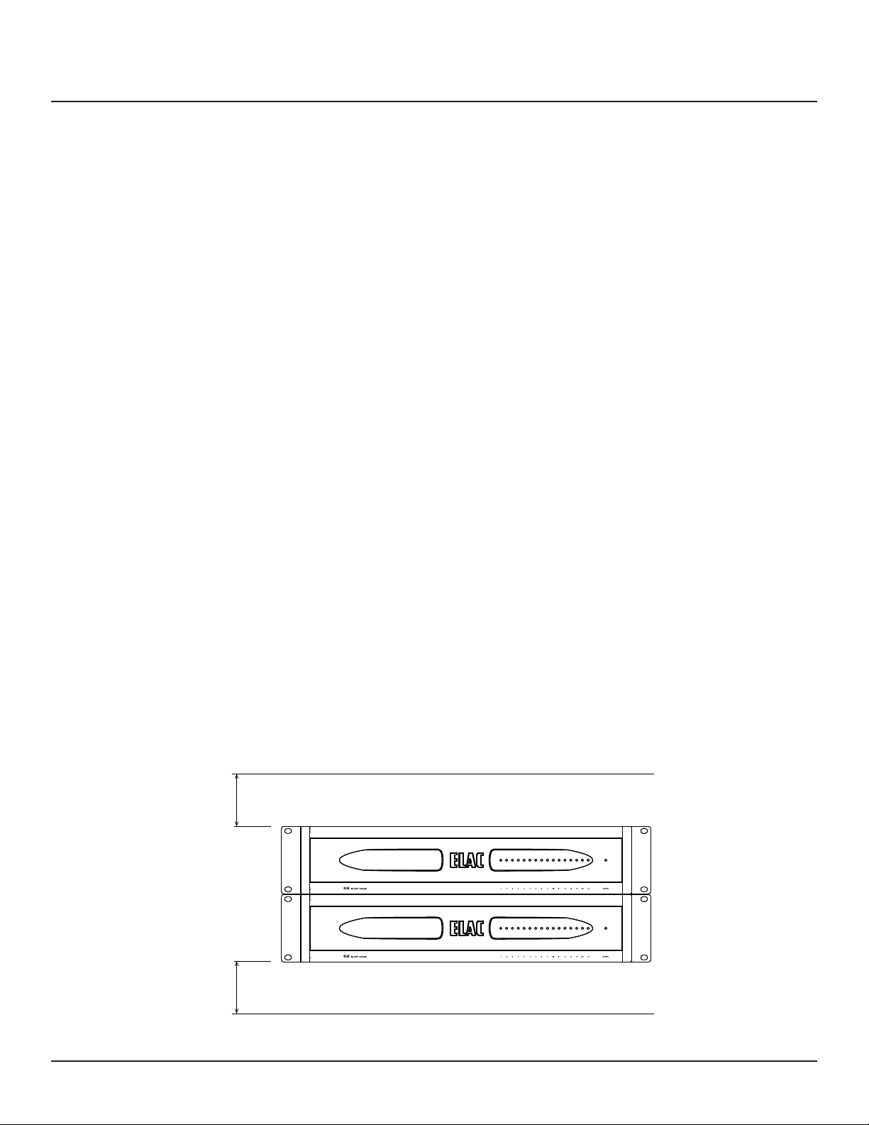
NOTE: Please, be advised that no more than 2 ampliers can be stacked together without a
1U rack space or more between them.
Ideal spacing above and below each stack of 4 ampliers or individual amplier is
shown in Figure 5.
1U
1U
Figure 5 Spacing for ampliers stacked mount
MULTI-CHANNEL POWER AMPLIFIER | www.elac.com | Page 8
Page 9

Specications
Model IS-AMP8100 IS-AMP1275 IS-AMP1650
Number of channels 8 12 16
Zones 4 6 8
Power Output/channel
All channels driven
Bridged Power Output/
Mono mode
Input Sensitivity 775 mV 775 mV 775 mV
Maximum Input Voltage 4V 4V 4V
Input Impedance 20 Kohm 20 Kohm 20 Kohm
Crosstalk -65 dB at 1KHz -65 dB at 1KHz -65 dB at 1KHz
S/N Ratio 95 dBA 95 dBA 95 dBA
Speaker Output
Frequency Response
Distorsion (stereo output) 0.1% THD+N 1kHz
Distorsion (bridged) 0.1% THD+N 1kHz
AUTO ON
(Audio Sense Sensitivity)
12Volt Trigger Input 5V ... 24V 5V ... 24V 5V ... 24V
75W RMS at 8 ohm
75W RMS at 4 ohm
150W RMS at
8 ohm
20 Hz to 20 KHz 20 Hz to 20 KHz 20 Hz to 20 KHz
rated power
rated power
1mV ... 10mV
(adjustable)
75W RMS at 8 ohm
75W RMS at 4 ohm
150W RMS at
8 ohm
0.1% THD+N 1kHz
rated power
0.1% THD+N 1kHz
rated power
1mV ... 10mV
(adjustable)
50W RMS at 8 ohm
50W RMS at 4 ohm
100W RMS at
8 ohm
0.1% THD+N 1kHz
rated power
0.1% THD+N 1kHz
rated power
1mV ... 10mV
(adjustable)
12Volt Trigger Output 12V DC : 10mA 12V DC : 10mA 12V DC : 10mA
Line Inputs 8 12 16
Speaker Outputs 8 12 16
Line Outputs 8 8 8
Line Output
Frequency Response
Line Output 1.7V at 10 Kohm 1.7V at 10 Kohm 1.7V at 10 Kohm
Master Power Switch Yes Yes Yes
Ethernet Yes Yes Yes
Gain Control Yes Yes Yes
Bridged Switch
(Mono/Stereo)
Power Mode Switch Via Web Interface Via Web Interface Via Web Interface
Amplier Dimensions
(WxHxD) [inch/cm]
Amplier Weight [lb/kg] 16.32/7.4 18.96/8.6 20.4/9.25
20 Hz to 20 KHz 20 Hz to 20 KHz 20 Hz to 20 KHz
Via Web Interface Via Web Interface Via Web Interface
17.0x3.9x14.9/
43.18x9.84x37.8
17.0x3.9x14.9/
43.18x9.84x37.8
17.0x3.9x14.9/
43.18x9.84x37.8
MULTI-CHANNEL POWER AMPLIFIER | www.elac.com | Page 9
Page 10

Amplier GUI Control Panel
Accessing amplier GUI Control Panel
Open a Web browser.
In the Web browser address bar type in the IP address of the amplier and hit enter.
GUI Controls Dened
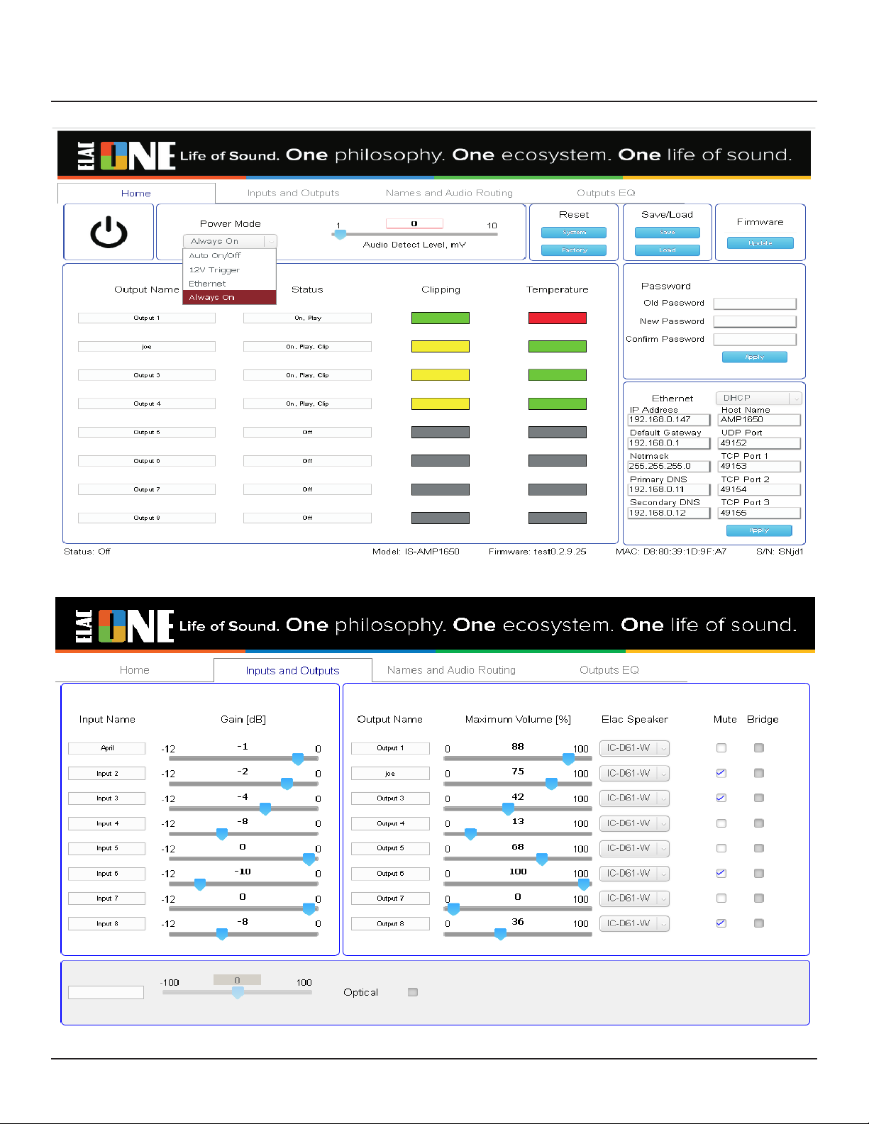
The amplier GUI control panel Home page is shown in Figure 6.
Most of the GUI controls are self explanatory, but some of the controls are described in
detail, below.
Power - Use this control to turn On/Off the amplier.
Power Mode - Use this control to select the power ON/OF mode of the amplier:
• Auto On/Off - The amplier is detecting the audio signal and it is turning on/off
automatically. If there is no audio for aprox. 20 min. the amplier is turning Off.
• Audio Detect Level - Alows you to select the sensitivity (in mV) of the Auto On/Off mode.
• 12V Trigger - Requires 12V (5 ... 24V DC) control connected to the amplier. In this mode
the On/Off commands from Ethernet will not work.
• Ethernet - Use this mode for home automatization audio system.
• Always On - In this mode the amplier never turns Off.
Reset - There are two reset modes:
• System - Use this reset mode to restart the amplier without the need to cycling the
power.
• Factory - In this reset mode you can reset he amplier all the settings, except the IP
settings. The IP settings reset can be done only from the RESET button at the rear panel of
the amplier.
Save/Load - Use these controls to save and load a conguration of the amplier.
• Save - Use this control to save your amplier conguration settings.
• Load - Use this control to load the amplier conguration settings from a saved le.
Firmware Update - Allows you to update the amplier rmware. Firmware update will also
restart the amplier.
Password - Use these elds to enter the amplier password.
Ethernet - These elds are used to set up the IP settings for the amplier.
MULTI-CHANNEL POWER AMPLIFIER | www.elac.com | Page 10
Page 11
Amplier GUI Control Panel (cont.)
Figure 6 Amplier GUI Control Panel - Home Page
Figure 7 Amplier GUI Control Panel - Inputs and Outputs Page
MULTI-CHANNEL POWER AMPLIFIER | www.elac.com | Page 11
Page 12

Amplier GUI Control Panel (cont.)
GUI Controls Dened (cont.)
The amplier GUI control panel Inputs and Outputs page is shown in Figure 7.
Input Name - In these elds you can see the input name for each input.
Gain [dB] - Use this control to set the gain of each input individualy.
Output name - In these elds you can see the output name for each output.
Volume - Use these controls to set the volume of each output individualy.
Elac Speaker - Used this control to select the Elac Speaker model or custom speaker which is
connected to the amplier.
Mute - Alows you to mute any output individualy.
Bridge - Use this control to put the speaker outputs in bridge mode.
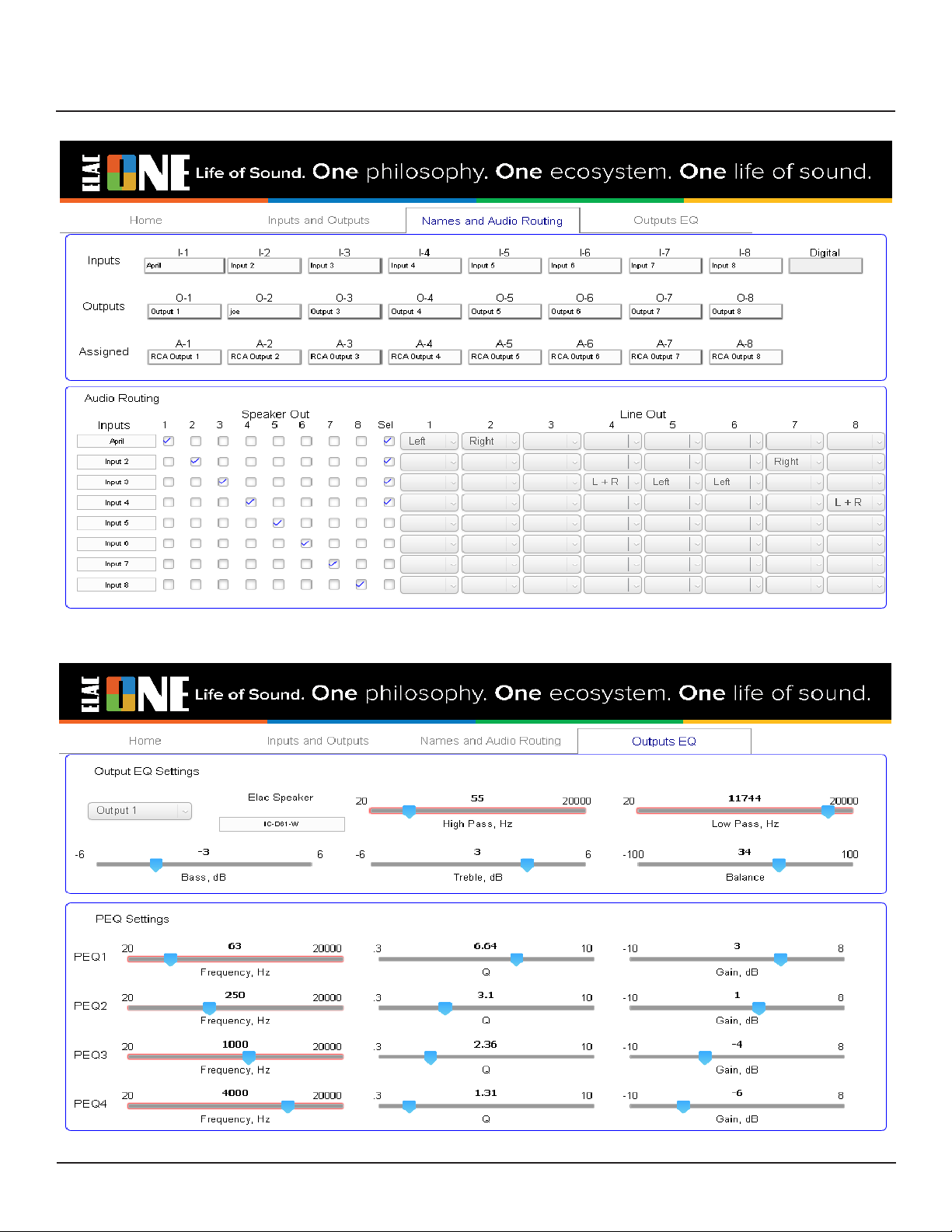
The amplier GUI control panel Names and Audio Routing page is shown in Figure 8.
Inputs - Use these elds to enter the input name for each input.
Outputs - Use these elds to enter the input name for each input.
Assigned - Use these elds to enter the RCA outputs name of individualy.
Audio Routing - Use these leds to select which input you want to be connected to RCA
output.
The amplier GUI control panel Outputs EQ page is shown in Figure 9.
Output Settings - Use these controls to select/change your EQ settings for the outputs.
PEQ Settings - Use these controls to select/change your parametric EQ settings (frequency,
Q and gain) for the outputs.
MULTI-CHANNEL POWER AMPLIFIER | www.elac.com | Page 12
Page 13
Amplier GUI Control Panel (cont.)
Figure 8 Amplier GUI Control Panel - Names and Audio Routing Page
Figure 9 Amplier GUI Control Panel - Outputs EQ Page
MULTI-CHANNEL POWER AMPLIFIER | www.elac.com | Page 13
Page 14

ELAC Americas Inc.
North America Limited Liability Warranty
Ampliers
ELAC Americas Inc. warrants to the original purchaser that this product be free from defects and or
workmanship for a period of 1 (One) year from the original date of purchase. During this time period,
repair or replacement of parts will be free of charge to the original owner (see limitations below).
Shipping to and return from the repair center will be the responsibility of the original purchaser.
Limitations
• Warranty begins on the date of original purchase from an authorized ELAC Americas Inc. dealer.
• Product is warranted only if used in home applications. Commercial use of this product is not
warranted
• Product has bee modied or altered in any way will not be warranted.
• Product that has been abused or subjected to faulty equipment will not be warranted.
• Products with defaced or removed serial numbers will not be warranted.
If Service is Required
In the event that service is required, please contact ELAC America at 714.252.8843 or at
[email protected] to arrange for service or replacement. You will be responsible to provide proof
of purchase (Copy or original sales receipt). Shipping to and from our repair center will be the
responsibility of the original purchaser.
Warranty Outside of North America
This warranty applies to products purchased in the United States and Canada. For Warranty
information claims outside of North America, please contact the local dealer/distributor in th country
of purchase.
TRADEMARK INFORMATION
The Bluetooth® word mark and logos are registered trademarks owned by the Bluetooth SIG, Inc.
and any use of such marks by ELAC Americas is under license.
Dolby, Dolby Audio and the double-D symbol are Trademarks of Dolby Laboratories.
App Store is a service mark of Apple Inc., registered in the U.S. and other countries.
Google Play and the Google Play logo are trademarks of Google Inc.
All other Trademarks and logos are property of their respective companies.
ELAC Americas Inc. • 11145 Knott Ave. Suites E & F • Cypress, CA 90603 • USA
714.252.8843 • elac.com
ELAC Electroacustic GmbH • Fraunhoferstraße 16 • 24118 Kiel • Germany
+49 (431) 64 77 4-0 • elac.com
©2019 ELAC AMERICAS Inc.
MULTI-CHANNEL POWER AMPLIFIER | www.elac.com | Page 19
 Loading...