

eLab Peers eBOT ARM User Manual
User Manual
V1.0

© eLab Peers 2017
All rights reserved.
V1.0 – October 2017
Part I Servo Calibration
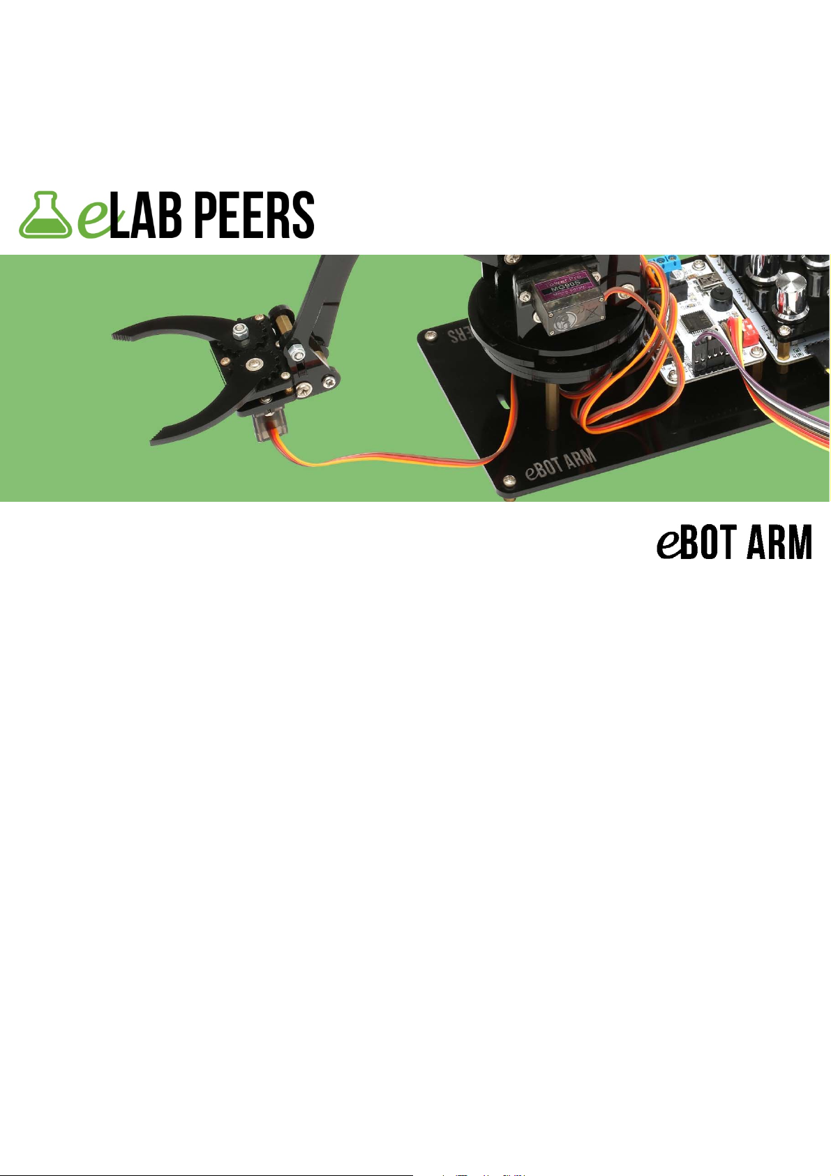
1. Take a servo.
2. Pick a servo horn. Place it to output spline of the servo. Turn the servo horn
anti-clockwise until it gets stuck.
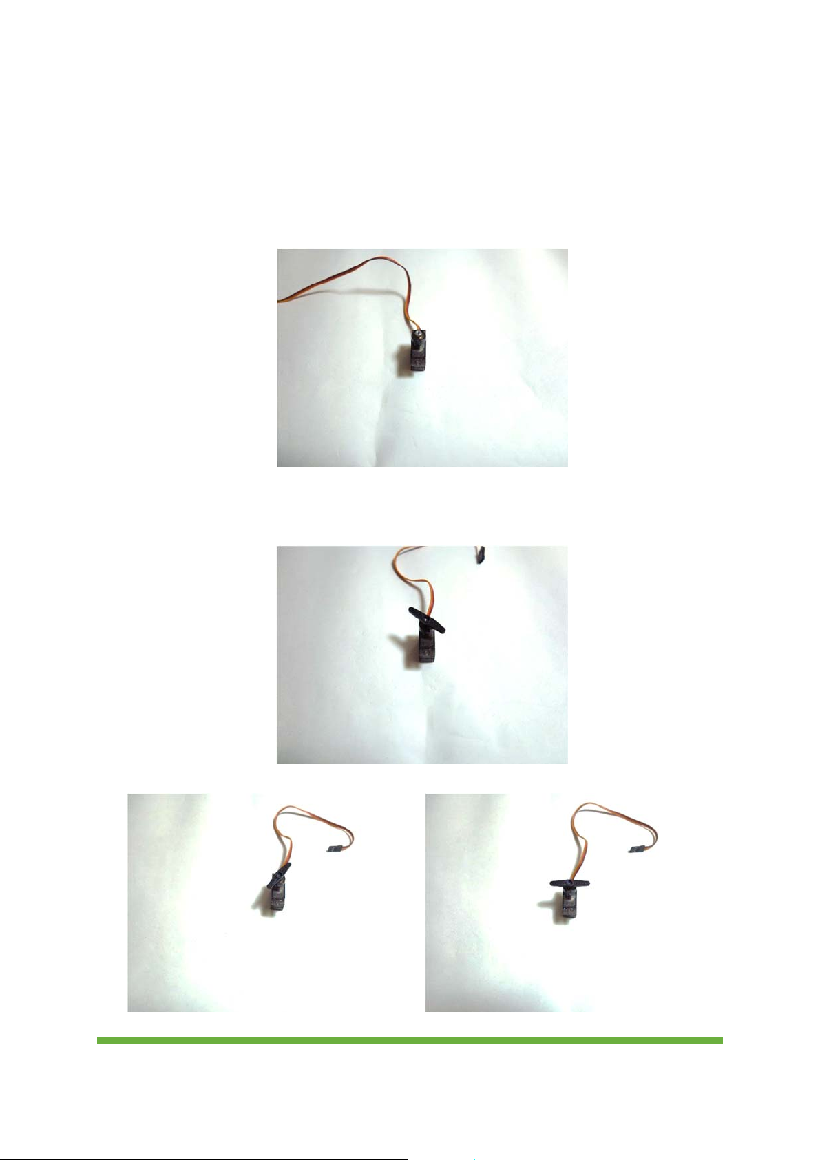
3. Take out the horn and place it to output spline again horizontally.
www.eLabpeers.com Page 3
4. Turn the horn again clockwise until the horn is in vertical direction. The output
spline is 90 degree approximately.
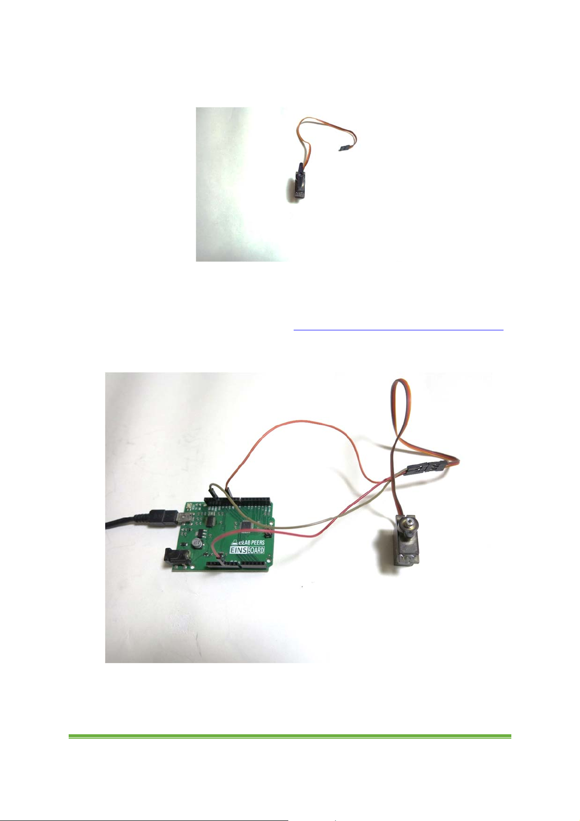
5. We can also calibrate the servos with Einsboard/Arduino compatible board.
Connect brown wire to GND on Einsboard, red to 5V and orange to digital pin 10.
Download Code for Servo Calibration from http://www.elabpeers.com/ebot-arm.html
and upload it to Einsboard. (Refer to Part VI Einsboard if there is any problem) Do the
same step for all servos.
6. There is another method of doing calibration. Connect servo to 8-Servo Controller
and adjust the servo via the software. (Please turn to Part III 8-Servo Controller for
details)
www.eLabpeers.com Page 4
Part II Assembly
A. Base
Please read through the instruction before start.
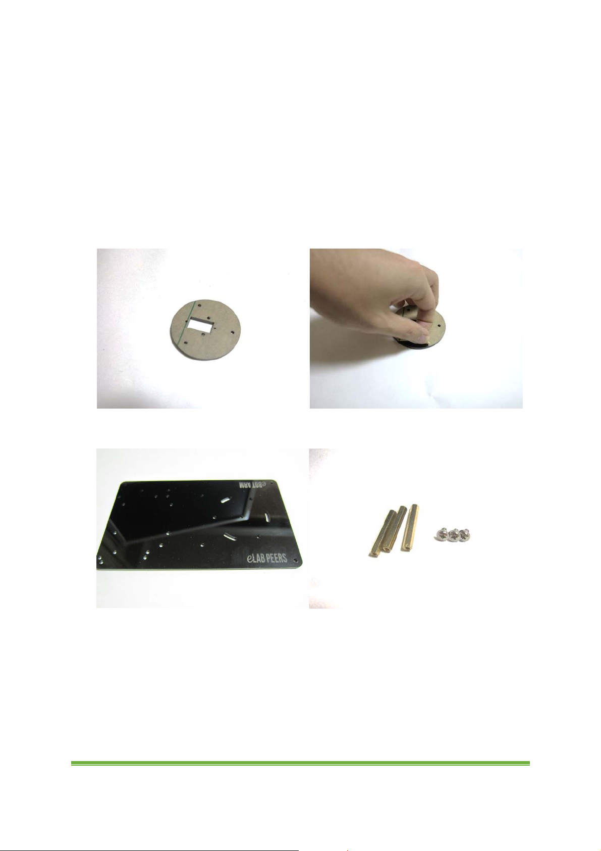
1. Tear off the paper layer on all acrylic parts.
2. Prepare a base, 3 x 30mm metal standoff and 3 x M3 truss head 5mm screws.
www.eLabpeers.com Page 5
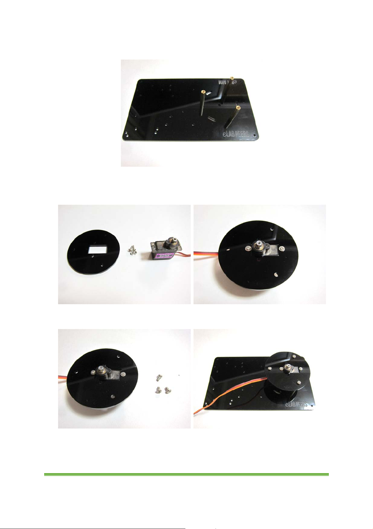
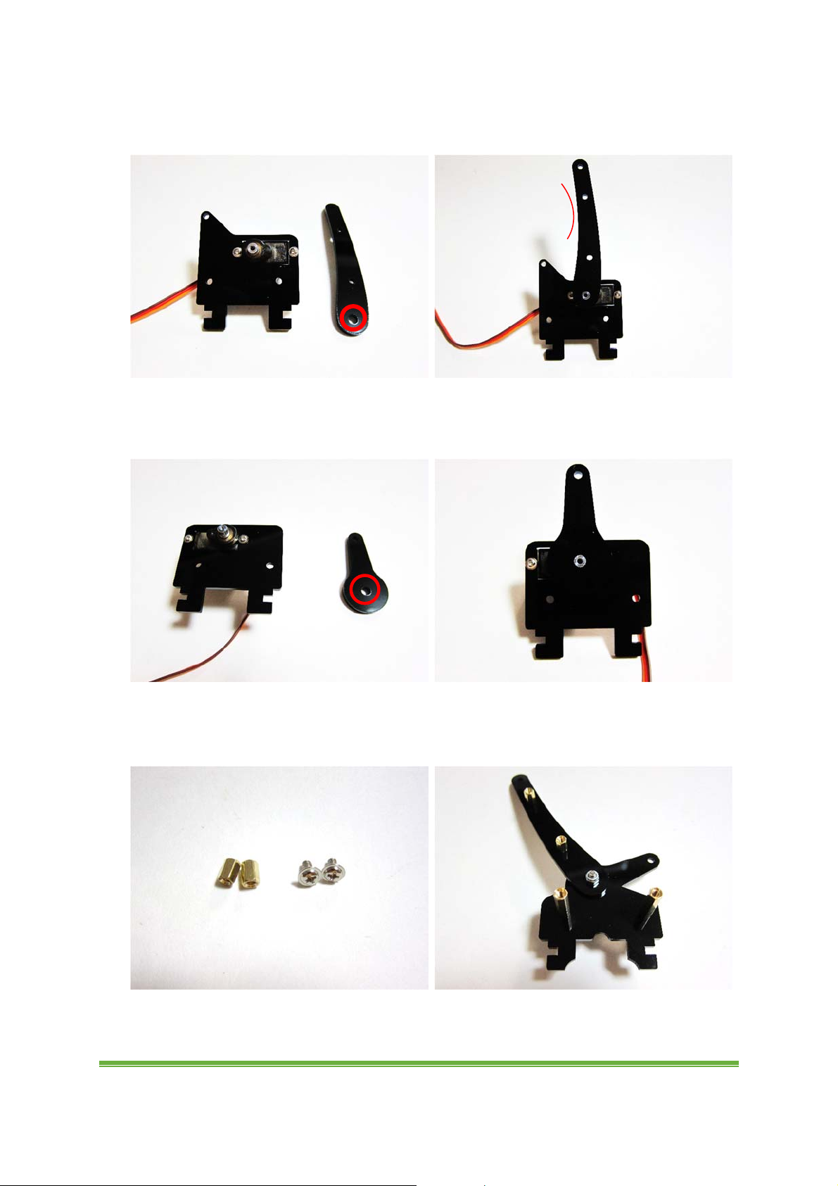
3. Fix the metal standoff with the screws as follow.
4. Take the round part as follow and fix a servo to it with 2 small truss head screws
and nuts.
5. Take 3 x M3 pan head 8mm screws and fix the part to the base.
www.eLabpeers.com Page 6
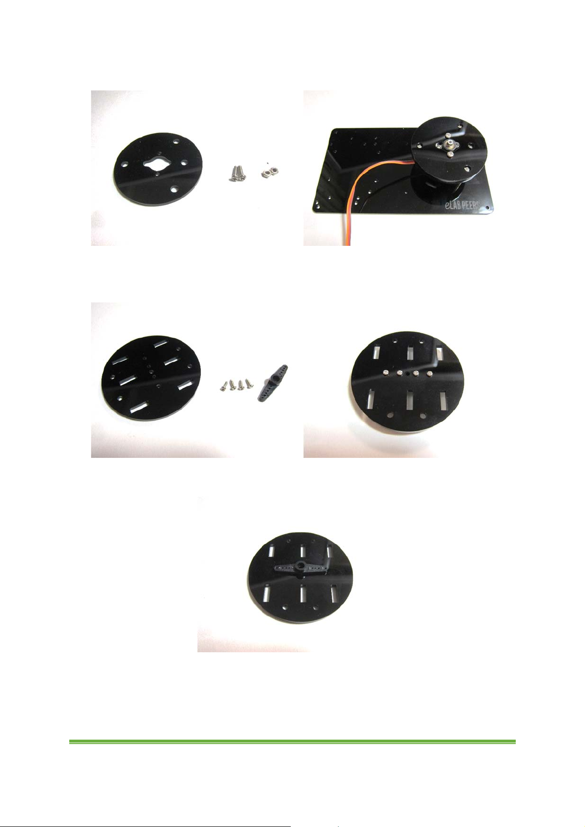
6. Fix another round part with 2 x M3 pan head 12mm screws and nuts as follow.
7. Take a round part, 4 small screws with sharp point and a plastic servo horn. Fix the
horn to the round part as follow.
8. Another view.
www.eLabpeers.com Page 7
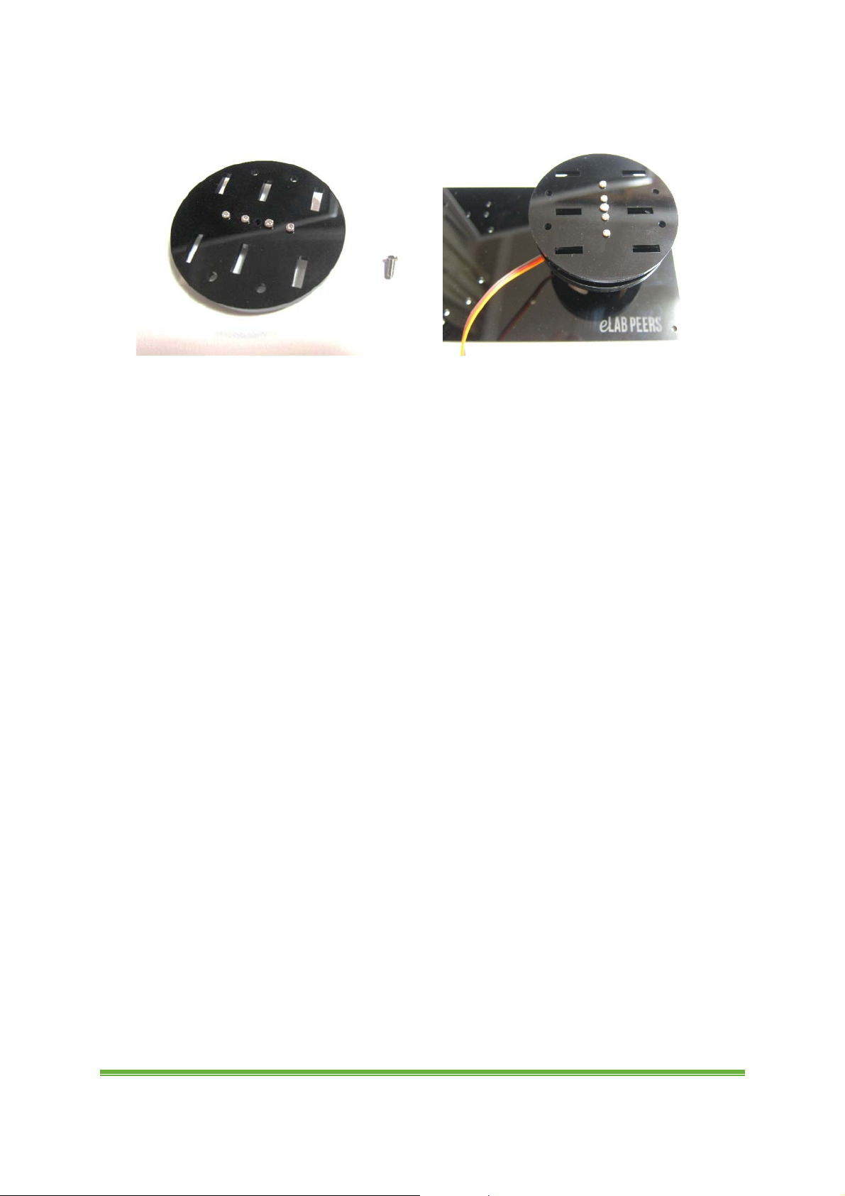
9. Fix this round part with a 7mm pan head screw to the servo on the base as follow.
www.eLabpeers.com Page 8

B. Body
B
1. Take the part as follow and fix a servo to it with 2 small truss head screws and
nuts.
A
2. Take the part as follow and fix a servo to it with 2 small truss head screws and
nuts.
3. Take the part as follow. Pick 2 metal standoff with screw point and pass them
through the holes as follow. (Note the position)
www.eLabpeers.com Page 9
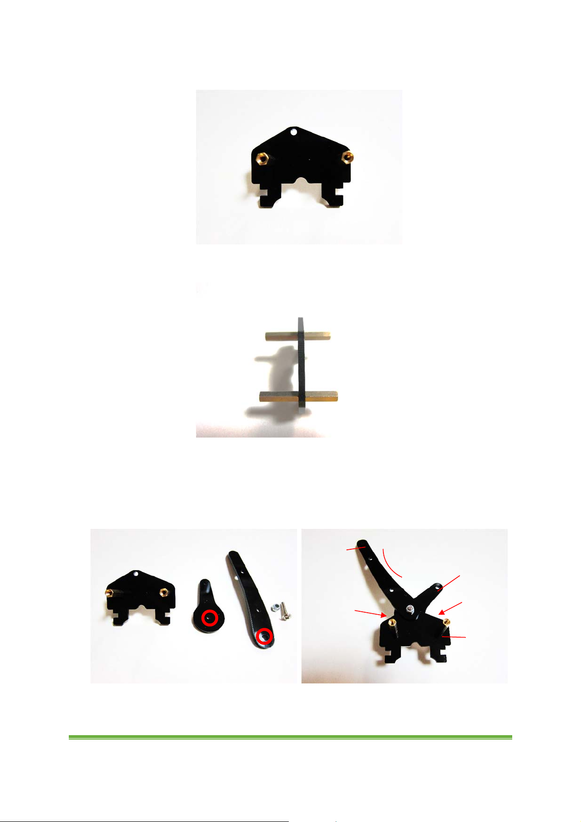
4. Fix 2 x 17mm metal standoff to the part.
C
5. Another view.
6. For C, take the parts, a M3 truss head 15mm screw and seal nut as follow. Please
note that the holes circled below should be in round shape. Fix these parts together
with the following order. Do not fix the nut too tight or too loose. Make sure the parts
can be moved freely. (Note the direction)
C
Top
Bottom
Long
Short
Middle
www.eLabpeers.com Page 10
7. For B, take the parts as follow. Please note that the hole circled below should be in
zigzag shape. Fix the part to the servo. (Note the direction)
B
8. For A, take the parts as follow. Please note that the hole circled below should be in
zigzag shape. Fix the part to the servo. (Note the direction)
A
9. For C, take 2 x M3 truss head 6mm screws and 6mm metal standoff. Fix them to C
as follow. (Note the position)
C
www.eLabpeers.com Page 11
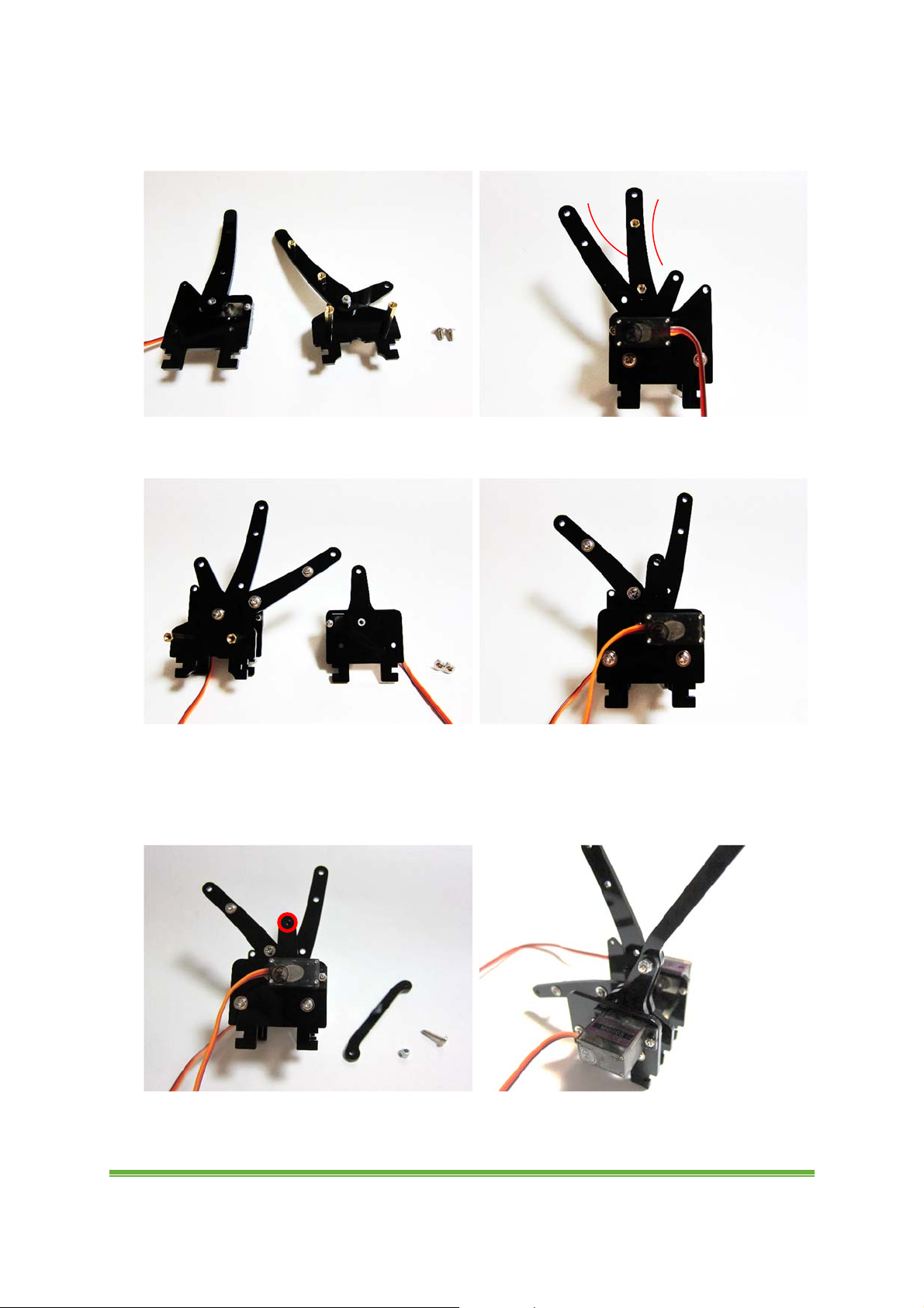
10. Take 2 x M3 truss head 6mm screws. Fix B and C together as follow. Curve of the
parts for upper arm should be in the same direction.
B
C
11. Take 2 x M3 truss head 6mm screws. Fix it with A together as follow.
A
12. Put another part between the circled holes shown and fix it with M3 truss head
15mm screw and seal nut as follow. Do not fix the nut too tight or too loose. Make sure
the parts can be moved freely. (Note the position)
www.eLabpeers.com Page 12
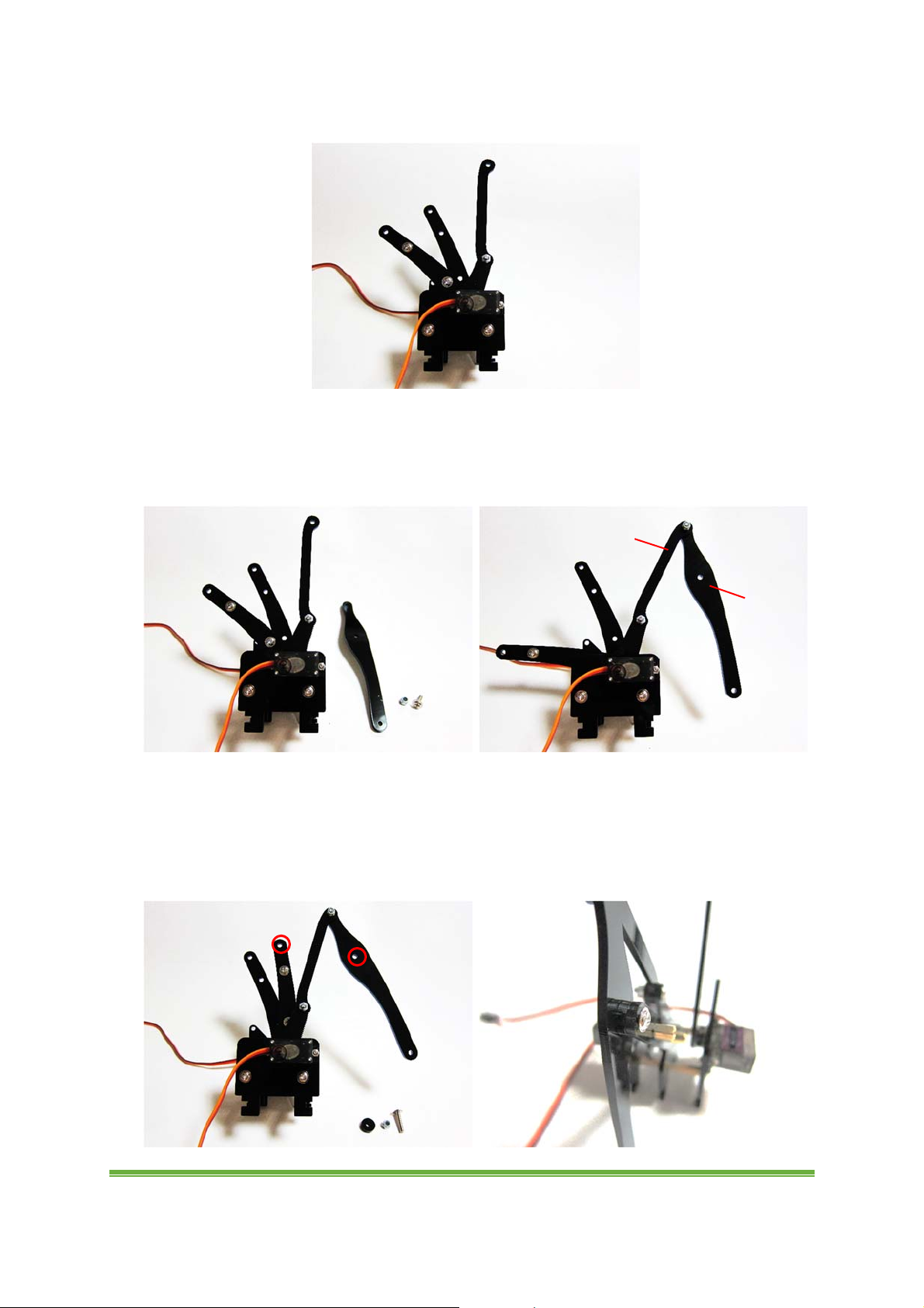
13. Another view.
14. Fix the part for lower arm with M3 truss head 10mm screw and seal nut as follow.
Do not fix the nut too tight or too loose. Make sure the part can be moved freely. (Note
the position)
Top
15. Move the parts so that two circled holes are align. Place an acrylic ring between
two holes. Fix them with M3 truss head 15mm screw and seal nut as follow. Do not fix
the nut too tight or too loose. Make sure the parts can be moved freely. (Note the
position)
Bottom
www.eLabpeers.com Page 13
16. Another view.
17. Flip it. Fix the part with M3 truss head 10mm screw and seal nut as follow. Do not
fix the nut too tight or too loose. Make sure the part can be moved freely. (Note the
position)
Bottom
Top
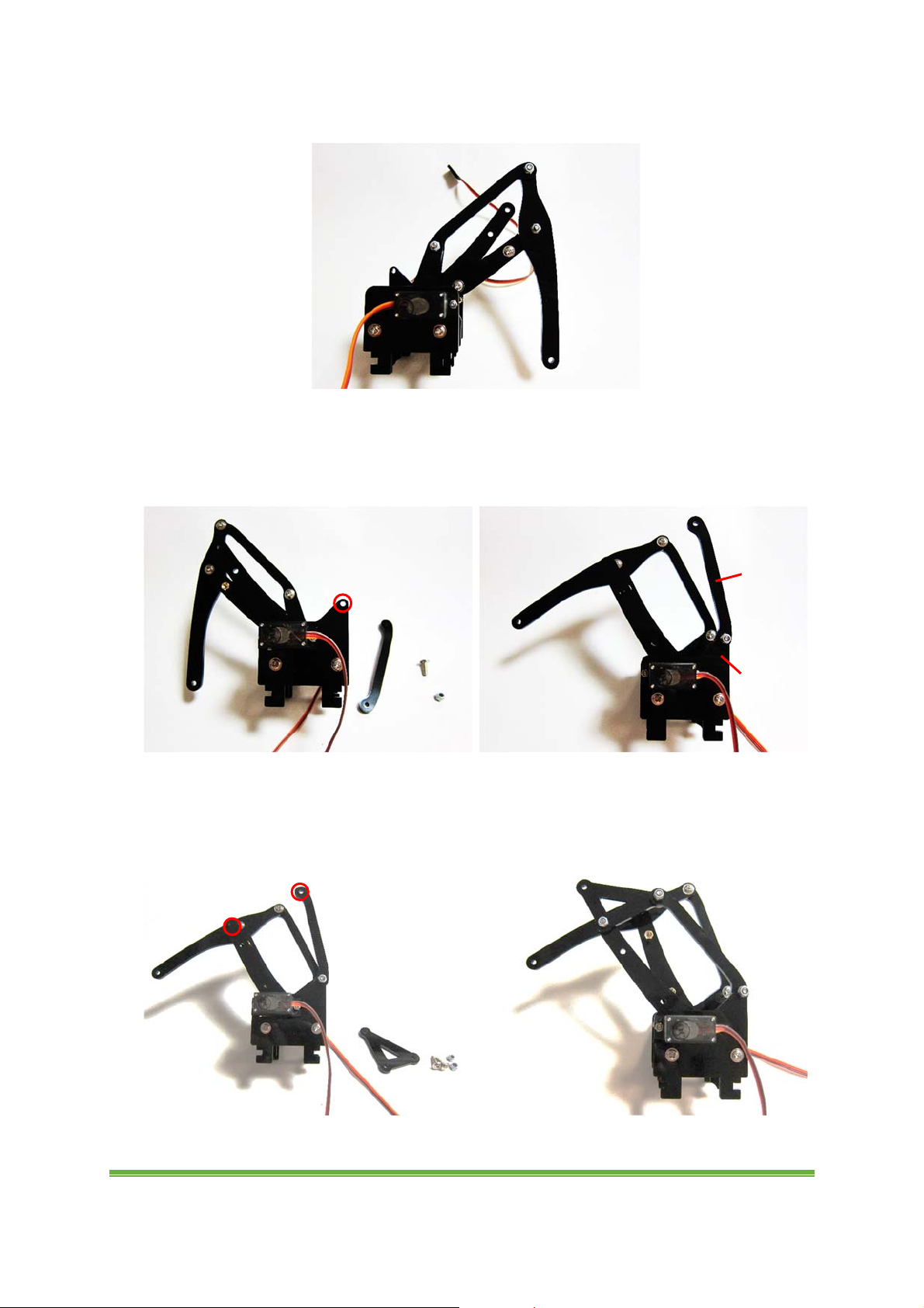
18. Fix triangle part with 2 x M3 truss head 10mm screws and seal nuts as follow. They
should be fixed in the correct order. Do not fix the nut too tight or too loose. Make sure
the parts can be moved freely. (Note the position)
www.eLabpeers.com Page 14
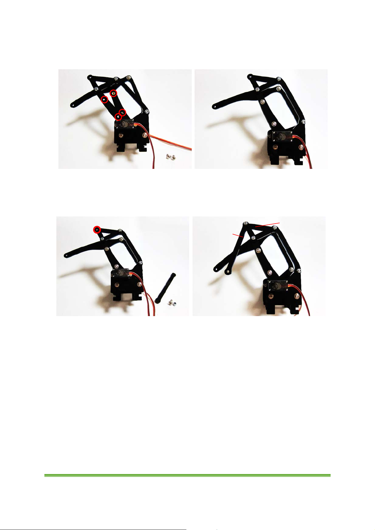
19. Move the parts so that the circled holes are align. Fix them with M3 truss head
6mm screw to metal standoff as follow. (Note the position).
20. Fix the part to the circled hole with M3 truss head 10mm screw and seal nut as
follow. They should be fixed in the correct order. Do not fix the nut too tight or too
loose. Make sure the parts can be moved freely. (Note the position)
Bottom
Top
www.eLabpeers.com Page 15
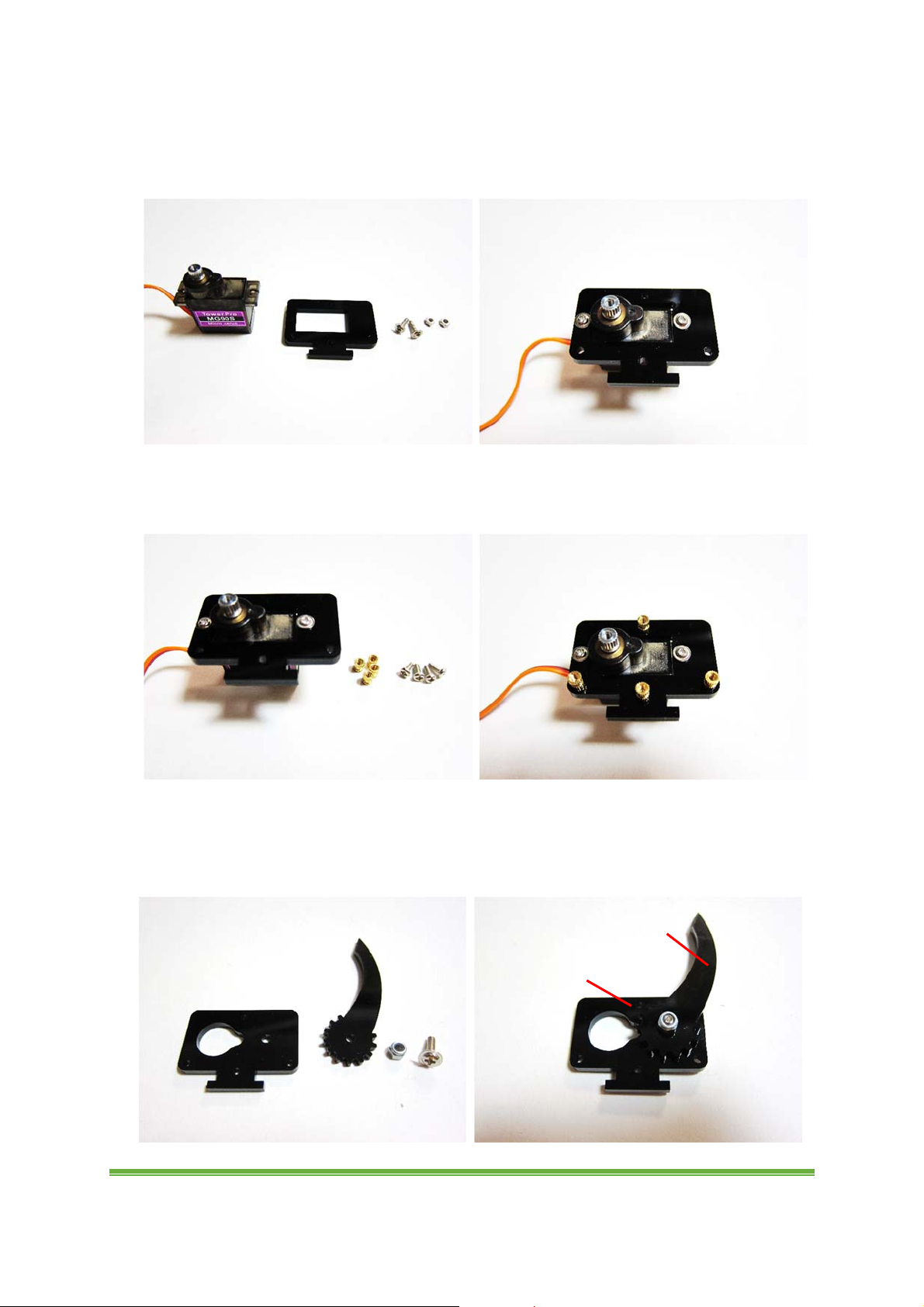
C. Claw
1. Take the part as follow. Fix a servo to it with 2 small truss head screws and nuts.
2. Take 4 small metal standoff and 4 small 5mm pan head screws. Fix the metals
standoff to the part as follow.
3. Fix the parts with M3 truss head 10mm screw and seal nut as follow. They should be
fixed in the correct order. Do not fix the nut too tight or too loose. Make sure the parts
can be moved freely. (Note the position)
Top
Bottom
www.eLabpeers.com Page 16
 Loading...