

E+L RK 4004 User Manual
Digital controller RK 4004 en
BEA--250482-EN-03
Description J
1. Function 2
2. Type overview 7
3. Assembly 7
4. Installation 8
4.1 Terminal assignments X 1 to X 21 9
4.2 Setup operation 10
5. Parameters 13
5.1 Parameter list 13
5.2 Explanation of parameters 20
5.3 "Three position controller" upgrade 57
6. Setting values 59
7. Technical data 61
Software: RK 4004-0003 F_ZG
U Page 2
Digital controller RK 4004
1. Function
1.1 Purpose
Explanation of symbols ➜ = jobs to be performed
= important information and instructions
Controller card RK 4004 is used to control a DC actuator with speed
and position feedback. For this purpose a current controller, speed
controller, position controller and motor output stage are integrated
on the card. Appropriate sensors may be attached via a CAN bus for
the position controlling of running webs and following-up of tools.
Operation is via a command device with text display and/or a digital
input-output card.
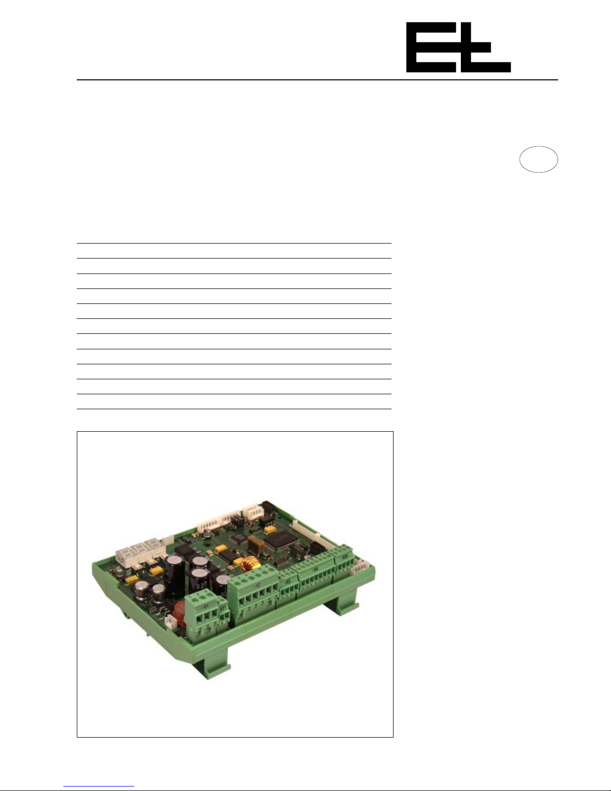
The controller card consists of the following modules:
- a processor with data memory
- several JST plug sockets
- several terminals
- a green LED for "output stage on stand-by"
- a red LED for the "overcurrent" display
- three segment displays
- and three keys (setup, increase value, decrease value)
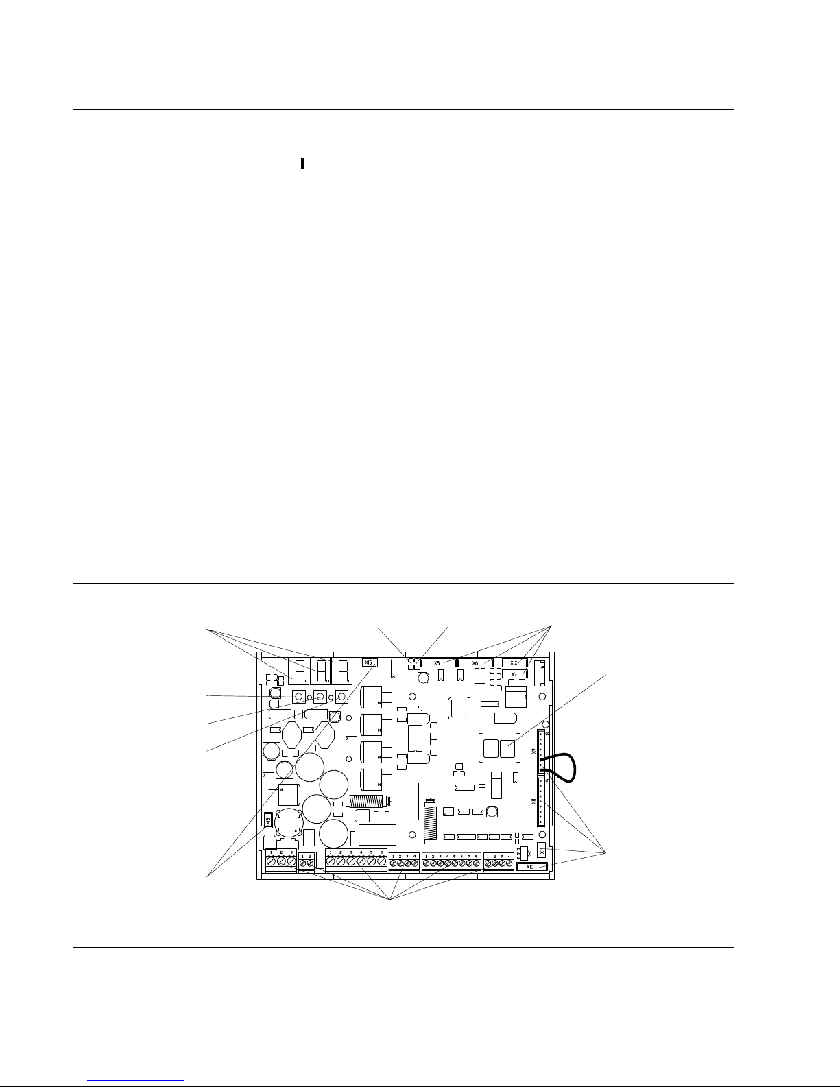
JST plug sockets
Terminals
1.2 Design
Green LED Red LED
Data memory
JST plug sockets
Segment displays
Keys:
"Setup"
"Decrease value"
"Increase value"
JST plug sockets

U Page 3
Digital controller RK 4004
The operating principle depends on the mode selected. The following
operating modes are possible:
Actuator manual:
In manual mode the actuator may moved to the left or right to a required position. The speed may be set in the appropriate parameter.
Actuator center position:
The actuator is positioned at the set center whereby first of all it is
moved to the reference switch and the internal position controller is
adjusted. The actuator is then moved to the set center position. The
reference switch should be mounted so that when the actuator is in
its center position the switching point of the reference is crossed thus
assuring that the actuator may be center-positioned without any major positioning movement.
Automatic mode:
In automatic mode the web or tool is guided to the set position. Prerequisite to guiding is that guider lock is released.
Guider lock in automatic mode:
Guider inhibiting is only effective in automatic mode and may be activated on controller card RK 4... or via an interface.
Web offset:
A web offset may be set in automatic mode. A web offset means that
the set position value may be changed positively or negatively.
In the case of fixed sensors or a single motor support beam with two
positioning carriages, web offsetting is limited to 75 % of the sensor
measuring range. On the remaining applications with support beams
the web offset may be extended to include the entire support beam
position range.
Oscillation:
In automatic mode a oscillating set value is additionally added to the
set position value. The oscillating mode, period and path may be set
in the appropriate parameters or via a command station. In the case
of fixed sensors oscillation is only possbile within 75 % of the
measuring range.
Park sensor:
When using a support beam the positioning carriage along with the
sensor/tool located on it are moved (outwards) to the outer end position.
Search for edge:
The sensor searches for and follows the web edge until the operating
mode is changed by, e.g. a guider enable.
1.3 Operating principle
U Page 4
Digital controller RK 4004
In a control structure for proportional actuators the web or tool actual
position value is compared with the required set position value and, in
the event of a deviation, it is transmitted to a P position controller as a
control difference. The resultant set speed value is compared with the
actual speed value and transmitted to the PI speed controller. The latter emits a pulse width-modulated signal at the output stage.
The following are available as proportional actuators:
DRS pivoting frame, VWS turning rod, SRS steering roller, WSS winding station, SVS push roller SVS and VSS positioning and follow-up
controller.
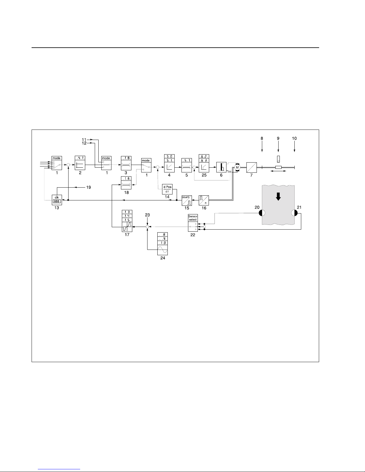
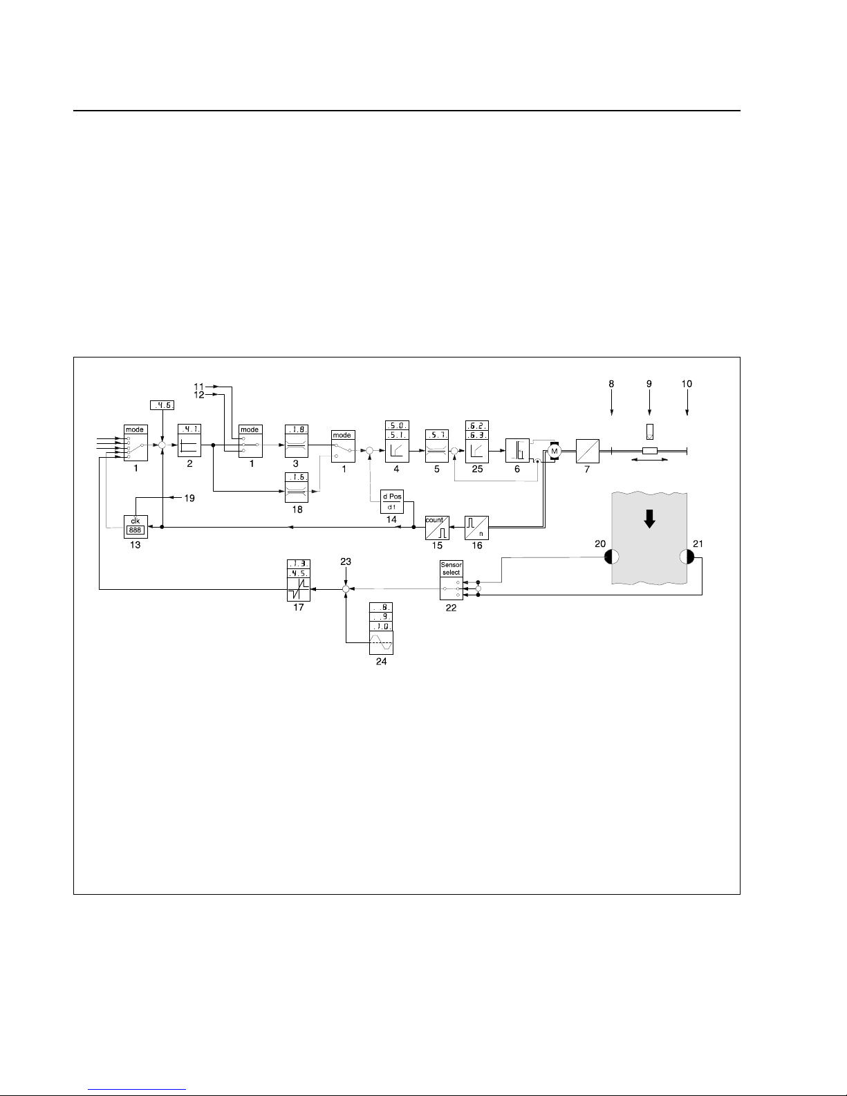
1.4 Control structure with
constant controlling for
proportional actuators
Control structure legend
1 Operating mode
2 Actuator position controller
3 Max. variable actuating speed in manual
4 Speed controller
5 Variable current controller
6 Power output stage
7 Gearing with spindle
8 Right end position
9 Center position
10 Left end position
11 Right offset
12 Left offset
13 Actual position memory
14 Actual speed value recording
15 Counter
16 Incremental encoder
17 Web position controller
18 Max. variable actuating speed in automatic
19 Memory command at stop
20 Right edge sensor
21 Left edge sensor
22 Sensor selection (right web edge, left web edge, web center)
23 Web offset
24 Oscillation generator
25 Current controller
U Page 5
Digital controller RK 4004
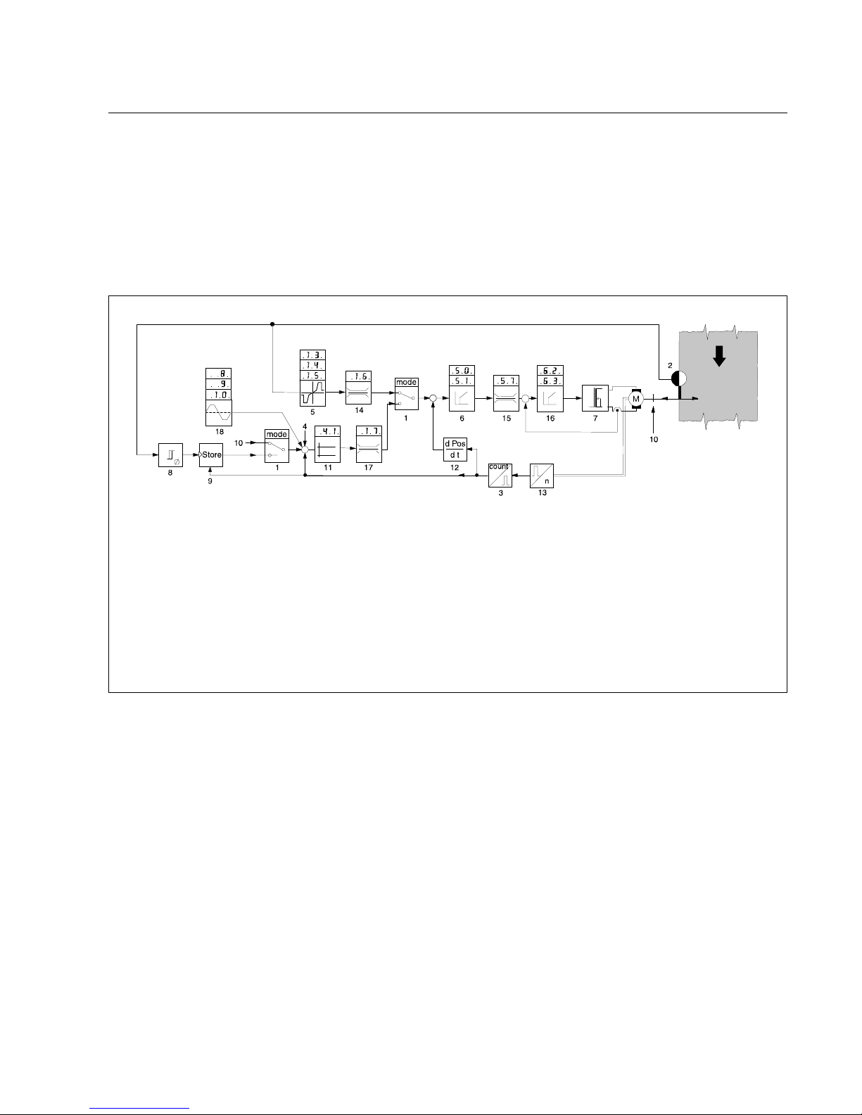
1.5 Control structure with
constant controlling for
support beams
Control structure legend
1 Operating mode
2 Sensor
3 Counter
4 Web offset
5 Edge sensor position controller
6 Support beam speed controller
7 Power output stage
8 Sensor zero point detector
9 Memory for edge position
10 Park position
11 Support beam position controller
12 Actual speed value recording
13 Incremental encoder
14 Max. variable actuating speed in search for edge mode
15 Variable current controller
16 Current controller
17 Variable actuating speed during positioning
18 Oscillation generator
In a control structure for a support beam a set speed value is determined on the basis of the sensor signal via the P position controller
that is transmitted to the speed controller. The resulting set speed value is compared to the actual speed value and transmitted to the PI
speed controller. The latter emits a pulse width-modulated signal at
the output stage. In "search for edge" or "hybrid" modes the sensor is
driven to follow-up the web edge.
Available as proportional actuator:
Support beam VSS
U Page 6
Digital controller RK 4004
Control structure legend
1 Operating mode
2 Actuator position controller
3 Max. variable actuating speed in manual
4 Speed controller
5 Variable current controller
6 Power output stage
7 Gearing with spindle
8 Right end position
9 Center position
10 Left end position
11 Right offset
12 Left offset
13 Actual position memory
14 Actual speed value recording
15 Counter
16 Incremental encoder
17 Web position controller
18 Max. variable actuator speed in automatic
19 Memory command at stop
20 Right edge sensor
21 Left edge sensor
22 Sensor selection (right web edge, left web edge, web center)
23 Web offset
24 Oscillation generator
25 Current controller
1.6 Control structure with constant controlling for integral actuators
In the case of a control structure for integral actuators the web actual
position value is compared to the required web set position value
and, in the event of a deviation, it is transmitted as a control difference to a P position controller. The latter provides the necessary set
position value for the actuator. The current actual actuator position
value is compared to the required set position value and transmitted
as a control difference to the actuator position controller. The latter
generates the set speed value which is compared to the actual speed
value, the difference being fed to the PI speed controller which emits
a pulse width-modulated signal at the output stage.
Available integral actuators:
SWS segmented roller guider, VGA pivoting roller, BCS edge and
width spreader
U Page 7
Digital controller RK 4004
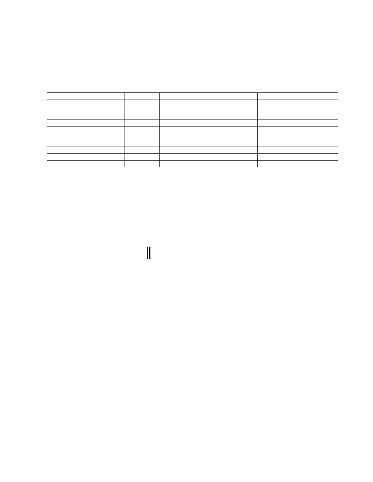
Type RK 4004 AK 4002 LK 4203 RT 4019 DO 2000 AK 4014
DC 0310 X X
DC 0311 X X X
DC 0340 X
DC 0341 X X
DC 0360 X X
DC 0361 X X X
DC 1310 X X X
DC 1340 X X
DC 2340 X X
DC 2341 X X X
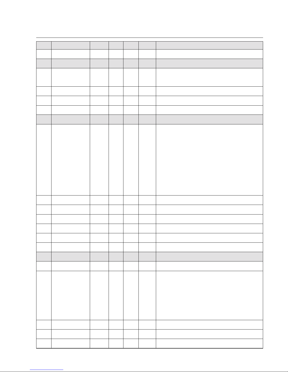
2. Type overview
The following table provides an overview of the most common digital
controllers. The individual digital controllers (DC) are listed in the vertical column. The crosses mark the components belonging to them
(AK ...., LK ...., etc.).
3. Assembly
Controller card RK 40.. is usually mounted in a sheet steel housing or
E+L device.
If the controller card is supplied on its own it should be mounted in a
control cabinet away from heavy current-carrying modules.
The maximum distance to the DC actuator must not exceed
10 m.
U Page 8
Digital controller RK 4004
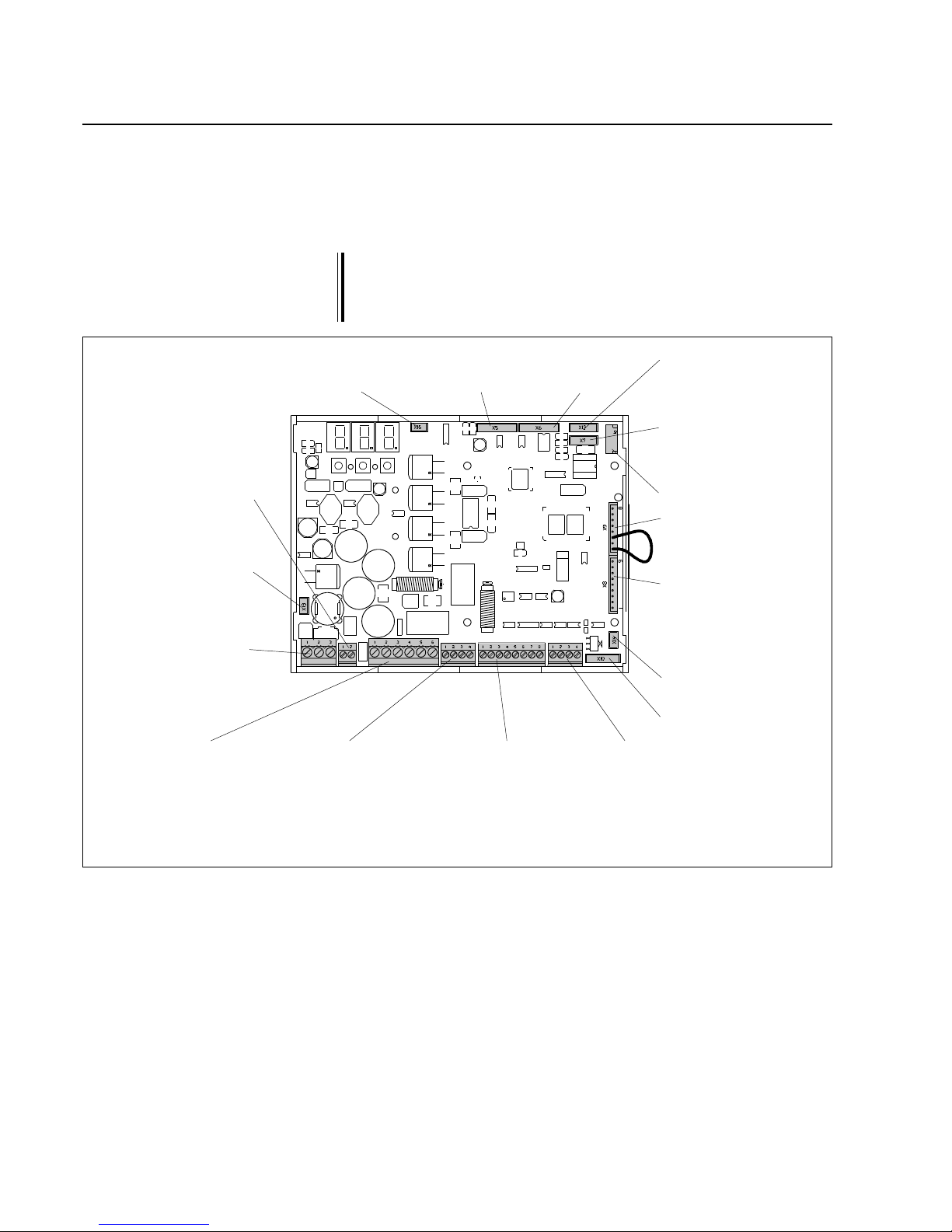
RK 40.. terminal assignments
X 9 serial bus
X 8 Analogue card
AK 4002
(only when analogue sensors are
used)
X 14 External configu-
ration adapter
X 10 Optical incre-
mental encoder
X 7 CAN connection
with LED display
for CAN device
connector
X 6 Left
digital
sensor
X 5 Right
digital
sensor
X 12 CAN connection
without LED display
for internal device
networking
X 15 Fan
X 13 Supply voltage
for further E+L
modules
X 2 DC actuator
and incremental encoder
X 3 Command sta-
tion for web
offset RE .... or
signal for pathdependent
oscillation
X 4 Reference
switch, guider
lock and end
position signal
X 20 End switch
X 21 Supply voltage
for further E+L
modules
X 1 Operating volta-
ge
The wiring diagram indicates which connectors are assigned.
The guider lock is intended for on-site requirements where the actuator is to be stopped in its current position. If the guider lock is closed
(make contact) the actuator remains in this position until the contact
is open again.
X 11 SPI bus
4. Installation
➜ Connect electrical leads according to the attached wiring diagram.
➜ Shield and run signal lines away from heavy current-carrying
leads.
The DC actuator motor line must be run separately (separate cable) from the incremental encoder line.
The connection line between the controller card and DC actuator
may be run in one lead up to a length of 3 m. From a distance of
3 m to 10 m the motor and incremental encoder lines must be
run separately.

U Page 9
Digital controller RK 4004
Terminal No. Input Output Assignment
X 1 1 X +24 V DC supply voltage
2X 0 V
3 X Ground
X 2 1 X DC actuator
2 X DC actuator
3 X Incremental encoder on DC actuator track A
4 X Incremental encoder on DC actuator track B
5 X +24 V DC
6X0 V
X 3 1 X +24 V DC
2 X Web offset or path-dependent or
Oscillation signal or
automatic mode signal (for minimum operation only)
3X0 V
4 X Sensor range limit
X 4 1 X Guider lock
2 X 0 V potential 0 V for controller lock
3 X +24 V DC reference switch
4 X Reference switch signal
5 X 0 V reference switch
6 X +24 V DC
7 X Actuator end position signal
8X0 V
X 7 1 X X CAN High
2 X X CAN Low
3 X LED +
4 X LED -
X 10 1 X GND (0 V)
2 X (Index) 3X Track A
4 X +5 V
5X Track B
X 12 1 X X CAN High
2 X X CAN Low
3 - - free
4 - - free
X 13 1 X +24 V
2 X GND 0 V
X 15 1 X +12 V
2 X Switch output
X 20 1 X +24 V
2 X Actuator 2nd end position signal
3X0 V
4 X system on stand-by
X 21 1 X +24 V
2X0 V
4.1 Terminal assignments X 1 to X 21
U Page 10
Digital controller RK 4004
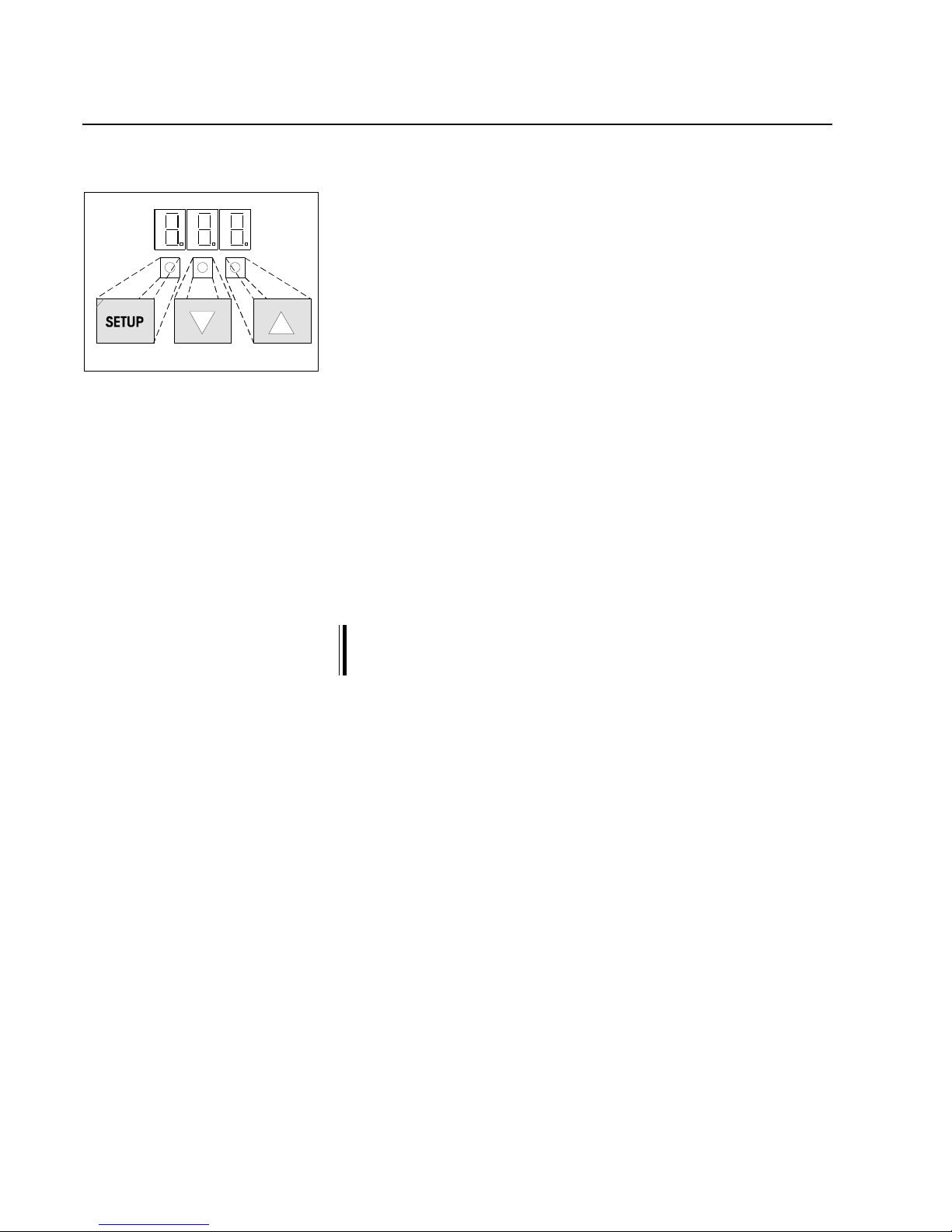
The three keys and the displays are used as the setup control panel.
The key assignment (setup, decrease/increase value) is indicated in
the illustration opposite. The following applications are possible:
4.2.1 Setting the controller card device address
4.2.2 Current error display
4.2.3 Setting parameters
Prior to commissioning the device address of controller card
RK 4004 must be checked and changed as necessary.
➜ Press both keys "decrease value" and "increase value" at the
same time. The group number is indicated via the "decrease value
" key and the device number via the "increase value" key. If both
keys are held down for longer than approx. 4 seconds the device
address will start to flash.
➜ If the device address deviates from the required address it may be
changed via the keys.
If none of the keys are actuated the device address will be saved
after approx. 20 seconds have elapsed and a software reset is
triggered.
4.2 Setup operation
4.2.1 Set controller card
device address
U Page 11
Digital controller RK 4004
In normal circumstances the display on the controller card indicates
only three dots. These three dots signal that no errors are present .
A flashing number signals an error. The number indicates the error
code. If several errors are present at the same time, the error with the
highest priority will be indicated. If this error is no longer present, the
display will indicate the next error.
Below is a list of possible errors:
4.2.2 Current error display
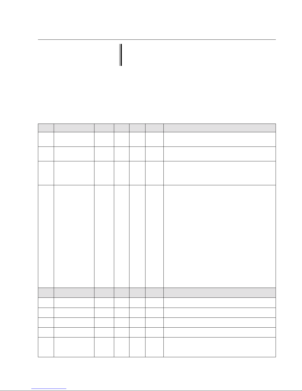
No. Error display in Description Output at
CANMON terminal X 20.4
1 UDC-power low 19.5 VDC operating voltage not attained 0
2 UDC-power high 30.5 VDC operating voltage exceeded 0
3 I motor high set maximum cut-off current exceeded 4 temp case high heat sink over 70 oC0
5 encoder fault incremental encoder motor fault 6 encoder invers incremental encoder motor inverted 7 sensor R fault no message from right sensor 8 sensor L fault no message from left sensor -
9 gearconstant fault calculated gear constant produces impermissible value 10 motor line fault motor line interrupted 0
12 power stage defect motor power stage defective 0
13 motor blocked motor blocked due to overloading (I = max. & n = 0)
Attention! output is set after 5 seconds only 0
14 ref. switch error several reference switch errors detected. 15 end switch error end position proximity switches incorrectly configured 16 24Vext. fault ext. supply voltage overloaded. 0
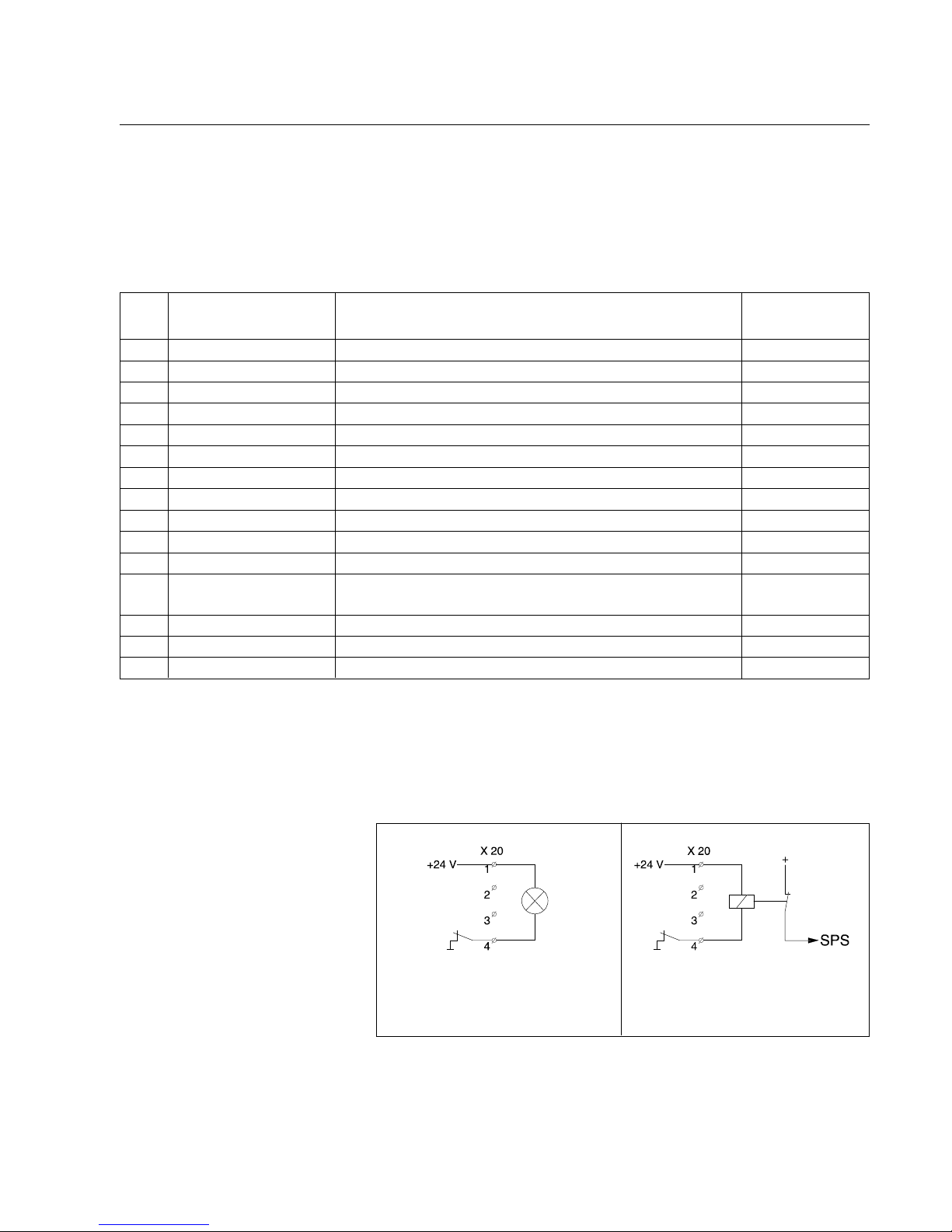
4.2.3 Output X 20.4 In the case of certain errors (see table) output X 20.4 is switched to
"0". The internal switch on the controller card that furnishes a connection to ground is opened.
The following circuit variants are recommended:
Lamp "ON" = system on stand-by
Lamp "OFF" = error
PLC "1" = system on stand-by
PLC "0" = error
U Page 12
Digital controller RK 4004
4.2.3 Parameter setting
Para-
meter-
value
Para-
meter
Start setup mode
Enter device number
Enter group number
yes
Expanded setup mode
no
ja
no
Quit setup mode
+
May parame-
ter value be
changed
Select
further
parameters
+
+
or
+
or
+
or
or
+
or
+
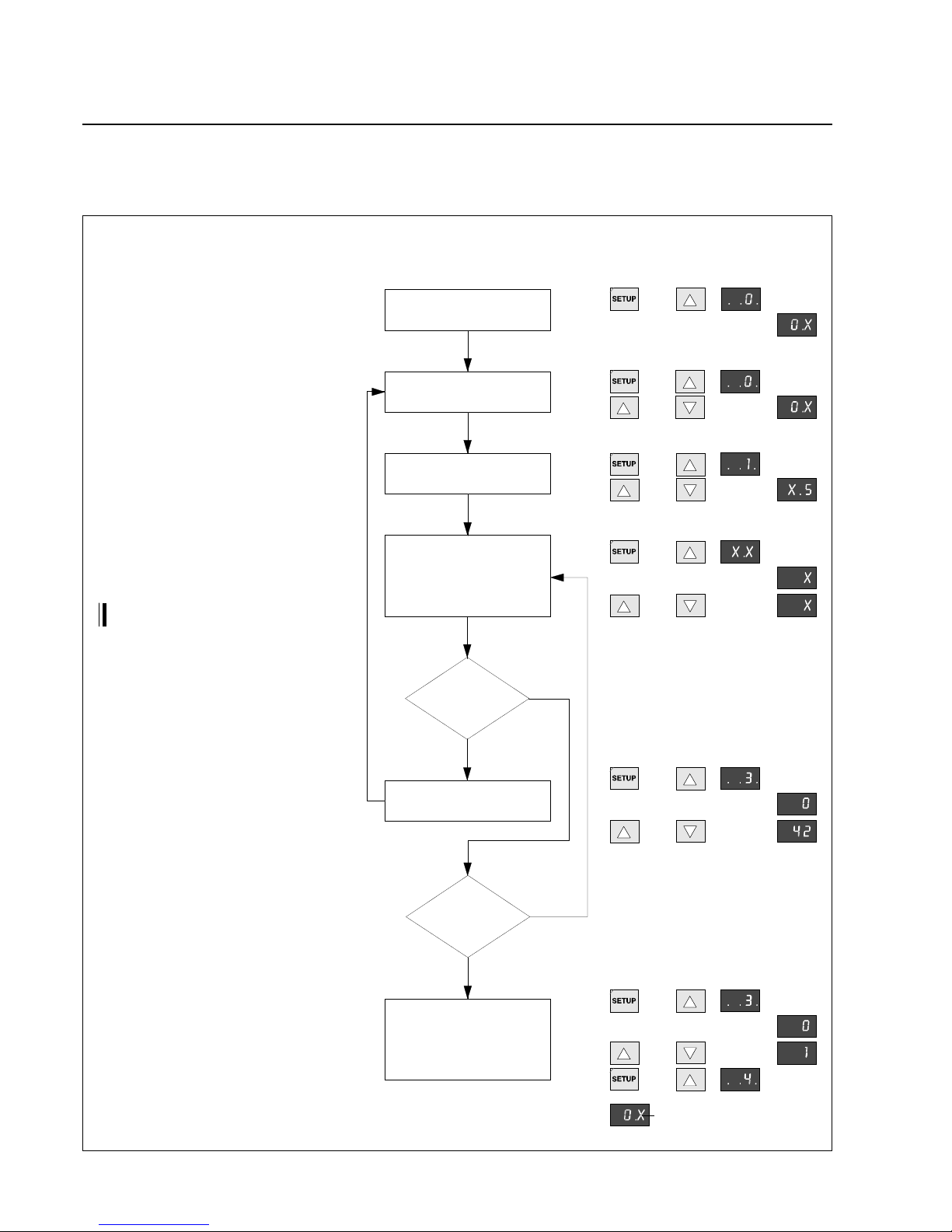
Start setup mode: press the setup and additionally the increase value key (press the setup key
first). The green LED on the setup key will flash .
Enter device number: press and hold down the
setup key and select parameter 0 via the increase
value key. Release the setup key again and enter
the device number via the increase or decrease
value keys (device number is specificed in the
block diagram)
Enter group number: press and hold down the
setup key and select parameter 1 via the increase
value key. Release the setup key again and enter
the group number via the increase or decrease
value keys (group number is specified in the
block diagram)
Select and change parameters: press and hold
down the setup key and select the required parameter via the increase value key. Release the setup key again and enter the required parameter
value via the increase or decrease keys.
Incorrect parameter changes may impair
the function of the entire system !
Select expanded setup mode: select device
number X.5, then press and hold down the setup
key and select parameter 3 by pressing the
increase value key. Release the setup key again
and enter parameter value 42 via the increase or
decrease value keys.
Quit setup mode: select device number X.5, then
press and hold down the setup key and select
parameter 3 by pressing the increase value key.
Release the setup key again and enter parameter
1 by pressing the increase or decrease value key.
Press and hold down the setup key
and press the increase value key once. Release
the setup key again.
X is used as a place retainer
Select parameter
Change parameter value
Basic operation in setup mode:
All parameters in the CAN network may be selected and changed by
the three keys. The following flow diagram illustrates basic operation
with the setup editor:
U Page 13
Digital controller RK 4004
In setup mode parameters may be displayed and to some extent
changed as well. In order to access the controller card setup
mode a command station DO .... , a operating panel RT .... or an
E+L CANMON program is required.
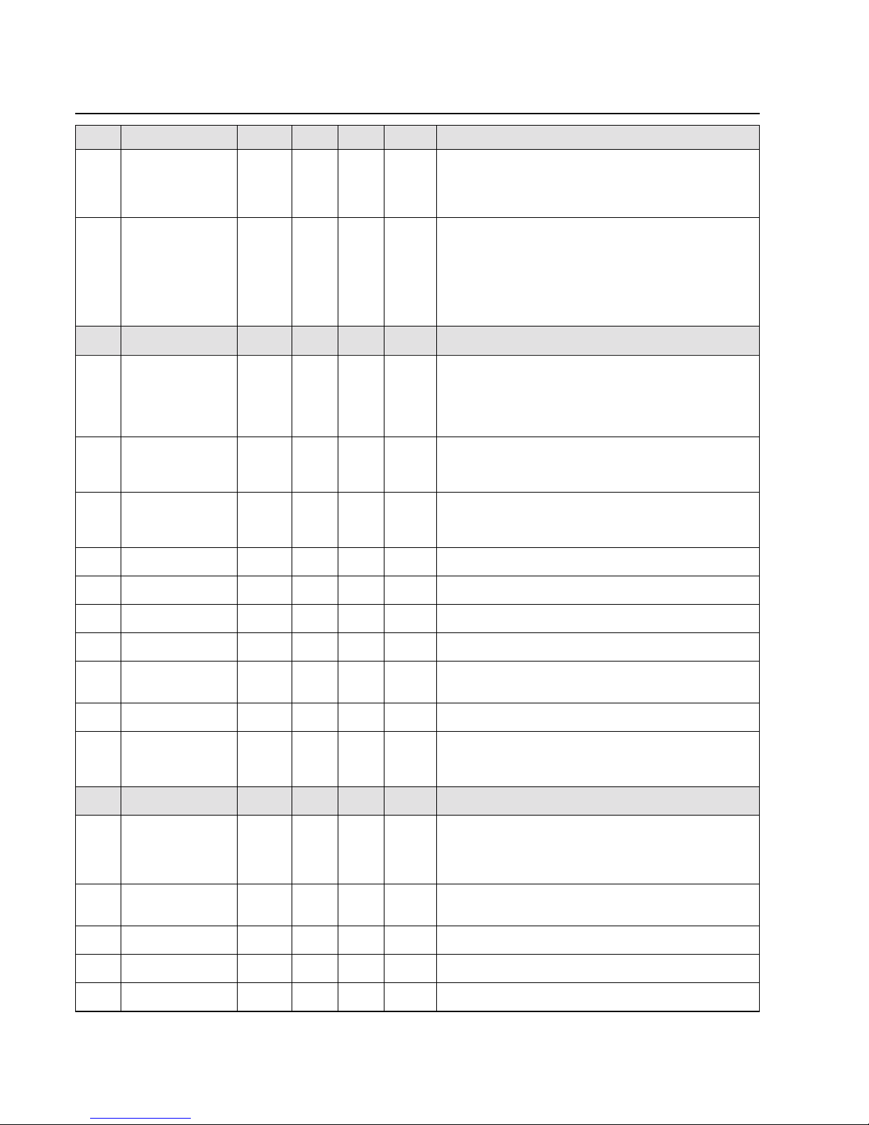
The parameter numbers are listed in the Number field of the table, in
the Name field the abbreviation. The Default field indicates the standard settings, Min and Max are the permissible limit values respectively. The unit is indicated in the Unit field. The Description explains
the parameter function. If a dot (•) comes after the parameter number
this indicates that it is a display parameter, the value of which cannot
be changed.
5. Parameters
5.1 Parameter list
No. Name Default Min. Max. Unit Description
..0. edit device 5 1 F hex select device number
see block diagram for device number
..1. edit group 0 0 7 hex select group number
see block diagram for group number
..2. reset settings 0 0 2 Works settings
0 = no function
1 = perform customer settings
2 = perform internal default setting
..3. start service 0 0 199 Starting a function
0 = no function
1 = reset controller
2 = save parameter
10 = actuator initialisation run (device X.5)
11 = support beam initialisation run
(device x.6, x.7, x.8, x.9, x.10, x.11)
12 = actuator initialisation run, with specification
of the gear constants (device x.5)
13 = actuator guiding criterion photo
(for integral controller only)
22 = saving of application parameters
30 = preset for general web guider parameters
31 = preset for sensor support beam VS 35 parameters
32 = preset for 3-position controller parameters
33 = preset for DR 11.. / DR 12.. parameters
34 = preset for support beam VS 50.. parameters
42 = select expanded setup
44 = save customer settings
98 = delete error memory
99 = delete data memory
..4. • RK 4004 1.6 1.2 1.6 E+L Software version
..5. • webedge offset Parameter title
..6. weboffset 0.00 -325.00 325.00 mm Web offset
..7. step width 0.10 0.01 10.00 mm Step width for web offset
..8. osc. amplitude 0.0 0.0 500.0 mm Oscillation amplitude +/-
..9. osc. cycl. time 20 1 700 sec. Oscillation cycle time
cycle-dependent = sec/ cycle
path-dependent = pulse/ cycle
U Page 14
Digital controller RK 4004
No. Name Default Min. Max. Unit Description
.1.0. osc. wave form 95 5 95 % Oscillation progression
5% = square wave
50% = trapezoidal wave
95% = delta wave
.1.1. >osc. trigger mode 2 0 7 Oscillation operation
0 (4) = operation via keyboard
1 (5) = operation via AUTO key
2 (6) = oscilation OFF
3 (7) = oscillation ON
Values in () for path-dependent oscillation
.1.2. • webedge controller Parameter title
.1.3. prop range +/- 10.0 -2000.0 2000.0 mm Guider proportional range
Web offset in mm at which the DC actuator
runs at maximum speed.
Decrease value in case of inaccurate guiding!
Increase value in case of uneven guiding!
.1.4. dual-rate width 30 10 90 % Window width in % in relation to the sensor scan range
This value is used to establish the switch point for
determing the dual rate characteristic curve.
.1.5. dual-rate level 100 0 150 % Positioning velocity reduction
This value is used to determine % motion speed at
the switch-over point.
.1.6. velocity auto 20 0 1000 mm/s Max. positioning velocity speed in automatic mode
.1.7. velocity pos 50 0 1000 mm/s Positioning velocity speed in positioning mode
.1.8. velocity jog 10 1 1000 mm/s Positioning velocity speed in jog mode
.1.9. velocity defect 1 1 1000 mm/s Positioning velocity when exceeding the set threshold
.2.0. • derated velocity 1000 mm/s Display of velocity limited by internal functions
(only active for selecting in parameter 1.1.8.)
.2.1. reserved 21 not assigned at present
.2.2. defect range ± 10.0 0.0 2000.0 mm range for detecting a web fault
if not attained switching to the set "velocity defect" speed
will be performed
.2.3. • servo configuration Parameter title
.2.4. motion direction 0 0 1 Motion effective direction
0 = normal
1 = inverted
Depends on mounting position and web direction of travel
.2.5. motion range total 0.0 0.0 3270.0 mm Total motor position range on calibration
AG positioning path must be entered prior to calibration
.2.6. positionrange + 0.0 0.0 3270.0 mm Positive motor position range
.2.7. positionrange - 0.0 -3270.0 0 mm Negative motor position range
.2.8. alarm limit % 75 0 100 % Limit value for end position early warning
U Page 15
Digital controller RK 4004
No. Name Default Min. Max. Unit Description
.2.9. reserved 29 not assigned at present
.3.0. reference offset 0.0 -3270.0 3270.0 mm Reference switch offset
Distance between reference switching point and
AG- positioning range center
.3.1. center offset 0.0 -3270.0 3270.0 mm Centring offset
Distance between actuator positioning range center and
required actuator 0-position in „center position“ mode.
.3.2. system offset 0.0 -3270.0 3270.0 mm System offset
Distance between set actuator 0-position and the
reference point (e.g. machine center).
.3.3. • total resolution 0.0 0.0 3270.0 p/mm Motor gear constant
display only.
.3.4. encoder resolution 8 8 9999 p/revrev encoder resolution
entry of rev encoder resolution pulse/rev
(without 4-fold evaluation)
.3.5. rotation gear 8.0 0.1 100.0 Gear transmission on motor
Entry of gear transmission
.3.6. linear gear 4.0 0.1 250.0 mm/rev Linear gear transmission
Entry of transmission ratio from
rotational to linear movement
.3.7. mech. gearfactor 1.00 0.10 5.00 - Mechanical ratio
.3.8. reserved 38 not assigned at present
.3.9. reserved 39 not assigned at present
.4.0. • pos. controller Parameter title
.4.1. pos prop +/- 5.0 0.1 200.0 mm Position controller proportional range
.4.2. • act position 0.0 -3270.0 3270.0 mm Actual position (display only)
.4.3. • set position 0.0 -3270.0 3270.0 mm Set position (display only)
.4.4. pos source adress 00 00 7F - Master address
Address from which the master set position is received
.4.5. prop stroke +/- 100 0 2000.0 mm Actuator correction path in the event of
a web fault of (.1.3. prop range +/-)
.4.6. • photo auto offset 0 -2000.0 2000.0 mm Actuator offset between set center and set operating
point during automatic mode
is set for <SETUP>+<AUTO>.
Only if function is activated via „Configuration SYS“.
.4.7. • speed controller Parameter title
.4.8. max. motor speed 1250 100 4000 rpm Motor speed characteristic value
Value is required for speed limiting
.4.9. • act. speed rpm Current motor speed (display only)
.5.0. speed_P 2.00 0.01 10.00 P component for speed controller
.5.1. speed_I 0.10 0.01 5.00 I component for speed controller
U Page 16
Digital controller RK 4004
No. Name Default Min. Max. Unit Description
.5.2. accel. time 0.0 0.1 10.0 sec. Acceleration time
.5.3. • I-PWM Current I-PWM-value (display only)
.5.4. reserved 54 not assigned at present
.5.5. • current controller Parameter title
.5.6. cut-off current 8.0 0.0 10.0 A Cut-off current of motor output stage
.5.7. motorcurrent 1.0 0.0 7.0 A Max. permissible nominal motor current
.5.8. dyn. currentfactor 150 100 200 % Dynamic motor current rise
Motor is overloaded briefly by the variable factor
.5.9. therm. timeconst. 60 1 200 sec. Thermal time constant for brief motor current excess
.6.0. • limited current - -7.00 7.00 A Current permissible motor current
.6.1. • act. current - -20.00 20.00 A Actual measured motor current
.6.2. current_P 2.6 0.0 100.0 P component for current controller
.6.3. current_I 0.4 0.0 50.0 I component for current controller
.6.4. • set current Set motor current display
.6.5. reserved 65 not assigned at present
.6.6. reserved 66 not assigned at present
.6.7. reserved 67 not assigned at present
.6.8. • diagnostics Parameter title
.6.9. • system error xx Error display
1 = supply voltage < 20 V DC
2 = supply voltage > 30 V DC
3 = cut-off current exceeded
4 = heat sink temperature > 70 °C
5 = incremental encoder defective
6 = incremental encoder inverted
7 = no message from right sensor
8 = no message from left sensor
10 = motor line interrupted
11 = motor blocked
12 = motor output stage defective
13 = motor blocked
14 = reference switch has several switching points
15 = end pos. proximity switches incorrectly configured
16 = external voltage output overloaded
.7.0. reserved 70 not assigned at present
.7.1. reserved 71 not assigned at present
.7.2. • running time meter x h Running time meter
.7.3. • supplyvoltage 24DC xx.x V Operating voltage
.7.4. • temperature case xx
o
C Heat sink temperature
U Page 17
Digital controller RK 4004
No. Name Default Min. Max. Unit Description
.7.5. • temp. case max. xx
o
C Maximal heat sink temperature reached
.7.6. reserved 76 not assigned at present
.7.7. reserved 77 not assigned at present
.7.8. • mainloops/sec. - 0 32000 Hz For internal evaluation only
.7.9. • I/O configuration Parameter title
.8.0. • >digi input status - 00 FF HEX Display of current digital inputs
.8.1. reserved 81 not assigned at present
.8.2. >usage input X4.1 2 -10 10 Use of input X4.1
.8.3. >usage input X4.4 3 -10 10 Use of input X4.4
.8.4. >usage input X4.7 4 -10 10 Use of input X4.7
.8.5. >usage input X20.2 - -10 1 0 Use of input X20.2
.8.6. >usage input X.3.2 - -10 10 Use of input X3.2
.8.7. reserved 87 not assigned at present
.8.8. reserved 88 not assigned at present
.8.9. reserved 89 not assigned at present
.9.0. reserved 90 not assigned at present
.9.1. • system config. Parameter title
.9.2. >controller type 0 0 3 Controller type
0 = Proportional actuators
1 = Integral actuators
2 = Slave drive
3 = 3 position controller
.9.3. control mode 0 0 99 Control mode
.9.4. >auto address 1 0 2 Automatic sensor address assignment
0 = display only of sensor addresses
1 = automatic setting of the sensor addresses to
x.1/x.2
2 = setting of the sensor addresses to those set in
parameters .95. and .96.
.9.5. CAN connector 0.0 0.0 7.F Address of the sensor at the right slot
Right
.9.6. CAN connector Left 0.0 0.0 7.F Address of the sensor at the left slot
U Page 18
Digital controller RK 4004
No. Name Default Min. Max. Unit Description
.9.7. >function config 1 0801 0000 FFFF System configuration1
[X] Frame limit check 0x0001
[ ] N~ / M control 0x0002
[ ] Center direct 0x0004
[ ] Ref on power on 0x0008
[ ] Watch webedge R 0x0010
[ ] Watch webedge L 0x0020
[ ] Photo on autokey 0x0040
[ ] Sens. err. > Center 0x0080
[ ] MCP active 0x0100
[ ] Auto. SensorFree 0x0200
[ ] Support 2 motor 0x0400
[X] Weboffset 1/10 mm 0x0800
[ ] Weboffset inverted 0x1000
[ ] Defect detection 0x2000
[ ] ext. system mode 0x4000
[ ] RE 1721 0x8000
.9.8. >function config 2 0000 0000 FFFF System configuration 2
(*) No Controller output 0x0000
( ) N-target -> CAN 0x0001
( ) Delta N -> CAN 0x0002
( ) Pos-target -> CAN 0x0003
( ) Delta Pos -> CAN 0x0004
( ) I-target -> CAN 0x0005
[ ] Disable I loop 0x0008
[ ] Send targetpos. 0x0010
[ ] Lock webspeed 0x0020
[ ] Start AUTO slow 0x0040
.9.9. >operatorkey config 0000 0000 FFFF Operator key
[ ] use all sensors 0x0001
[ ] Auto -> take photo 0x0002
[ ] force support free 0x0004
[ ] Cente -> supp. free 0x0008
[ ] unused sup. free 0x0010
[ ] no edge -> sens free 0x0020
[ ] sens sel. direct 0x0040
[ ] emergency sensor L 0x0080
[ ] emergency sensor R 0x0100
(*) lost web: ---- 0x0000
( ) lost web: Center 0x1000
( ) lost web: Manual 0x2000
1.0.0. reserved 100 not assigned at present
1.0.1. delaytime 1 1.0 0.0 10.0 s Delay time 1 (for switching to emergency sensor)
1.0.2. delaytime 2 1.0 0.0 10.0 s Delay time 2 (for switching to main sensor)
1.0.3. subsystem 0 adress 00 00 7F hex Serial bus card 0 address
1.0.4. subsystem 1 adress 00 00 7F hex Serial bus card 1address
1.0.5. subsystem 2 adress 00 00 7F hex Serial bus card 2 address
1.0.6. subsystem 3 adress 00 00 7F hex Serial bus card 3 address
1.0.7. • calibration Parameter title
1.0.8. calib. UDC 1.00 0.80 1.20 Operating voltage calibration
1.0.9. offset. I-act 0 -50 50 Motor current measurement offset
1.1.0. calib. I-act 1.00 0.80 1.20 Motor current measurement calibration
U Page 19
Digital controller RK 4004
No. Name Default Min. Max. Unit Description
1.1.1. reserved 111 not assigned at present
1.1.2. • webspeed config. Parameter title
1.1.3. webspeed constant 10 10 100 I/m Normalisation of web speed recording
Value corresponds to the input pulse figure per
running meter of the web
1.1.4. webspeed max. 0 0 4000 m/min Maximum web speed
1.1.5. webspeed limit 0 0 4000 m/min Web speed limit
1.1.6. • actual webspeed 0 0 4000 m/min Current measured web speed
1.1.7. • adaptive controle Parameter title
1.1.8. adaptive function 0 0 3 Selection of the adaptive amplification functions
0 = no intervention in the proportional range
1 = proportional range depends on an
external CAN signal
2 = proportional range depends on the
web speed
0 = no intervention in the positioning velocity
4 = positioning velocity depends on an
external CAN signal
8 = positioning velocity depends on the web
speed
0 = no intervention in the positioning path
16 = the positioning path depends on an external
CAN signal
32 = the positioning path depends on the web speed
1.1.9. • adaptive ratio 0 0 409,6 % Display of the current control loop amplification
1.2.0. max webspeed ratio 0 0 409,6 % Adaptive factor in % at maximum web speed
1.2.1. lim webspeed ratio 0 0 409,6 % Adaptive factor in % at web speed limit
1.2.2. reserved 122 not assigned at present
1.2.3. reserved 123 not assigned at present
1.2.4. reserved 124 not assigned at present
1.2.5. • !! Service !! Parameter title
1.2.6. service off / on 0 0 1 Switching on service mode
1.2.7. >service mode 0 0 9 Service mode
! for service personnel only !
(*) Square current controller test 2
( ) Delta current controller test 3
( ) Speed controller test 4
( ) Speed controller test 5
( ) PWM square bridge signal 6
( ) PWM delta bridge signal 7
( ) Square position set value 8
( ) Delta position set value 9
1.2.8. testvalue 1 0 -100 100 % Test value 1 for service mode ! for service personnel only!
1.2.9. testvalue 2 0 -100 100 % Test value 2 for service mode ! for service personnel only!
1.3.0. testcycletime 0.01 0.01 10.00 s Test cycle time for service mode ! for ser. personnel only !
 Loading...