

EL EL703372 Service Manual

plus
P
enta
INSTALLATION MANUAL
Electronics Line

Table of Contents
Introduction ............................................................................................................. 2
Chapter One: Overview .......................................................................................... 3
1.1: Specifications ....................................................................................................3
1.2: Zones ................................................................................................................3
1.3: Telephone Communication ...............................................................................4
1.4: Remote Programming .......................................................................................5
Chapter Two: Installation ........................................................................................ 6
2.1: Parts and Options..............................................................................................6
2.2: Wiring Diagram..................................................................................................7
2.3: Terminal Connections .......................................................................................8
2.4: Mounting the Keypad ........................................................................................9
2.5: Turning on the System ....................................................................................10
Chapter Three: System Operation........................................................................ 11
3.1: General............................................................................................................11
3.2: Keypad Layout ................................................................................................11
3.3: Command Codes ............................................................................................12
3.4: Arming/Disarming............................................................................................ 12
3.5: Distress Keys ..................................................................................................13
3.6: User Codes .....................................................................................................14
3.7: Zone Bypassing/Unbypassing......................................................................... 15
3.8: Event Logs ......................................................................................................15
3.9: Additional Operations ......................................................................................16
Chapter Four: Programming ................................................................................. 17
4.1: General............................................................................................................17
4.2: Guide to Programming ....................................................................................17
4.3: Programming Parameters ...............................................................................18
4.4: Periodic Test Timer Reset............................................................................... 23
Appendix A: Hexadecimal Conversion Chart ....................................................... 24
Appendix B: Glossary of Terms ............................................................................ 25
Index ..................................................................................................................... 28
Introduction
This manual is designed to help you with the installation process for the Penta Plus control
panel. We strongly urge you to read this manual, in its entirety, before beginning the
installation process so that you can best understand all that this security system has to
offer your customers. This manual is not intended for end user use. End users are
encouraged to read the user manual provided with the system. If you have any questions
concerning any of the procedures described in this manual please contact Electronics Line
at (+972-3) 9211110 (International) or 1-800-683-6835 (USA).
Catalog Number: ZI0233A (10/01) – Version 1.00
-2-

Chapter One: Overview
1.1: Specifications
Power Input Secondary: 15VAC, 22-30VA transformer
Battery backup: 12VDC/3.2Ah
Power Output Auxiliary power: 13.5 - 14.0V (AC operated)
12.0V Nominal (Battery operated)
Bell/siren output: 13.5 - 14.0V (AC operated)
12.0V Nominal (Battery operated)
Zones 8 security zones supervised by 2.2K ¼W end of line resistors
1 tamper/ ON/OFF keyswitch zone
Keypads Up to 3, individually addressed.
3 user initiated distress keys
Current draw: 100mA max. for each keypad,
200mA max. if three keypads are installed
User Codes 6 (1 master code, 3 standard user codes, 1 duress code and
1 installer code
Number of digits per user code: 4
Operating
Temperature
1.2: Zones
The Penta Plus control panel includes eight security zones plus one tamper zone which
can be defined for use with an ON/OFF keyswitch. The eight security zones are fully programmable and supervised by end of line resistors. The Penta Plus offers a number of
zone response types, including a dedicated fire zone, to suit a wide range of installations.
Each burglary zone can be programmed to activate a siren/bell when tripped or to generate
a silent alarm where only a message is sent to the central station. The following is a
summary of the operational characteristics for each zone response type:
Perimeter Zone
Perimeter zones instantly generate an alarm when opened.
Suggested Use: Magnetic contacts or detectors protecting the doors and windows which
are never used to enter the premises.
Perimeter Zone With Delay
This zone type starts the entry delay when opened, allowing the user time to disarm the
system.
Suggested Use: Magnetic contacts or detectors protecting the doors commonly used to
enter or leave the premises.
Conditional Zone
If a perimeter zone with delay is opened first, conditional zones do not generate an alarm
when opened during the entry delay. If a conditional zone is opened first, an alarm is
generated instantly.
Suggested Use: Detectors protecting the area in which a keypad has been installed or the
area crossed in order to reach the keypad.
0° to 50°C
-3-

Interior Zone
Interior zones are automatically bypassed when the system is armed using the ‘Stay’
command 4, 9.
Suggested Use: Detectors protecting the interior areas in which the user requires
unrestricted movement when ‘Stay’ arming. For example bedrooms, bathrooms and interior
offices.
24hr Zone
24hr zones always generate an alarm when opened whether the system is armed or
disarmed.
Suggested Use: Panic buttons, glassbreak detectors and areas which require 24 hour
protection.
Fast Loop Perimeter Zone
This zone is a perimeter zone with a 50ms loop response time (compared to 150ms for all
other zone types).
Suggested Use: Shock sensors used to detect attempts to breach the exterior of a
protected area.
Fire Zone
Zone 1 can be defined as a dedicated fire zone and is active 24 hours a day, regardless
whether the system is armed or disarmed. The control panel verifies any alarm received
from this zone in the event of a fire. When the zone is tripped, the panel opens a oneminute time window. During this time, the zone must be tripped again to generate a fire
alarm. If this one-minute period expires without a further detection, the control panel
disregards the first detection. The Fire zone generates an audible alarm with a pulsing bell
pattern.
Suggested Use: Four-wire smoke detectors used to alert in the event of a fire.
1.3: Telephone Communication
The Penta Plus allows for up to two telephone numbers (primary and backup) to be
programmed into the system dedicated to central station communications or for use with
the ‘Follow-me’ format. An additional number can be programmed for use in conjunction
with the RP callback feature. Up to 16 digits can be programmed for each telephone
number. The Penta Plus offers a number of communication options and supports either
pulse or DTMF dialing.
Central Station Communication
The panel’s on-board dialer uses the following protocols for central station communication:
• Contact ID
• 20pps 4/2 no parity
-4-

Follow-me
Using the ‘Follow-me’ feature, the panel informs the user that an event has occurred by
dialing the user’s telephone number and sounding two beeps. After hearing the two beeps,
pressing 3, 6, 9 or # on the telephone sounds a number of tones to indicate exactly which
type of alarm has occurred. The style of tones indicates the type of alarm generated.
Series of short tones
1 long tone
2 long tones
After the alarm tones have sounded, pressing 3, 6, 9 or # on the telephone either causes
the panel to hang up or, if additional alarms have occurred, sound another set of alarm
tones. Note: Electronics Line recommends using a telephone unit with Continuous
DTMF mode. If only Burst mode is available it may be necessary to press more than
once. If using the Follow-me feature, program the relevant event codes (addresses
11 – 18) with any value greater than 00.
Voice Message (3601)
The 3601 is an add-on module that enables the recording of a short message. In the event
of an alarm, the panel dials the user’s telephone number and this message is played back.
Pressing 3, 6, 9 or # on the telephone acknowledges that the message has been received.
= Alarm from burglary zone
= F key alarm or alarm from Fire zone
= E or P key alarms, zone or keypad tamper
1.4: Remote Programming
Electronics Line’s remote programming software enables programming and operation from
a PC. The software provides a comprehensive interface to the Penta Plus control panel,
facilitating and cutting down the time taken in programming the system. RP access is
gained using a four digit code programmed at address 77. Without this code all remote
programming and operation is restricted.
Answering Machine Override
Answering machine override enables the control panel to distinguish between regular
incoming calls and a communication attempt by the RP (remote programmer) software. An
RP call is identified by the control panel as a sequence of two calls within a 30-second time
window.
1. The control panel does not answer the first incoming call.
2. The control panel opens a 30-second time window from the moment the telephone
stops ringing.
3. The control panel answers after 1 ring and RP communication is established.
This method enables the panel to share the same telephone line with answering machines
and fax machines.
RP Callback
RP call back is a toll-saver feature that makes remote programming more cost-effective.
When the remote programmer contacts the panel, the panel hangs up and calls the
telephone number programmed at address 76.
-5-

Chapter Two: Installation
2.1: Parts and Options
Standard Parts
Penta Plus household burglary alarm control panel 1
3104 Plus LED keypad 1
2.2KΩ ¼W resistors
6 x ¼ screws 4
Mounting studs 4
PCB support 1
Installation manual 1
User manual 1
Optional Parts
Additional 3104 Plus LED keypad
3601 voice message module
Remote Programmer up/downloading software
3911 remote programming device
230 - 15VAC transformer
Cabinet tamper protection switch
9
-6-
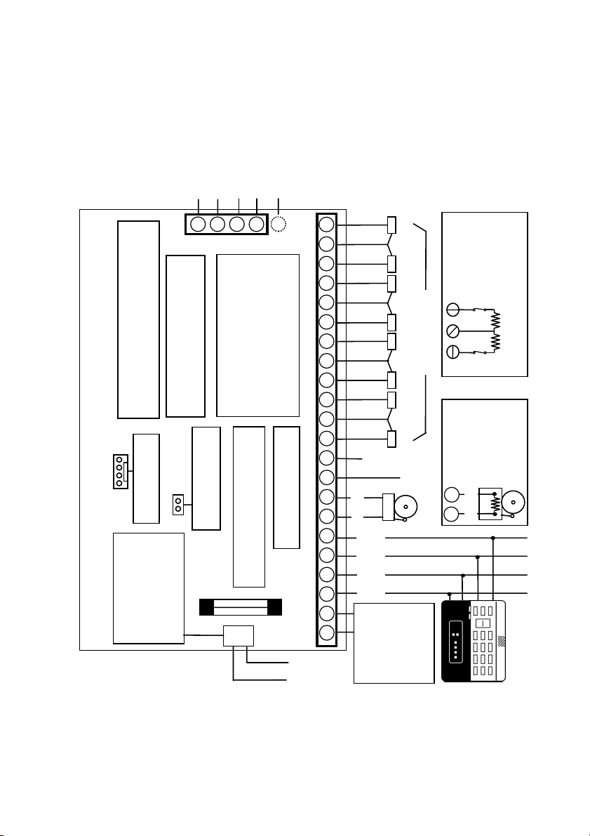
2.2: Wiring Diagram
J4
Household Burglary Alarm Panel
Electronics Line (E.L.) recommends testing
AUXILI ARY PO WER OUT PU T:
the system at least once a week. Refer to the
testing procedure found in the user manual.
Electronics Line (E.L.) Ltd. – Penta Plus
Voice Module
Connector for 3601
12V/3.2Ah BATTERY:
Replace the battery
every 3 - 5 years.
The maximum charging
current is 350mA.
Line
Telephone
AUX OUTPUT CURRENT DRAW:
AC Operated: 13.5 - 14.0V
The auxiliary output current allowed
Battery Operated: 12V Nominal
default restore
JPD Jumper for factory
BATTERY PROTECTION FUSE:
+
2 3 4 5
for peripheral units must not exceed
300mA when one keypad is installed.
Replace with a 1.0A/250V fuse
-
Optional
1
For each additional keypad (up to 3
max.) the permitted current draw is
BELL/SIREN OUTPUT:
Earth
Connection
reduced by 50mA.
600mA max.
J1
B L A C K
R E D
Connections
hardware
(EOLR)
W
/
2.2K
1
W
/
2.2K
1
only)
LED Keypad
ML0090A (10/01)
4
4
22
21
20
19
18
17
16
15
14
13
12
11
10
9
-
8
7
+
6
5
4
3
2
1
Z8 Z7
Z6
Z5
Z4 Z3
ZONE
CONNECTIONS
Z2
Z1
Zone
Tamper
PGM
KPD
K2 K1
-
AUX
+
15VAC
50/60Hz
22-30VA
AC Transformer
Do not connect to
a switch controlled
receptacle.
Zone
of Line
Resistor
Typical End
N.C.
N.C.
Bell
(USA
Supervised
Connections
-
8
2.2K
7
+
-7-
g
2.3: Terminal Connections
15-16.5VAC Input
(J1) Terminals 1 & 2: Connect a 15VAC transformer rated at 22-30VA, using 18 AWG wire.
Auxiliary Power Output
(J1) Terminals 3(+), 4(-): The auxiliary power output connections supply power to
keypads and peripheral units such as detectors and other powered sensors.
Keypad Data Bus Connections
(J1) Terminals 5 & 6: Connect up to three individually addressed LED keypads to
terminals 5 (K2), and 6 (K1). Make sure that the wires are connected to the same
connections on the keypad – see 2.4: Mounting the Keypad.
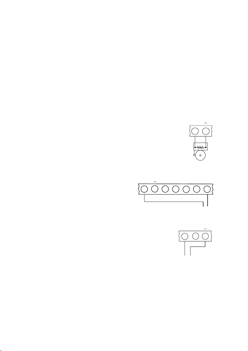
Bell Power Output
(J1) Terminals 7(+), 8(-): Connect these terminals to supply
+
7 8
power to the bell. The bell power output supplies AUX power,
rated at 600mA max.
Bell Supervision (USA hardware only)
The bell connections must be terminated by a 2.2K ¼W resistor
as shown in Figure 2.1.
PGM Programmable Output
(J1) Terminal 9: The PGM output switches
AUX
+
37485
Supervision Connections
6
2.2K
Figure 2.1: Bell
PGM
to ground when activated, enabling the
connection of additional system status
indicators. Connect the PGM output as
shown in the Figure 2.2.
ure 2.2: PGM Output Connections
Fi
Tamper Zone/Keyswitch Connections
(J1) Terminal 10: Connect a tamper switch or ON/OFF
LOAD
(100mA max.)
+
10 11 12
keyswitch to terminals 10(+) and 12(-). Note: If neither the
tamper zone nor keyswitch are used, short terminal 10 to
12 and define this zone as Tamper Zone at Address 01.
Zone Connections
Tamper Switch or
ON/OFF Keyswitch
Figure 2.3: Tamper Zone/
Keyswitch Connections
(J1) Terminals 11, 12, 13, 14, 15, 16, 17, 18, 19, 20, 21 & 22:
ZONE 1: Terminals 11(+) & 12(-) ZONE 5: Terminals 17(+) & 18(-)
ZONE 2: Terminals 13(+) & 12(-) ZONE 6: Terminals 19(+) & 18(-)
ZONE 3: Terminals 14(+) & 15(-) ZONE 7: Terminals 20(+) & 21(-)
ZONE 4: Terminals 16(+) & 15(-) ZONE 8: Terminals 22(+) & 21(-)
9
-8-
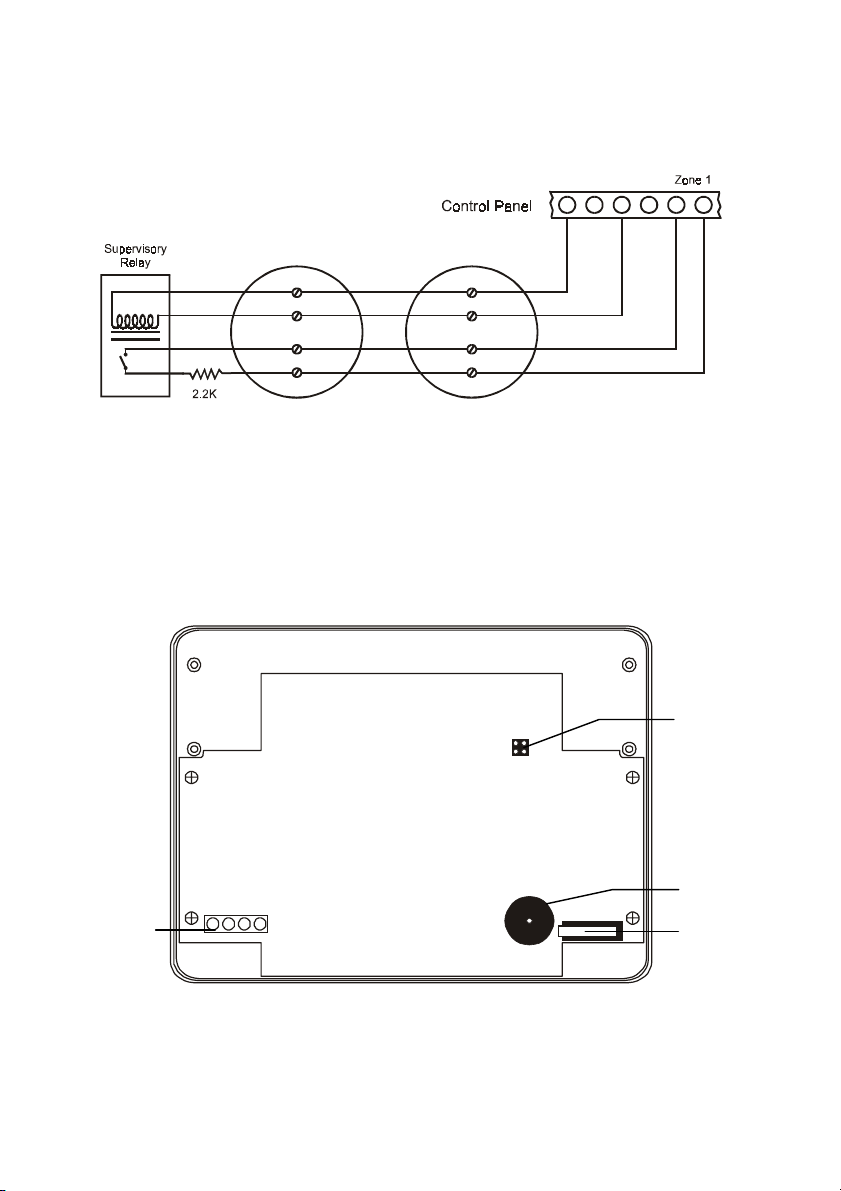
Fire Zone Connections
When Zone 1 is defined as Fire, connect four-wire smoke detectors as shown below in
Figure 2.4.
+12V
789101112
Figure 2.4: Four-wire Smoke Detector Connections (Zone 1)
Telephone Line
(J4) Terminals 1, 2, 3, 4 & 5: The telephone line should be connected (using the
standard Telco wires - minimum 26 AWG) as follows: 1 - Earth, 2 - Home Tip, 3 - Home
Ring, 4 - Telco Tip and 5 - Telco Ring.
2.4: Mounting the Keypad
Configuration
Jumpers
Buzzer
Tamper
Switch
Terminal
Block
AB
1234
Figure 2.5: 3104 Plus LED Keypad (cover removed)
-9-
Up to 3 LED keypads can be connected to the Penta Plus control panel. To mount the
keypad:
1. Separate the front and back cover of the keypad by pressing the locking tabs,
situated at the bottom of the keypad, with a small flathead screwdriver.
2. Pull the keypad wires through the opening in the back cover nearest the terminal
block and mount the back cover to the wall.
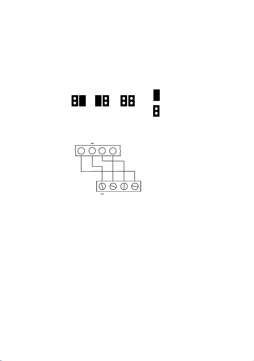
3. Define the keypad address by configuring jumpers A & B according to the following
diagram.
B A B A B A
Jumper
Installed
Keypad 3 Keypad 2 Keypad 1
Figure 2.6: Keypad Jumper Configuration
Jumper
Removed
4. Connect the keypad to the control panel according to the following diagram.
K1
+
3
K2
5
4
6
CONTROL PANEL
KEYPAD
K2
K1
Figure 2.7: Keypad Connections
+
5. Reassemble the front and back cover of the keypad.
2.5: Turning on the System
Once all of the systems components are properly connected to their destination terminals,
the Penta Plus is ready to be turned on. To avoid the risk of electrical shock or damage to
the control panel, make sure that both the AC supply and the battery are connected
properly before plugging in the system. If you experience any difficulties in applying power
to the unit, please contact Electronics Line’s Technical Support Department. The panel is
supplied with a default program that includes typical programming data which means that
minimum programming is required for typical installations.
To turn on the system:
1. Install the JPD jumper located at the top of the control panel board.
2. Reapply power and wait for 10 seconds; the keypad beeps to indicate the end of the
10 second period.
3. Disconnect both the AC and battery power supply.
4. Remove the JPD jumper.
5. Reapply power and wait for 10 seconds; the keypad beeps to indicate that the default
program has been restored.
The default settings can be reset at any time by disconnnecting the power supply and
repeating the above procedure.
-10-
 Loading...