

ektor 1808, 1809, 1810, 1811, 1812 Installation Instructions Manual
...
CODE: 1808, 1810, 1812, 1814
CODE: 1809, 1811, 1813, 1815
Installation Instructions
1808 EV-PEARL-EM-WP
1809 EV-PEARL-EM-PRO-WP
1810 EV-PEARL-WP
1811 EV-PEARL-PRO-WP
1812 EV-PEARL-EM-WP-S
1813 EV-PEARL-EM-PRO-WP-S
1814 EV-PEARL-WP-S
1815 EV-PEARL-PRO-WP-S
CONTENTS
Welcome
1.
Overview
2.
Safety warnings
3.
Installation
4.
Mounting
5.
Terminal block wiring
6.
Self-test wiring / central battery system
7.
DALI wiring / central battery system
8.
Using the inverter with a switch
9.
Using the inverter with a sensor
10.
Using the inverter with an onboard microwave sensor
11.
Maintaining your Circular Pearl luminaire
12.
Replacing the battery
13.
Battery life
14.
Power and battery charge
15.
Wireless daughterboard
16.
Non maintained / maintained jumper
17.
Discharge rating selection
18.
Onboard microwave sensor settings
19.
Accessories list
20.
Self-test indicator LEDs
21.
Self-test / commissioning interval programming
22.
Product specifications
23.
Australian emergency classification
24.
Spacing table
25.
Construction sites
26.
Testing precautions
27.
Problem solving procedure
28.
Warranty information
29.
Compliance standards
30.
Technical support and troubleshooting
31.
MANUFACTURED
TO ISO9001
1. WELCOME
Thank you for choosing this quality Ektor product.
This manual is intended to help you install this
product in a way that ensures the safety of yourself
and others. Whilst this Ektor product is designed
to be installed easily, we highly recommend you
take the time to read this manual thoroughly before
commencing installation. When installed correctly
and serviced regularly, this product will provide
hassle free operation for many years.
1

CIRCULAR PEARL EMERGENCY INSTALLATION INSTRUCTIONS
2. OVERVIEW
Ektor Generation III platform introduces you to a new era of emergency lighting control. With years in the
making, the third generation platform builds on the Ektor product ranges’ increasing quality, reliability and
performance. In choosing this Ektor product you can be comfortable that you have the best.
This product out of the box can be wired in any of these configurations:
• Self testing unit
• Standalone unit
• Standalone unit controlled with a switch or sensor
• DALI controlled remote testing unit
And can be used with a central battery system (monitored and non-monitored)
An optional wireless module can be added to allow you to connect to standard Wi-Fi networks for remote
testing and reporting.
Our Ektor Generation III platform also brings class leading technology which increases performance and
reliability including:
• Smart battery charging technology which reduces power consumption up to 90% while
increasing the service life of the battery
• Smart battery conditioning to ensure the best performance from the battery
• 450V Electrolytic capacitors which increase the products reliability
• Highly efficient design to reduce fatigue on the product
For buildings requiring longer durations such as 3, 4 and 8 hours the installer can change the jumpers found
on the unit for automatic scaling of the output.
3. SAFETY WARNINGS
1. THIS PRODUCT MUST ONLY BE INSTALLED BY A LICENSED ELECTRICIAN.
2. BEFORE COMMENCING INSTALLATION TURN OFF AND ISOLATE THE ELECTRICAL SUPPLY.
3. DO NOT ENERGISE WITH PRODUCT OPEN OR DISASSEMBLED.
4. SUPPLY VOLTAGES WITHIN PRODUCT. ISOLATE SUPPLY VOLTAGES BEFORE OPENING OR SERVICING.
5. THE ONLY USER SERVICEABLE PART IS THE BATTERY PACK.
6. DO NOT ATTEMPT TO SERVICE OTHER PARTS OF THE FITTING AS THIS WILL VOID THE WARRANTY.
7. AS THE INSTALLER, IT IS YOUR RESPONSIBILITY TO ENSURE YOU COMPLY TO ALL RELEVANT BUILDING AND SAFETY
CODES FOR EXAMPLE THE BCA, AS3000. REFER TO APPLICATION STANDARDS FOR THE RELEVANT RULES.
8. WHEN THE INSTALLATION IS COMPLETE, LEAVE THIS MANUAL WITH THE BUILDING’S OWNER(S) FOR FUTURE REFERENCE.
2
CIRCULAR PEARL EMERGENCY INSTALLATION INSTRUCTIONS
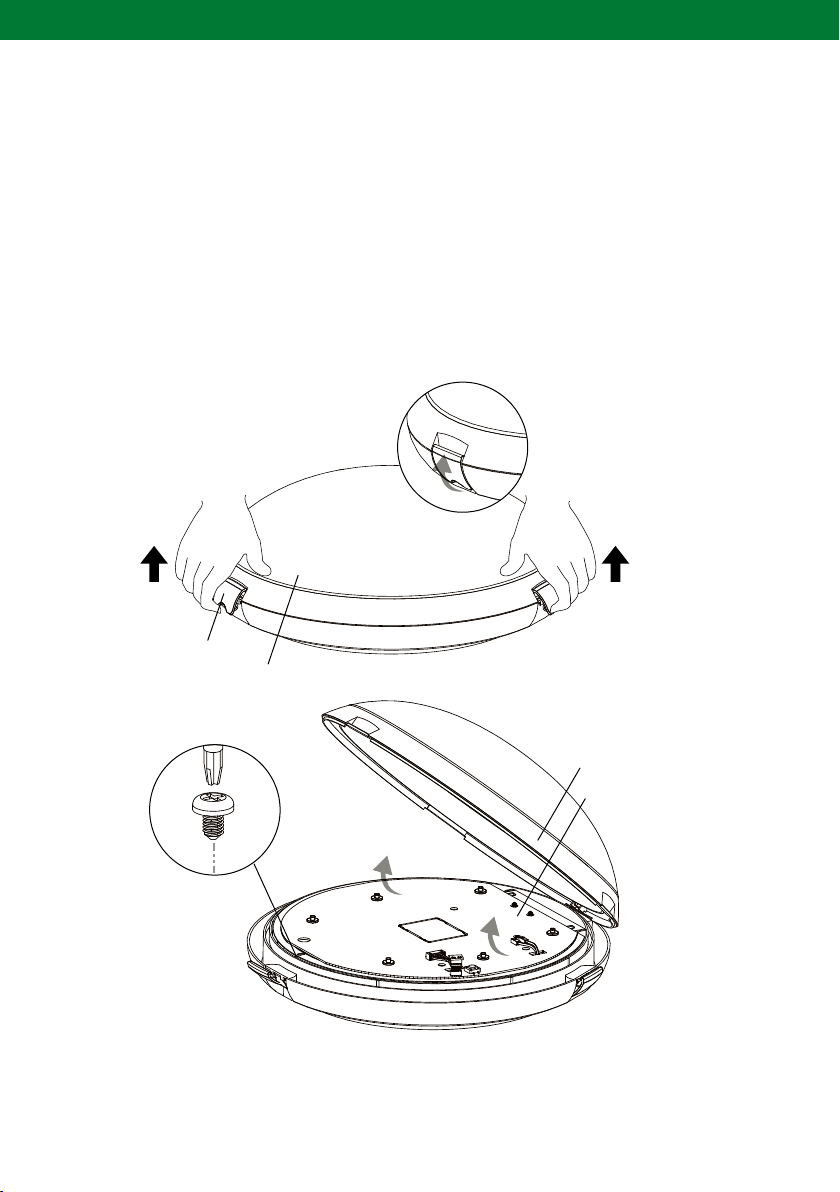
4. INSTALLATION
The Ektor Weatherproof Circular can be installed by mounting the product to the ceiling. To install the
Circular please follow the steps listed below:
1. Remove the product from the box and inspect it for any damage. If you believe the product to be
damaged or otherwise unsound, DO NOT install the product. Please pack it back into its box and return
it to the place of purchase for replacement. If the product is satisfactory, proceed with the installation.
2. When mounted the Circular cover MUST be opened. Open the cover by releasing the clasps and swing
the cover upwards by its hinge as shown below. This will allow for the gear tray to become visible.
3. Locate the screw(s) holding the gear tray in place, unscrew it and swing the gear tray upwards.
4. The cover is to be released for mounting the Circular, battery replacement and servicing.
Clasps
Circular cover
NOTE: No tools should be
used to release the clasps
Circular cover
Gear tray
Figure 1: Circular installation
3
CIRCULAR PEARL EMERGENCY INSTALLATION INSTRUCTIONS
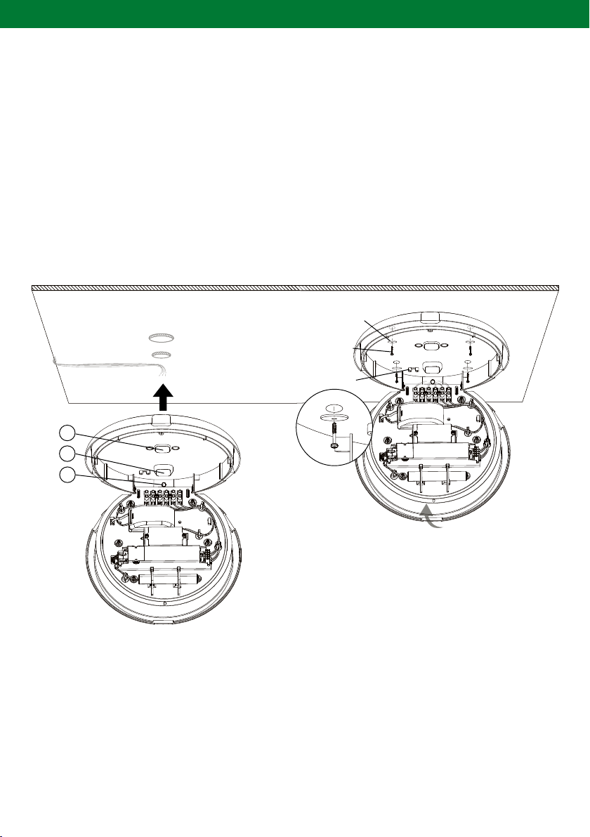
5. MOUNTING
CEILING MOUNT
Before you start mounting your Circular, the access point for the terminal block wiring must be chosen.
There are three different access points(A, B, C), option C is specificaly for conduit entry.
1. Drill a hole through the Circular base in the desired position. Route the wiring for the terminal block
through the holes and the supplied weatherproof gland.
2. Move the Circular into position on the ceiling and mount by fastening the screws securely to the flat
surface with the use of the supplied washers.
3. Wire the terminal block as shown in section 6 (page 5), tighten cables into the strain relief and
reassemble cover as in steps 2 and 3.
Washers
supplied
6 gage screws
not supplied
Strain relief
A
B
C
NOTE: Optional maisonary anchors/raw plugs are supplied
Figure 2: Ceiling mount
4
CIRCULAR PEARL EMERGENCY INSTALLATION INSTRUCTIONS
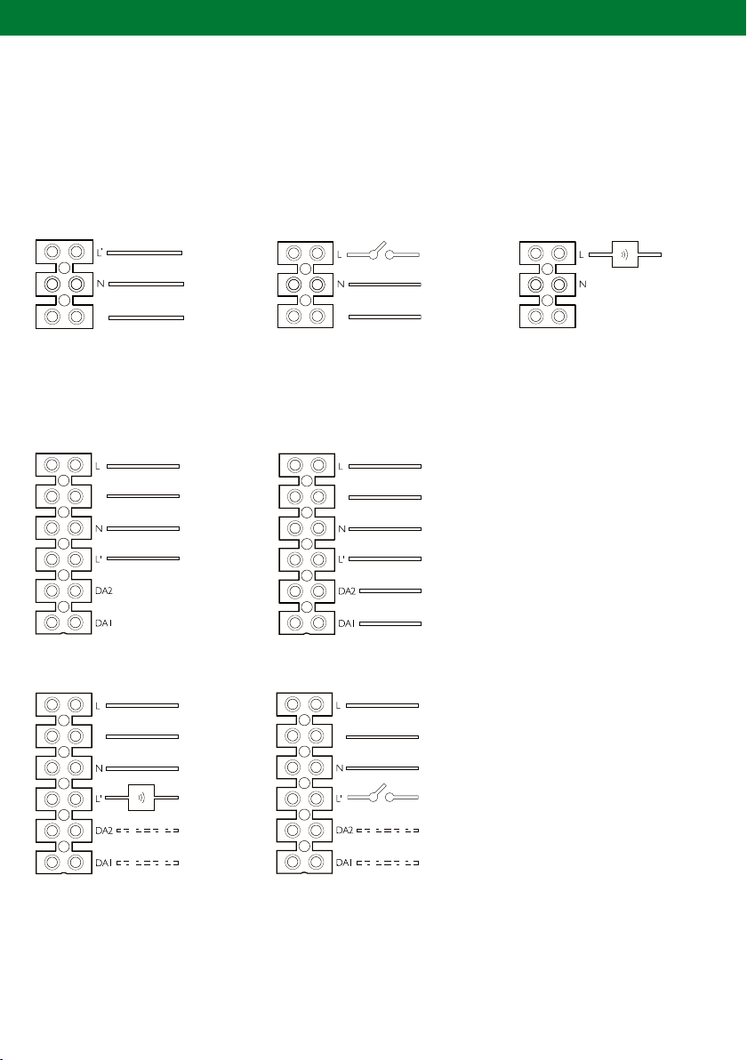
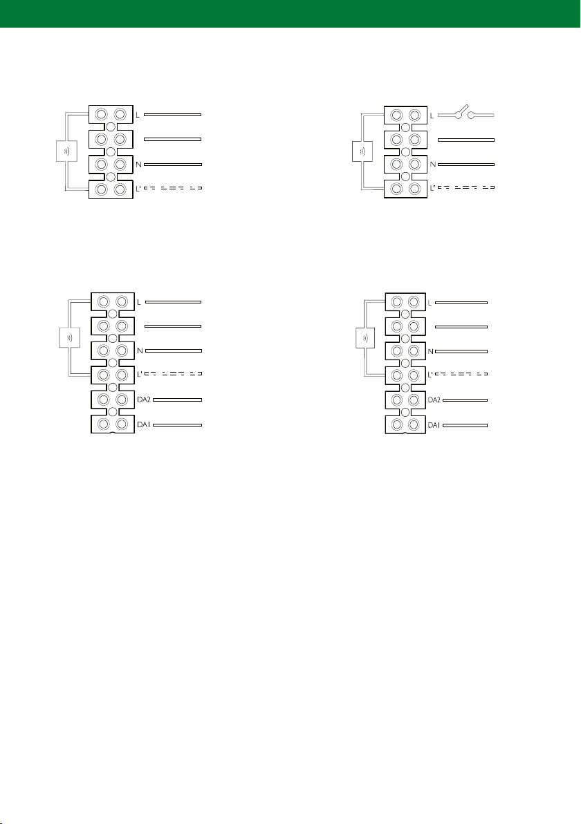
6. TERMINAL BLOCK WIRING OPTIONS
The wiring for Circular differs between models and accessories installed. Wiring schematics for the terminal
blocks used with the Circulars in the following sections.
EV-PEARL & EV-PEARL-PRO
Switched
Standard
External sensor
E
Figure 3:
E
Mains operation only
EV-PEARL-EM & EV-PEAR-EM-PRO
Standard DALI emergency
E
External switchExternal sensor
E
Optional Optional
E
E
E
Unswitched activeUnswitched active
ActiveActive
Optional Optional
Figure 4:
Emergency models
5
CIRCULAR PEARL EMERGENCY INSTALLATION INSTRUCTIONS
E
EV-PEARL-S & EV-PEAR-PRO-S
Standard Switched
Internal
sensor
E
Sensor out
Optional
Figure 5:
Microwave models
Internal
sensor
E
Sensor out
Optional
EV-PEARL-EM-S & EV-PEAR-EM-PRO-S
Standard DALI emergency
Combined input
Internal
sensor
E
Sensor out
Optional
Figure 6: Emergency
7. SELF-TEST/ STANDARD WIRING/ CENTRAL BATTERY SYSTEM
In emergency models the inverter can be used in an automatic self-test mode which reduces the need for a test
switch timer.The self-test ability automatically disables if the unit is wired to DALI or the wireless daughterboard
is attached. Additionally the third generation platform can be wired to a central battery system. With this wiring
the system cannot report the light status (see Self test support document for more information).
Internal
sensor
Sensor out
Optional
microwave models
8. DALI WIRING/ CENTRAL BATTERY SYSTEM
The Circular inverter supports DALI out of the box, illustrated in the hardwiring diagram
shown below. The inverter also supports central battery systems and can be monitored through DALI. When
used as a central battery system the devices can be tested with DALI. See wiring diagram in section 6 (page 5).
NOTE: Emergency models with microwave sensors do not support central battery as regular and emergency power is not separated.
6
 Loading...