

ektor 03135 EV-MERCURY, 03136 EV-MERCURY-B Installation Instructions Manual
CODE: 03135
CODE: 03136
Installation Instructions
03135 EV-MERCURY
03136 EV-MERCURY-B
CONTENTS
1. Welcome
2. Overview
3. Safety warnings
4. Installation
5. Mounting options
6. Terminal block wiring
7. Maintaining your Mercury exit sign
8. Replacing the battery
9. Battery life
10. Power and battery charge
11. Wireless daughterboard
12. Self test / standard wiring/ central battery system
13. DALI wiring / central battery system
14. Using the inverter with a switch
15. Accessories list
16. Non maintained / maintained jumper
17. Discharge rating selection
18. Self test indicator LEDs
19. Self test / commissioning interval programming
20. Product specifications
21. Spacing table
22. Australian emergency classification
23. Construction sites
24. Testing precautions
25. Warranty information
26. Problem solving procedure
27. Compliance standards
28. Technical support and troubleshooting
MANUFACTURED
TO ISO9001
1. WELCOME
Thank you for choosing this quality Ektor
product. This manual is intended to help you
install this product in a way that ensures the
safety of yourself and others. Whilst this Ektor
product is designed to be installed easily, we
highly recommend you take the time to read
this manual thoroughly before commencing
installation. When installed correctly and serviced
regularly, this product will provide hassle free
operation for many years.
1

MERCURY EMERGENCY INSTALLATION INSTRUCTIONS
2. OVERVIEW
Ektor Generation III platform introduces you to a new era of emergency lighting control. With years in the
making, the third generation platform builds on the Ektor product ranges’ increasing quality, reliability and
performance. In choosing this Ektor product you can be comfortable that you have the best.
This product out of the box can be wired in any of these configurations:
• Self testing unit
• Standalone unit
• Standalone unit controlled with a switch or sensor
• DALI controlled remote testing unit
And can be used with a central battery system (monitored and non-monitored)
An optional wireless module can be added to allow you to connect to standard Wi-Fi networks for remote
testing and reporting.
Our Ektor Generation III platform also brings class leading technology which increases performance and
reliability including:
• Smart battery charging technology which reduces power consumption up to 90% while
increasing the service life of the battery
• Smart battery conditioning to ensure the best performance from the battery
• 450V Electrolytic capacitors which increase the products reliability
• Highly efficient design to reduce fatigue on the product
For buildings requiring longer durations such as 3 or 4 hours, the installer can change the jumpers found
on the unit for automatic scaling of the output. Moreover should you require non-maintained or maintained
output, the installer can select this on installation.
3. SAFETY WARNING
1. THIS PRODUCT MUST ONLY BE INSTALLED BY A LICENSED ELECTRICIAN.
2. BEFORE COMMENCING INSTALLATION TURN OFF AND ISOLATE THE ELECTRICAL SUPPLY.
3. DO NOT ENERGISE WITH PRODUCT OPEN OR DISASSEMBLED.
4. SUPPLY VOLTAGES WITHIN PRODUCT. ISOLATE SUPPLY VOLTAGES BEFORE OPENING OR SERVICING.
5. THE ONLY USER SERVICEABLE PART IS THE BATTERY PACK.
6. DO NOT ATTEMPT TO SERVICE OTHER PARTS OF THE FITTING AS THIS WILL VOID THE WARRANTY.
7. AS THE INSTALLER, IT IS YOUR RESPONSIBILITY TO ENSURE YOU COMPLY TO ALL RELEVANT BUILDING AND SAFETY
CODES FOR EXAMPLE THE BCA, AS3000. REFER TO APPLICATION STANDARDS FOR THE RELEVANT RULES.
8. WHEN THE INSTALLATION IS COMPLETE, LEAVE THIS MANUAL WITH THE BUILDING’S OWNER(S) FOR FUTURE REFERENCE.
2
MERCURY EMERGENCY INSTALLATION INSTRUCTIONS
4. INSTALLATION
Ektor Mercury emergency installation varies depending on which product is chosen; the Mercury or the
Mercury IP65 Case. To install the Mercury emergency please follow the steps listed below:
1. Remove the product from the box and inspect it for any damage. If you believe the product to be
damaged or otherwise unsound, DO NOT install the product. Please pack it back into its box and return
it to the place of purchase for replacement. If the product is satisfactory, proceed with the installation.
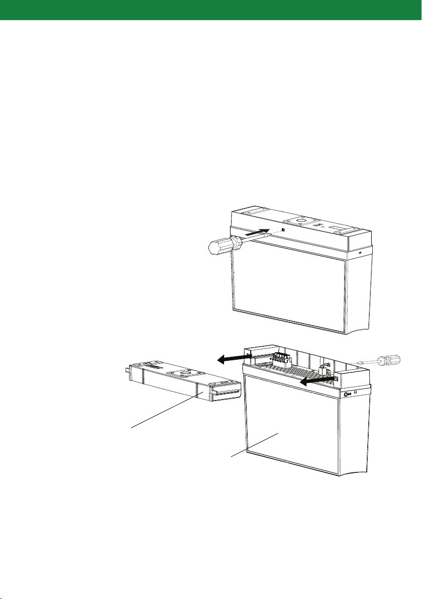
2. Remove the cover using a flat blade screwdriver to release the clip by pushing in and down as shown
below. The Mercury top cover can then be removed by sliding it away from the screwdriver.
The cover MUST BE mounted prior to attaching to the Mercury body.
3. The product can be a suspended or surface mount. All installation options can be found in the following
section of this manual.
NOTE: Ensure the Mercury clip is released
with a flat blade screwdriver (<6 mm) before
attempting to remove.
Cover
Mercury body
Figure 1: Mercury disassembly for ceiling installation
3
MERCURY EMERGENCY INSTALLATION INSTRUCTIONS
5. MOUNTING OPTIONS
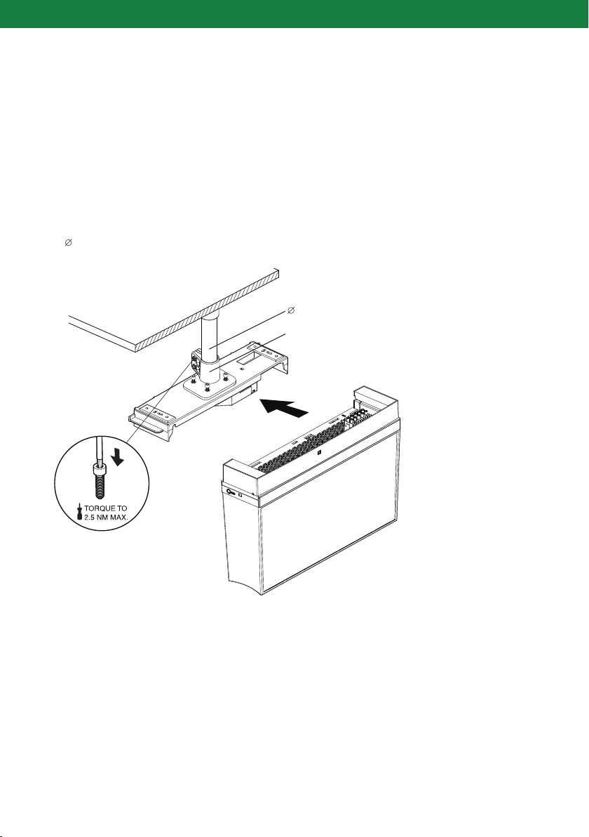
ROD MOUNT
Refer to 1990 EV-RODMOUNT Installation guide included in rod mount kit. The product and rod MUST BE
dry and clean before assembly to avoid joint contamination.
1. Disassemble the Mercury as shown in the disassembly instructions in section 4 (page 3) of this manual.
This will allow for the rod mount to be assembled to the products top cover.
2. Ensure rod is mounted ONLY on a flat surface and fasten with the appropriate fixing i.e. masonry anchor
for concrete.
3. A 25 tube is to be used, pushed firmly on both ends and fastened with M5 cap screws and locknuts.
25 tube
Rod mount
NOTE: DO NOT over tighten
screws when mounting the rod
mount to the Mercury.
The rod mount is suitable with
tubes ranging from 0-2 metres in
length. Weight on the rod must
not exceed 8kg.
M5 cap screw/
locknut detail
Figure 2: Mercury rod mount installation
4
MERCURY EMERGENCY INSTALLATION INSTRUCTIONS
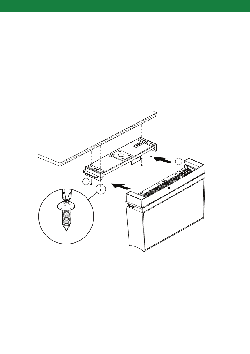
SURFACE MOUNT
The surface mount cover must be fastened to the ceiling first. Once the cover has been securely mounted
the Mercury may be assembled by sliding the Mercury body into place.
1. Disassemble the Mercury as shown in the disassembly instructions in section 4 (page 3) of this manual.
This will allow for access to mounting holes in the products top cover.
2. The top lid of the Mercury is to be mounted first by fastening screws into position. The screw positioning
can be seen in figure 3 (A).
3. Once the lid has been securely mounted the Mercury may be assembled by sliding the Mercury body
into place(B).
B
M4
A
Figure 3: Mercury surface mount installation
5
MERCURY EMERGENCY INSTALLATION INSTRUCTIONS
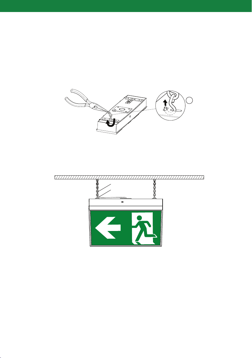
JACK CHAIN MOUNT
1. When using a jack chain for mounting, ensure the suitable thickness of 2.5mm chain is used for this product.
2. The surface cover must be threaded with the chain first before assembly of the Mercury.
3. Using pliers clamp the jack chain and thread through the Mercury as shown in figure 4 (A).
A
Jack chain
Cable
NOTE: Once the cover has been
chain mounted the Mercury
can be assembled.
Ensure the cable is secured onto
the jack chain and that there is no
strain or tension on the cabling.
(as shown in figure 4).
Figure 4: Jack chain installation
6
 Loading...