

Eko-Vimar Orlan, ORLAN 18, ORLAN 25, ORLAN 40, ORLAN 60 Installation, Operation And Maintanance Manual
...
Installation, Operation
And Maintenance Manual
Wood gasification boilers from 18-80 kW (85-275
kBtu)
O
rlan
®
ISO
9001
Often copied but never duplicated

EKO BOILER
MANU
AL
2
Table of Contents
Introduction and Important Information
Introduction............................................................................................................................................ 4
Wood Gasification ................................................................................................................................. 4
Cutaway Diagram and View of Gasification Flame ............................................................................... 5
Safety .................................................................................................................................................... 6
System Design and Installation
Chimney Requirements and Diagram ................................................................................................... 6
Hot Water Storage ................................................................................................................................. 7
Protecting the Boiler During Pump and Electrical Failures.................................................................... 7
Other Boiler Protection Considerations ................................................................................................. 7
The Importance of Boiler Placement and Location ............................................................................... 8
The Role of Cumbustion Air .................................................................................................................. 8
Packing List ........................................................................................................................................... 9
Boiler Setup ........................................................................................................................................... 9
Piping .................................................................................................................................................... 9
Four-Way Mixing Valve........................................................................................................................ 10
Gravity Overheat Protection Diagram ..................................................................................................11
Incorporating Hot Water Storage Diagram ...........................................................................................11
Various Other Piping Possibilities ........................................................................................................ 12
Filling the Boiler and Heating System ................................................................................................. 13
Connecting a Pump and Room Thermostat to the Controller.............................................................. 13
Controller Features, Specifications and Operation
Controller Features.............................................................................................................................. 14
Controller Functions ............................................................................................................................ 14
How the Controller Works.................................................................................................................... 15
Operating Your Boiler
Before You Begin................................................................................................................................. 16
Wood Fuel Considerations .................................................................................................................. 16
Starting and Operating the Boiler for the First Time ............................................................................ 17
Boiler Shutdown .................................................................................................................................. 18
Operating Temperature........................................................................................................................ 18
Primary, Secondary and Blower Air Inlet Settings ............................................................................... 18
Air Adjustment Guide........................................................................................................................... 18
What the Air Controls Do ..................................................................................................................... 19
Maintaining Your Boiler
General Maintenance .......................................................................................................................... 20
Standard Cleaning Tools ..................................................................................................................... 20
Fan Maintenance................................................................................................................................. 20
Routine Cleaning During the Heating Season..................................................................................... 20
EKO Super 1 Heat Exchanger Tubes.................................................................................................. 20
Cleaning the EKO Standard Heat Exchanger Tubes .......................................................................... 20
Maintaining Tight Seals ....................................................................................................................... 20
Offseason Preparation......................................................................................................................... 21

EKO BOILER
MANU
AL
3
Troubleshooting
Troubleshooting Guide ........................................................................................................................ 23
Technical Data
RK-2001UA Controller ......................................................................................................................... 25
Boiler ................................................................................................................................................... 26
Specifications and Dimensions ........................................................................................................... 27
Warranty
EKO Warranty ..................................................................................................................................... 28
Disposal and Recycling of Boiler Components
Notes on Proper Handling and Disposal of Boiler Components.......................................................... 29
EKO BOILER
MANU
AL
4
!
!
Introduction
And Important Information
Thank you for purchasing an Orlan EKO Wood Gasification boiler.
This boiler is designed to operate in the 91% to 95% overall system efficiency range when properly
installed and operated and burning sufficiently dry wood fuel.
The boiler has been independently tested and has been certified to conform to ISO 9001, TUV, CE.
Testing and certification for (North American certifications) UL 391, ETL and CSA are in progress.
As the owner you should familiarize yourself with the installation, operating and maintenance informa-
tion included in this manual. Be sure to save it for future reference especially since it contains your
warranty information.
Warning !
There are a number of these Warning Alerts throughout this manual. Be sure that you
read, understand and follow each of them.
Warning !
All systems should be designed and installed by a professional contractor and installer
experienced and qualified in hydronic (hot water) heating systems. Local and national
codes for solid fuel boilers must be followed.
EKO Line boilers are versatile, efficient and environmentally friendly:
• home heating and domestic water heating; can work together with other heating systems.
• high efficiency: less wood needed.
• clean burning: no visible smoke when fully operating; environmentally friendly.
• safer: clean burning results in little or no creosote buildup with minimal risk of a chimney fire.
Wood Gasification
Downdraft wood gasification boilers work by what is known as the “pyrolytic wood distillation” process. Dry wood is burned in the (top) primary combustion chamber, where heat from the flame breaks
the wood structure down into charcoal and eventually, into combustible gas. This gas passes through
the ceramic nozzle (or nozzles, depending on the model) at the bottom of the primary combustion
chamber, where it is mixed with superheated air and burned cleanly at high temperatures (up to
2,000 degrees F) in the refractory-lined bottom chamber. This clean-burning flame produces little or
no smoke. This hot gas then exits the boiler through the heat exchanger tubes and into the chimney.
Gas which was 2,000 degrees in the secondary chamber is typically only 300 to 400 degrees when
it reaches the chimney, meaning that 1,600 to 1,700 degrees is being transferred into the hot water
jacket through the heat exchanger tubes.
A clean-burning flame which sheds most of its heat on its way through the heat exchanger is the defi-
nition of a very efficient boiler.

EKO BOILER
MANU
AL
5
Two views of the gasification chamber and nozzle burning at near 2,000 degrees, F.
9
1
Important
Components
10
1.) Controller
2
2.) Loading Door
8
3.) Secondary Air Adjust
4.) Ash Door
6
5.) Forced Draft Fan
6.) Primary Burn Chamber
7.) Secondary Chamber
8.) Heat Exchanger Tubes
9.) Supply Water Outlet
5
10.) Bypass Damper Lever
3
7
4
EKO BOILER
MANU
AL
6
!
Warning !
Attention to safety is critical in all phases of boiler system design, installation, operation
and maintenance.
Safety
You must keep safety in mind during the installation, operation and maintenance of your boiler and
heating system. During installation the boiler and some components may be heavy or sharp. During
operation the boiler and associated plumbing can be very hot which can cause burns or fires. The
proper methods need to be used while loading wood when the boiler is hot.
System Design
The plumbing diagrams in this manual are for basic information only and do not show all the valves,
vents, fittings, etc. that are normally included in a finished boiler installation, nor do they cover all possible installation options.
It is the responsibility of the installing contractor to see that all controls are installed, configured and
operating properly when the boiler installation is complete.
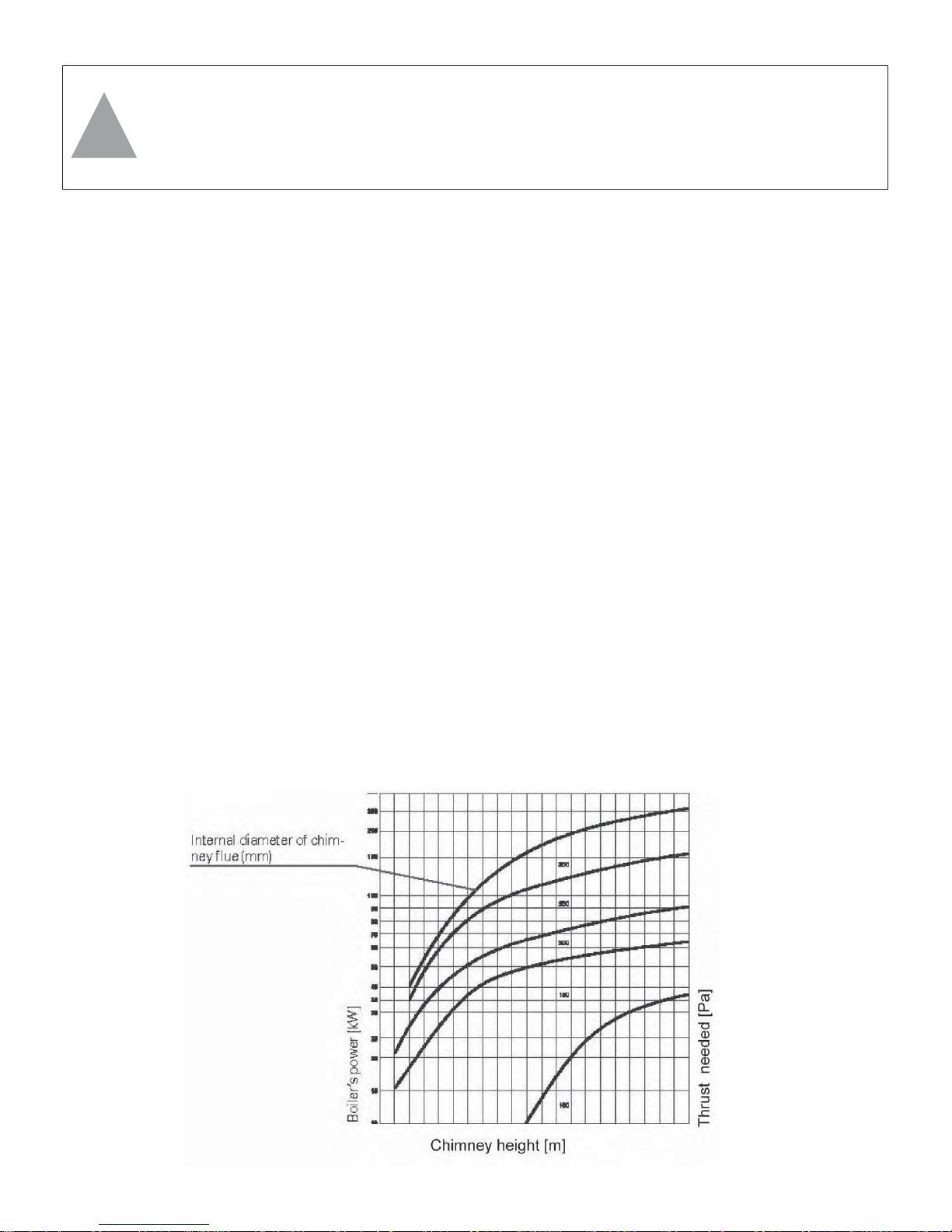
Chimney Specifications
The chimney or flue is one of the most critical factors in the successful operation of any solid fuel
heater, including your EKO Line boiler. A good chimney will provide a continuous and dependable
draft to pull the exhaust gases out of your boiler.The boiler must be connected to a tile-lined masonry
flue or to a Type HT approved chimney. Minimum required flue size is 8x8” with square tile or 8”
diameter round tile or stainless steel. No other appliance should be connected to this flue. The boiler
should be connected to the flue with the shortest, most direct run of black stove pipe. Maintain a minimum of 18” between the flue pipe and combustible surfaces. Prior to operation, the installation should
The chimney flue connected to the EKO boiler should conform to
the specifications specified below.
EKO BOILER
MANU
AL
7
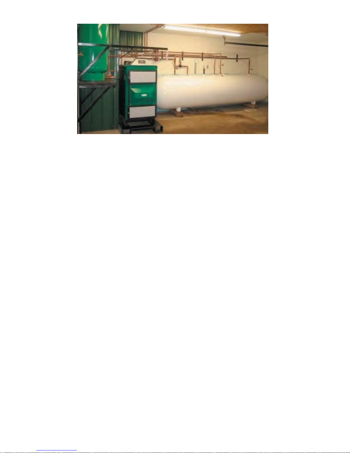
Expansion
Tank
1,000 Gallon
Hot Water Storage Tank
EKO 60 with 1,000 gallons of pressurized hot water storage and
expansion tank.
be inspected and approved by qualified professionals (i.e., a chimney sweep, a licensed plumbing
and heating contractor, electrician, etc.). Another important requirement is that the chimney and connecting pipe need to be insulated for safety and to prevent condensation and a reduction in the draft
caused when the gas in the chimney cools too much. If there is still a problem with draft (too much or
too little), draft inducing fans or draft regulators may need to be considered.
Hot Water Storage
For the best results, the use of a heat storage tank is recommended. A properly sized storage tank
can cut wood consumption by as much as 40%. Hot water storage allows the boiler to run at optimum
capacity regardless of the demand for heat from the building being heated. The stored heat can be
recovered later, both stretching the time between boiler re-fuelings, and as an additional source of
heat on very cold days. Generally, the bigger the storage tank the better, as the boiler is most efficient
when running at full capacity. The rule of thumb on tank sizing is that 13 gallons of water can store
about 1KW of boiler heat. Using the EKO 25 as an example: 13 gal/1KW x 31KW = 421 gallons, 421
gallons x 91% efficiency = 383 gallon minimum size water tank. A hot water storage tank connected to
an EKO boiler can also be used to store hot water from a solar water heater.
Protecting the Boiler During a Pump or Power Failure
During the course of operating the boiler, there is always the possibility of a pump or power failure. It
is recommended that you install an auxiliary power supply (i.e. UPS) to power the boiler fan, pumps
and controller during a power failure. It is also a good idea to install a gravity feed storage tank above
the boiler. Typically, this would be a water storage tank connected to a normally-closed zone valve (or
at a minimum, a manual valve) that will allow hot water from the boiler to circulate into the tank in the
event of a power outage.
Other Boiler Protection Considerations
• Do not use self-contained non-electric zone valves on the main heating zone as it is to be used as
the overheat/dump zone. Such a valve would prevent the overheat control from cooling the boiler
when necessary.
• Do not use any radiant floor heat tubing that does not have an oxygen barrier otherwise you must
use a heat exchanger between the hard piping of the boiler and the radiant floor heat tubing.
• A backup power supply such as a UPS (battery-based Uninterruptible Power Supply) is required
to operate the primary loop pump and dump zone valve if it is of the electrically operated variety. It
EKO BOILER
MANU
AL
8
is preferable to have a non-electric dump zone valve.
• A primary loop pump must feed all zones.
• Each boiler should be connected to the heating capacity which equals that of the boiler output.
• To protect the boiler against low-temperature corrosion the end-user should assure return temper-
ature does not reach lower than 120F. One way to do this is by installing a four-way mixing valve.
Installation
Orlan EKO boilers are designed to conform to and be installed in accordance with the stringent European regulations known as PN 87/B 02411 and PN 91/B-02413. When installed in the United States,
all applicable local codes and regulations should be observed.
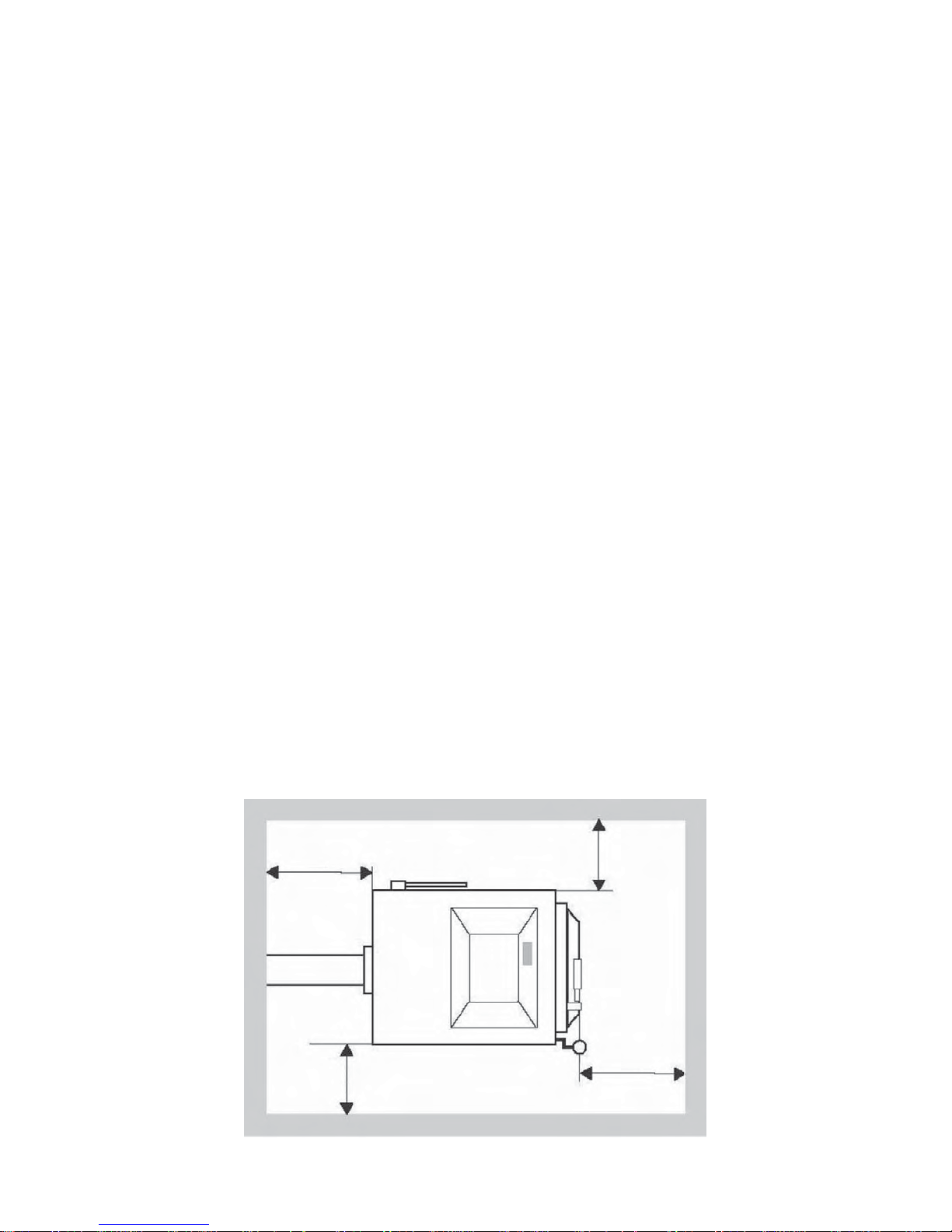
Location, Location, Location
You will need to have adequate room around the boiler for installation, operation, cleaning and maintenance. You will need plenty of room for loading the boiler and emptying the ash bin and room to
use the cleaning tools provided. You also need adequate clearances from combustibles. The distance
between the boiler and the surrounding walls should be sufficient to allow access to all of the boiler’s
parts, as specified in the clearance diagram below. The boiler must be positioned to provide minimal
clearances from combustibles and surfaces: Left and right side = 18,” top, rear and front = 36.”
The boiler can be placed in a utility room, basement or outbuilding, along with wood storage. Putting
the boiler in an outside location is recommended for easy access to wood storage, and to keep the
mess and flame out of the house.
The boiler must be located on a level concrete floor or an other non-flammable surface. Wood gasifi-
cation boilers are heavy; be sure to consider the weight when planning the installation.
Combustion Air
The boiler requires fresh air for combustion. It is critical not to starve the boiler of air, as the air supply
affects the quality of the burn as well as the strength of the chimney draft. If any fans are used in the
room where the boiler is located, they should be installed so as not to create negative pressure, i.e.,
they should not be pulling air from the room. Likewise, you do not want too much positive air pressure, as it can cause the boiler to burn out of control. You may need to pull outdoor combustion air
into the room if there are backdrafts, insufficient draft or improper combustion, among other problems.
You can easily check this by opening a window or door to see if the problem goes away.
36”
18”
18”
36” of headroom above the boiler
36”
Recommended clearances.

EKO BOILER
MANU
AL
9
Packing List
The complete EKO Orlan boiler is shipped from the warehouse in one crate.
Inside the crate you will find:
The boiler.
The cleaning tools (two or three, depending on the model).
Inside the boiler you will find:
This manual.
Refractory gasification bricks (two or more pieces that form a tunnel under the nozzle or nozzles).
Boiler Set-Up
The boiler is shipped completely assembled and ready for installation and use. The boiler should be
inspected inside and out for any defects or damage that may have occurred in shipping. After the
boiler is placed in its permanent location and before the first firing, the refractory tunnel will need to be
positioned directly under the nozzle or nozzles, so that the flame shoots directly down into the trough.
Piping
The direct connections to the boiler will be similar no matter which piping system you select (page
12). A detailed listing of pipe fittings, isolation valves, etc. is not part of this manual. If you have ques-
tions about designing your system, seek the advice of a hydronic heating professional.
However, some important piping considerations are included below:
A tee must be connected to the 2” NPT water inlet on the rear bottom of the boiler (return). In one port
of the tee install a drain valve that is piped to a floor drain. In the other port of the tee install a line to
the outlet of the circulating pump, upon which the inlet is connected to the outlet port of a 3- or 4-way
mixing valve. One inlet of the mixing valve is fed from the heat zone piping return lines. The other
inlet of the mixing valve is fed from a tee connected to the boiler outlet and the heat zone supply line.
The purpose of this valve is to prevent cold water from entering the boiler, which can result in thermal
shock causing mechanical warping and cracking, as well as creating condensation inside the firebox,
which will result in corrosion inside the boiler.
Connect another tee to the 2” NPT water outlet on the top of the boiler (supply). In one port of the tee
install the supplied pressure relief valve. Be sure to pipe the outlet of this valve with hard pipe (copper
or black iron) to within 6 inches of the floor, and be sure there are no shut-off valves or other obstructions on the pipe. When this relief valve opens, it means that the boiler pressure has reached or
exceeded 30 pounds per square inch. The steam and/or water released needs to flow freely and the
pipe must be no more than 6 inches from the floor to prevent injury to anyone nearby. In the other port
of the tee install a line to the tee connected to the boiler outlet and the heat zone supply line.
Connect a line from the building water supply through a back flow preventer valve to the boiler INLET
line. Water should only be introduced to the boiler when its temperature is below 160F.
There is a 3/4” NPT pipe sticking out each side of the boiler near the top. This is an emergency boiler
cooling system not used in North American installations. The outlets can be covered with 3/4” NPT
pipe caps with a 1/4” diameter hole drilled in each one. The caps cover the sharp threads and the
holes keep pressure from building up in the pipe during boiler operation. This system is independent
from the pressure vessel, so there is no boiler water involved.
 Loading...