

Eko-Vimar Orlan 18, Orlan 60, Orlan 25, Orlan 40, Orlan 80 Operating Manual
Orlan®
ISO 9001
Wood gasication boiler at 18- 80 kW
Operating manual

2
Contents
1. Boiler’s use. . . . . . . . . . . . . . . . . . . . . . . . . . . . . . . . . . . . . . . . . . . . . . . . . . . . . . . . . . . . . . . . . . . . . . 3
2. Procedure rule. . . . . . . . . . . . . . . . . . . . . . . . . . . . . . . . . . . . . . . . . . . . . . . . . . . . . . . . . . . . . . . . . . . 3
3. Installation . . . . . . . . . . . . . . . . . . . . . . . . . . . . . . . . . . . . . . . . . . . . . . . . . . . . . . . . . . . . . . . . . . . . . . 3
3.1. Diagram of chimney choice according to the DIN 4705 4 norm. . . . . . . . . . . . . . . 4
4. Regulator’s description . . . . . . . . . . . . . . . . . . . . . . . . . . . . . . . . . . . . . . . . . . . . . . . . . . . . . . . . . . . 5
4.1. Technical data of RK2001 regulator . . . . . . . . . . . . . . . . . . . . . . . . . . . . . . . . . . . . . . 5
4.2. Regulator system functions (RK2001). . . . . . . . . . . . . . . . . . . . . . . . . . . . . . . . . . . . . 6
4.3. Pump’s and room sensor’s connecting . . . . . . . . . . . . . . . . . . . . . . . . . . . . . . . . . . . 6
4.4. Front panel of regulator EKOSTER 2 . . . . . . . . . . . . . . . . . . . . . . . . . . . . . . . . . . . . . . 7
4.5. Technical data of the regulator EKOSTER 2 . . . . . . . . . . . . . . . . . . . . . . . . . . . . . . . 7
4.6. Function of EKOSTER 2 . . . . . . . . . . . . . . . . . . . . . . . . . . . . . . . . . . . . . . . . . . . . . . . . 8
5. Boiler’s technical data . . . . . . . . . . . . . . . . . . . . . . . . . . . . . . . . . . . . . . . . . . . . . . . . . . . . . . . . . . . 11
6. Connecting and exploitation. . . . . . . . . . . . . . . . . . . . . . . . . . . . . . . . . . . . . . . . . . . . . . . . . . . . . . 12
6.1. Connection. . . . . . . . . . . . . . . . . . . . . . . . . . . . . . . . . . . . . . . . . . . . . . . . . . . . . . . . . . . 12
6.2. Wood and gasication . . . . . . . . . . . . . . . . . . . . . . . . . . . . . . . . . . . . . . . . . . . . . . . . 12
6.3. Accumulation . . . . . . . . . . . . . . . . . . . . . . . . . . . . . . . . . . . . . . . . . . . . . . . . . . . . . . . . 14
6.4. Starting. . . . . . . . . . . . . . . . . . . . . . . . . . . . . . . . . . . . . . . . . . . . . . . . . . . . . . . . . . . . . .14
6.5. Burning up . . . . . . . . . . . . . . . . . . . . . . . . . . . . . . . . . . . . . . . . . . . . . . . . . . . . . . . . . . . 14
6.6. Fuel loading . . . . . . . . . . . . . . . . . . . . . . . . . . . . . . . . . . . . . . . . . . . . . . . . . . . . . . . . . . 15
6.7. Boiler’s putting out . . . . . . . . . . . . . . . . . . . . . . . . . . . . . . . . . . . . . . . . . . . . . . . . . . . . 15
6.8. Right boiler’s temperature assuring . . . . . . . . . . . . . . . . . . . . . . . . . . . . . . . . . . . . . 16
6.9. Power failure and pump’s breakdown . . . . . . . . . . . . . . . . . . . . . . . . . . . . . . . . . . . 16
7. Conservation . . . . . . . . . . . . . . . . . . . . . . . . . . . . . . . . . . . . . . . . . . . . . . . . . . . . . . . . . . . . . . . . . . . 17
7.1. Boiler’s conservation . . . . . . . . . . . . . . . . . . . . . . . . . . . . . . . . . . . . . . . . . . . . . . . . . . 17
7.2. Fan’s conservation . . . . . . . . . . . . . . . . . . . . . . . . . . . . . . . . . . . . . . . . . . . . . . . . . . . . 17
7.3. Boiler’s cleaning . . . . . . . . . . . . . . . . . . . . . . . . . . . . . . . . . . . . . . . . . . . . . . . . . . . . . . 17
7.4. Leakproof securing. . . . . . . . . . . . . . . . . . . . . . . . . . . . . . . . . . . . . . . . . . . . . . . . . . . . 18
8. Faults caused by boiler’s wrong exploitation . . . . . . . . . . . . . . . . . . . . . . . . . . . . . . . . . . . . . . . 19
9. Allowance for Orlan Super boilers. . . . . . . . . . . . . . . . . . . . . . . . . . . . . . . . . . . . . . . . . . . . . . . . .20
9.1. Cooling coil. . . . . . . . . . . . . . . . . . . . . . . . . . . . . . . . . . . . . . . . . . . . . . . . . . . . . . . . . . .20
9.2. Boilers’ cleaning . . . . . . . . . . . . . . . . . . . . . . . . . . . . . . . . . . . . . . . . . . . . . . . . . . . . . .20
10. Utilizing . . . . . . . . . . . . . . . . . . . . . . . . . . . . . . . . . . . . . . . . . . . . . . . . . . . . . . . . . . . . . . . . . . . . . . . 21
3
1. Boiler’s use
Wood is the main fuel for the Eko-Vimar Orlański boilers. Lignite or minced coil could be an alternative fuel.
Wood at 15-20% humidity and length at about 5 cm smaller than the loading chamber should be
used as the main fuel (billet’s diameter - 15-25 cm - check „technical data”).
Some alternative fuel is acceptable:
- lignite as 10-15 cm diameter blocks
- wood at different quality parameters (humidity) and mince range (shavings, furniture waste
and so on) is acceptable as the mix for the main fuel (50%/50%).
NOTICE!
Using different than ordinary fuel doesn’t guarantee boiler’s right operating - as it
was featured in technical data and it can inuence the boiler’s way of working and its
long-lasting.
NOTICE!
Using different type of fuel that the main one (including alternative one) is treated as
wrong boiler’s using and its effects can not be the reason for any complaint to the
producer.
NOTICE!
Wood boiler should be installed in open system together with an expansion tank (it
assures boiler’s working with nominal pressure - look “technical data”).
NOTICE!
Wood boiler is equipped with a regulator which assures its working in right temperature’s range and protects the boiler against its overheating by fan’s turning on.
2. Procedure rule
Wood gasication boilers work in pirolitic wood distillation process. When the air is limited
wood changes into charcoal while burning up. In the same time wood gas appears, which next
relocates to burner’s nozzle and there it is burnt at the bottom part of the boiler. Such method of
wood burning allow for its effective using as fuel. Orlan boilers are made for burning wood billets
(use minced wood only as an addition - it should be mixed with bigger wood parts as not to allow
for burner’s nozzle littering).
4
3. Installation
Wood boilers are to be installed according to the present norms and rules. The requirements of
norm PN 87/B 02411 according building of solid fuel boiler room and the norm PN-91/B-02413 according open system boilers’ producing should be taken into account.
Eko-Vimar Orlański company prescribes using chimney inputs which preserve against the
chimney permeating. The company doesn’t take responsibility in case of faults resulting from not
using chimney inputs.
1. Chimney ue should correspond to the parameters of „DIAGRAM OF CHIMNEY CHOSING
ACCORDING TO THE DIN 4705 NORM”.
2. Boiler room should be large enough to enable boiler’s cleaning (>2,2 m).
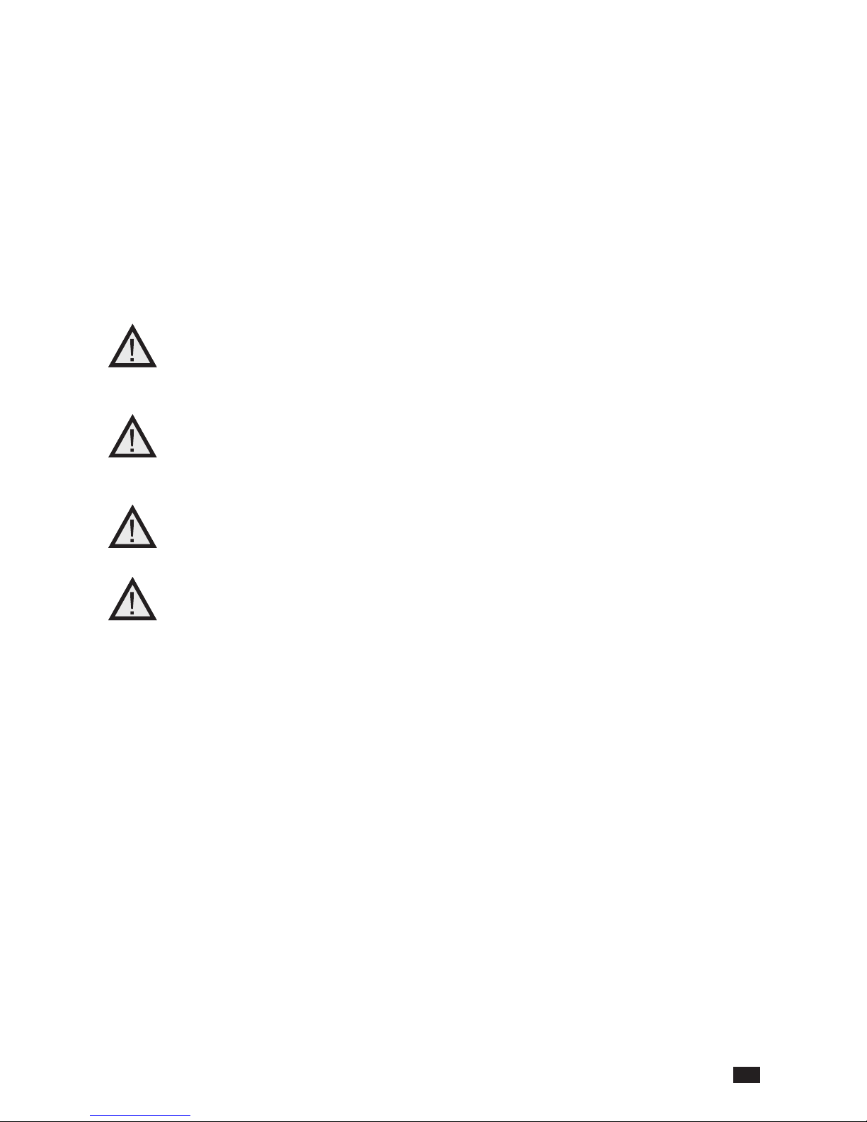
3. The distance between the boiler and the partitions should enable right access for all of the
boiler’s parts - it shouldn’t be less than - look at “Orlan boiler’s placing”.
Orlan boiler’s placing
4. There shouldn’t be any cables nor electric installations which aren’t for boiler’s room using.
Before smoke outlet’s connecting to the chimney ue, there should be a chimney sweep’s approval.
According to the PN-EN 303-5 norm accumulation tank should be assembled together with wood
boiler - its capacity is listed in reference to the . 4.2.5. point in the norm
5
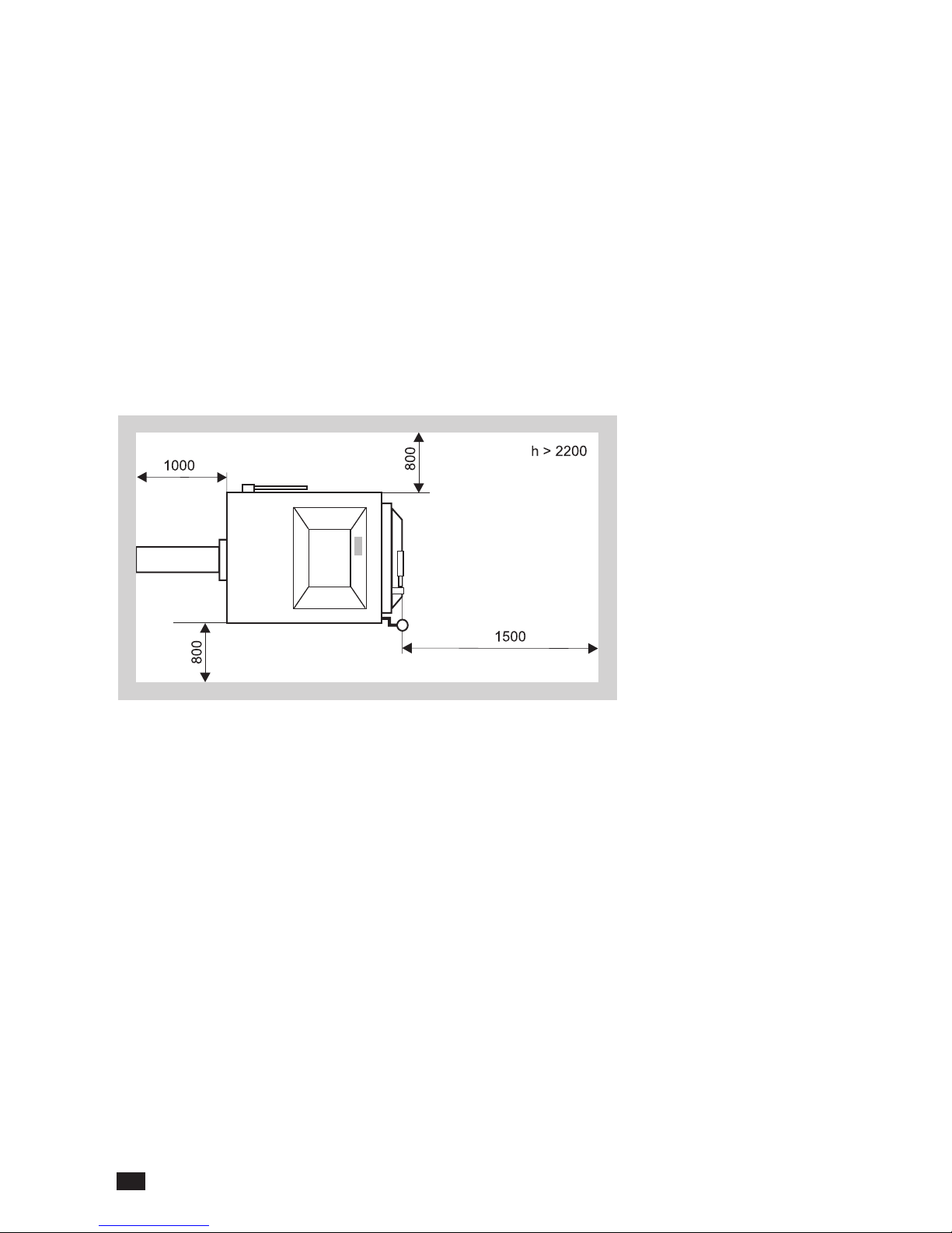
3.1. Diagram of chimney choice according to DIN 4705 norm
4. Regulator’s description
Since the 30.06.2006 wood boilers were equipped with RK 2001 regulator. In 01.07.2006 new
ones were brought out - EKOSTER 2. Main functions of both regulators are similar, but there is a
difference in parameters’ modication ( EKOSTER 2 ).
4.1. Technical data of RK 2001 regulator
Power 230V +/- 10%
Rate supply voltage (with no fan) < 4VA
Temperature measurement range 0 do 99 +/- 1 °C
Temperature measurement sensors
KTY 81 210
Temperature regulation range 60 - 80 °C
Electrical protection (fuse)
1A/220V
Boiler’s power [kW]
Internal diameter of chim-
ney ue (mm)
Thrust needed [Pa]
Chimney height [m]
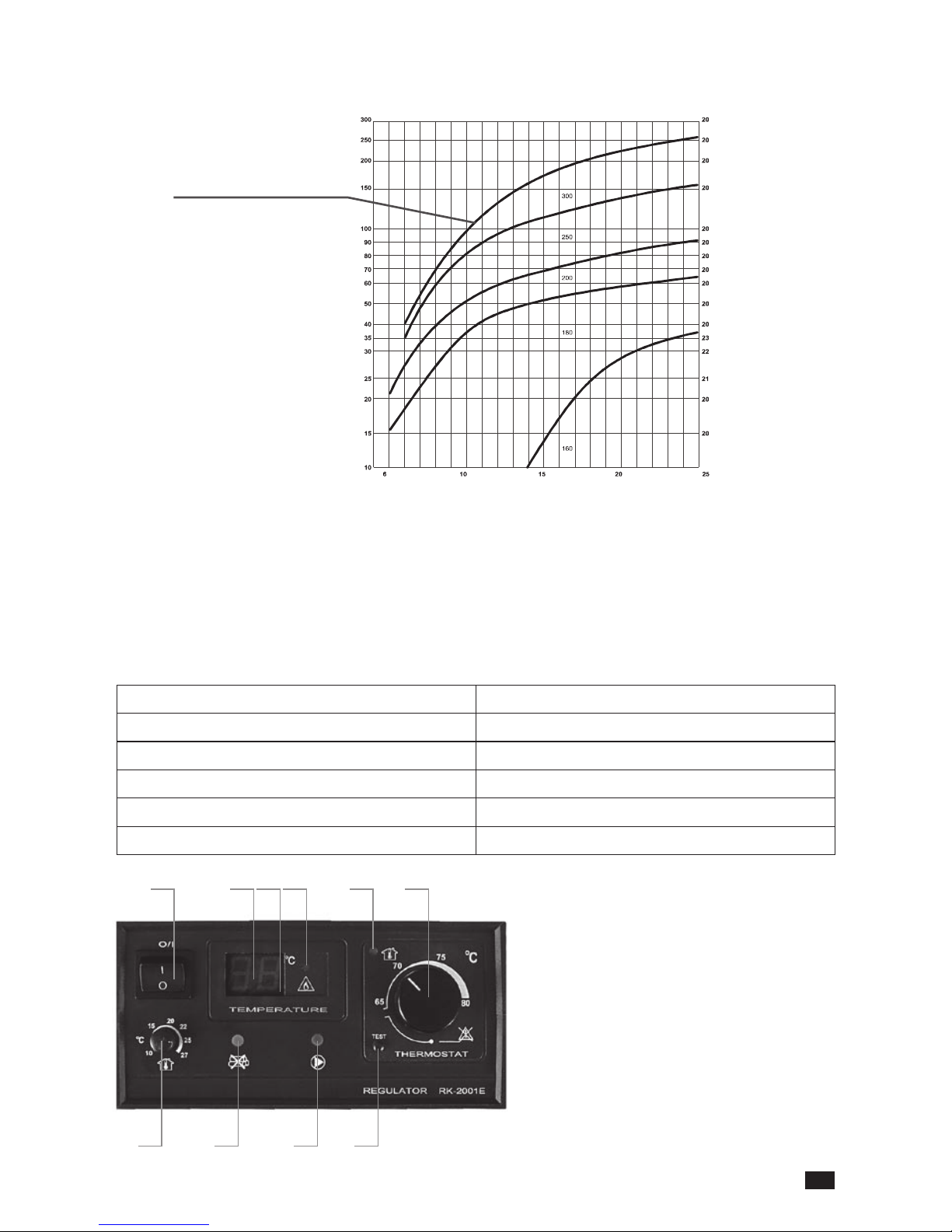
1. Power cut-out
2. Boiler’s temperature display
3. Burning up indicator
4. Overheating indicator
5. Room thermostat indicator
6. Boiler’s thermostat knob
7.
Pump’s operating indicator (the green one)
8. Fuel shortage indicator (the green one)
9. Room thermostat knob (the green one)
10. Boiler’s temperature setting test
Rys. 2 Front panel of the RK 2001 regulator
1 2 3 4 5 6
9 8 7 10
6
4.2. Regulator system functions (RK 2001)
Boiler’s temperature
setting at 60 up to
80°C
We set the boiler’s temperature with a knob (6). Current temperature is displayed on the
screen (2).
Boiler’s overheating
signalling
The indicator (4) tells about boiler’s temperature excees to 90°C. In the case the fan switches
off.
Lack of fuel signal
-
lisationl
If in 30 minutes temperature doesn’t reach 60°C, the indicator (8) and the fan will turn on.
Wrong burning up
signallization
If the boiler doesn’t reach 60°C during burning up (up to 2 hours) , the indicator (8) will light
up and the fan will turn off.
NOTICE
! In the case wood can remain in the boiler.
Fan’s operating
controlling
Regulator modulates fan’s operating and it upholds its depending on boiler’s temperature.
Pump’s operating
controlling
If pump is connected to regulator:
• while burning up pump is turned off till the time when boiler reaches 65°C
• when here is more than 65°C the pump still works till the time of temperature decreasing
(60°C) then it stops. Next time it activates when temperature reaches over 65°C
Room temperature
controlling
Boiler comes together with the sensor which can be placed in the room. Regulator control
with the boiler’s work in such a way that it keeps temperature needed in the room.
Cooperation with
room thermostat
Boiler can cooperate with any room thermostat* which should be connected instead of a
room thermostat
* NOTICE! If there is a room sensor or room thermostat connected to the boiler then
the boiler will stay in watching stage and then its continuous temperature is 60 - 65°C. If
temperature decreases under the needed one , boiler starts working again.
Scavenging Regulator can ush of the loading chamber in order to get rid of gathered wood gas. The
function activates while boiler’s lay over after reaching the temperature congurated. When
the boiler reaches the temperature 10% higher from the one setted on regulator, ushing
function will turn off till the time of the temperature’s decreasing to the level underneath.
Flushing time is 5 seconds , timing interval between next ushes depends on the regulator
settings and it is 1 up to 9 minutes.
NOTICE! Technical service should deal with ushing regulation.
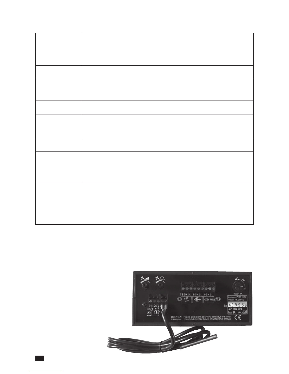
4.3. Pump’s and room sensor’s connecting
There is a connecting board at the back side of regulator where pump and room sensor can be
connected. The access for connecting board is possible only after the regulator’s disconnecting
and safety lid unscrewing. At the back panel there are some graphic markers and descriptions
featuring right elements’ connection placement.
7
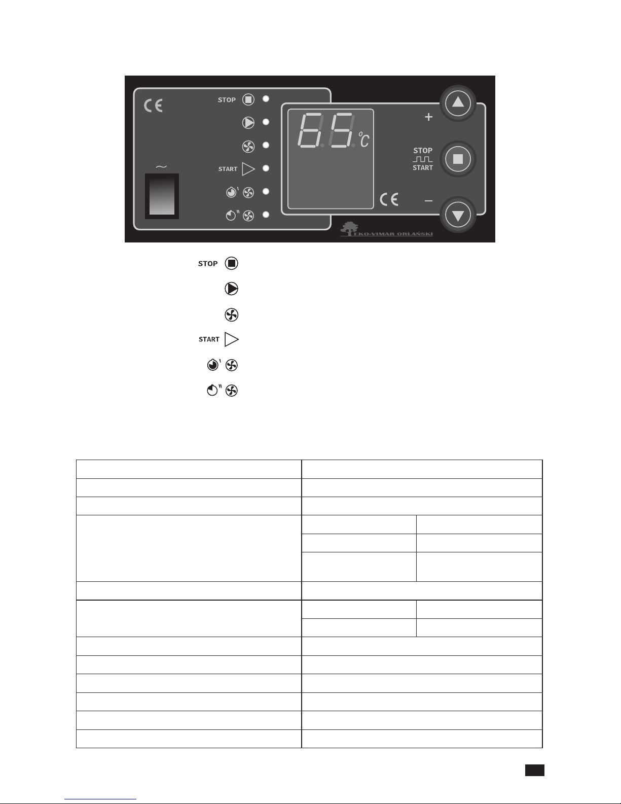
STOP
PUMP’S OPERATION
FAN’S OPERATION
FIRING-UP MODE
BLOW-THROUGH - INTERNAL TIME
FLUSHING - OPERATING TIME
Description of the regulator’s panel
4.5. Technical data of the regulator EKOSTER 2
1. Temperature range -9°C do +99°C
2. Temperature setting +60°C do +80°C
3. Temperature of the pump’s connecting +65°C or controlled with the thermostat
4. Blowdown regulation
seconds 0-90
break 1-15 minutes
possibility of full blushing
turning of
P-0
5. Hysterezis (the difference turn on- turn off) From 2 up to 9°C
6. Maximum switching power
fan 100 W
pump 100 W
7. Mains supply voltage / Frequency 230 V AC, 50 Hz
8. Maximum power consumption 275 VA
9. Fan’s regulating power in % x 10 (regulation range from 20 - 100%)
10. Outside humidity
≤ 95%
11. Protectionrating IP 40
12. Insulation class
I
4.4. Front panel of EKOSTER 2 regulator
8
4.6. The functions of EKOSTER 2
Use
The microprocessor temperature regulator for central heating boiler is designed to control the air
blow in wood-red boiler and to actuate the circulating pump in central heating system
The regulator performs the following functions:
• maintaining the set temperature of boiler by controlling air blow,
• smooths start-up of blower,
• setting the blower power (service mode),
• programmable boiler “blow-through”,
• automatic control switch-off after boiler burnout (extinguishes),
• blower disable when feeding the boiler,
• control of central heating circulating pump depending on its set operating temperature,
• „COMFORT SYSTEM”,
• protection against freezing or overheating of boiler,
• signalling of temperature sensor’s damage,
• regulating the brightness of display - increased during read out and change of regulator settings,
• control panel connecting possibility,
• room thermostat cooperation,
• automatic turning off in case of wrong burning up in the boiler.
Regulator’s working description
After switching on, the regulator passes into state signalled by switching on of corresponding lamp. Operation commences after pressing button or automatically when
boiler’s temperature rises above operating threshold - that is, difference between set boiler
temperature and factory-set temperature difference “dt”. Automatic transition into state
occurs 30 minutes after boiler temperature drops below operating threshold. CONTROL receptacle is for connecting remote control.
Pushbuttons and serve to change the settings. During normal operation, pressing them
causes display and change of set boiler temperature. Pressing and holding pressed causes
increase in speed of temperature setting change.
Pressing the button causes:
• with temperature below operating threshold: switching on or switching off control, signalled
by or indicators respectively,
• with temperature above operating threshold: blower disable signalled by pulsation of
indicator, enabling feeding of fuel into the boiler. Automatic return to operation .
13. Surrounding’s temperature 0 – 40°C
14. Disconnecting type
full
15. Over current protection 2 x 1.25 A (fuse)
NOTICE!
If the “Er” appears on the screen it means that temperature either raised over 99°C, it
decreased below -9°C or the sensor got damaged. To secure together the boiler and
installation up to the time of the sensor replacing pump should be continuously on till
that time.
 Loading...