

Ekosystem AB eurofire XL-GRYM User Manual
Datum 080708, rev 0
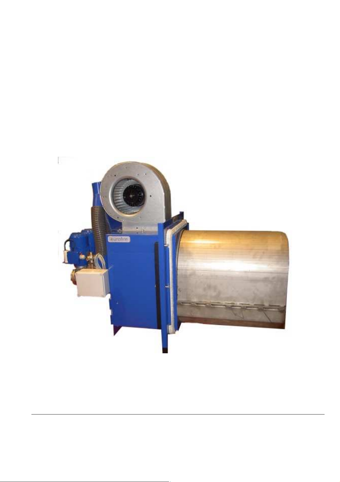
eurofire XL-GRYM
500, 700 kW
The Pellet Burner of the 21st Century
Ekosystem AB
Björkevägen 84, S-805 97 GÄVLE, Sweden

Table of Contents
General Information……………………………………………………………………………………………3
Read these instructions thoroughly before installing and starting the burner…………………………3
Guarantee………………………………………………………………………………………………….….3
Delivery Packing List Check…………...………………………………………………..…………………..3
Access and Free Space around the Burner......................................................................................3
Ashes...............................................................................................................................................3
Boiler Room Air Supply ...................................................................................................................3
Pellets ………………………………………………………………………………………………….……3
Installation..........................................................................................................................................4
Pellet storage and Feed Screw........................................................................................................4
Design and internal structure............................................................................................................4
Temperature Gauge PID Regulator (standard) and Lambda Sensor................................................4
Installation Instructions.....................................................................................................................5
Adjustments of the Burner................................................................................................................8
Delivery Settings..............................................................................................................................8
Chimney Draught.............................................................................................................................8
Negativ Pressure in Combustion Chamber ………………………………………………………….…. 8
Photocell .........................................................................................................................................8
Setting the Thermostats...................................................................................................................8
Pellets Priming Measure ..................................................................................................................8
Start and Stopp the Burner...............................................................................................................8
Fuel Quantity and Pellets Travel Time to the Burner …………………………………………………… 9
Adjustment of Air Supply to the Burner ............................................................................................9
Maintenance and Service................................................................................................................10
Cleaning the Burner.......................................................................................................................10
Photocell........................................................................................................................................10
Electric Ignitiers..............................................................................................................................10
Back-burn Protection......................................................................................................................10
Sprinkler.........................................................................................................................................10
The Equipment’s Safety Systems...................................................................................................10
Electrical Connection Diagram………………………………………………………………….…………11
Connecting ....................................................................................................................................11
Technical Data ……………………………………………………………………………………………….12
Drowing/Dimensions ……………………………………………………………………………………….13
Installation Report ...........................................................................................................................14
Dealer, Name and Address............................................................................................................14
Measured and Installed Settings ...................................................................................................14
Integral part of documentation of eurofire BIG burner is TM3007 User Manual - MPU Control Unit
Instruction.
Ekosystem AB reserves the right to make modifications to its equipment at any time
2

General Information
Read these instructions thoroughly before installing and starting the burner
Thank you for placing your trust and confidence in an Ekosystem AB product. We trust your experience of this
product will be one of total satisfaction, before you use this product please note the following:
For safe and fault free function it is of great importance that the burner is installed correctly and the
instructions for its installation and use are followed. If you are unsure about anything regarding installation
or you have any questions about equipment use contact your supplier for further details.
Installation must be performed by trained and experienced personnel. In the event of incorrect or
unauthorised installation the product guarantee offer from Ekosystem AB will be rendered null and void.
The enclosed guarantee certificate must be completed and sent to Ekosystem AB within ten days of
completion of installation. Any necessary electrical work must only be carried out by a qualified electrician.
In the event of any initial difficulties during start-up, please follow the trouble shooting guide in the
instruction manual. If, however, you can not find the problem, please contact your local eurofire retailer.
We recommend that customers inform their local chimney-sweep of any change of use of their chimney. It
is the user’s responsibility to ensure any local authority regulations are followed when using pellets firing
equipment.
Guarantee
Ekosystem AB offers a one-year guarantee against all manufacturing defects for the eurofire pellet burner and its
components. Items not covered by this guarantee are: the ignition element, damage caused by insufficient
maintenance, faulty handling or incorrect installation. This guarantee does not cover direct or indirect injuries to
third parties or damage to property.
Cost of labour for replacement of components is not included in the guarantee. Ekosystem AB will exchange new
components for defective components if returned to Ekosystem AB within 14 days of installation.
Ekosystem does not receive components sent by freight where the receiver must pay freight charges.
Delivery - Packing List check
Check the packing list and ensure there is no visible damage to the contents. Any damages must be notified
directly to the carrier. The carrier is insured for the transport of the burner. Ensure all listed parts are included in the
delivery and that they are undamaged.
Access and Free Space Around Burner
Building regulations and local bye-laws must be followed.
Ensure there is at least 0.5 metre free access space around the burner to facilitate service and maintenance.
Ashes
Store all ashes in a covered fire-proof container. Ashes can glow for several days! Do not keep combustible
materials in the vicinity of the boiler and burner. Keep boiler room clean and tidy to prevent fire risk.
Boiler Room Air Supply
Ensure the air-intake volume to the boiler room is equal to the chimney draught volume to the out-side air and it is
open. Pellet-heating when in operation requires more air supply than oil-heating operation.
Pellets
Pellets should be of good quality, free from sawdust and hard in consistency. The pellets must be manufactured
from clean and chemical free wood and should weigh between 650 – 700 kgs per cubic meter. The energy content
should be between 4.7 – 5.1 kWh/kg and the ash content should be no higher than 1%. Your pellets dealer will give
you details. Store the pellets in a dry place in able to retain their hard consistency. Pellets damaged by damp and
moisture will be soft and spongy. If these damaged pellets are used it could cause operational difficulties with the
burner equipment.
3

Installation
Pellet Store and Feed Screw
A feed-screw supplies the burner with fuel from an external fuel storage area. The storage area can vary in size,
containing a weeks supply of pellets to a whole years supply.
The pellet store should be so constructed that the feed-screw is at a maximum angle of 45° to the hori zontal floor
plane. The storage area must be enclosed and weather proof in order to protect the pellets from damp and to
shield the rotating feed-screw from unwanted debris.
When constructing large pellet storage areas for bulk pellet supply, your supplier can assist with design and
suggest building materials to achieve best results.
Replenishing pellet to larger storage areas is carried out by pneumatic bulk tankers or in the case of smaller
storage requirements manually from variously sized bags, holding enough for one week or more.
When first starting the burner or if having run out of pellets fuel and the feed-screw is empty; the length of the feedscrew between the storage area and the burner must be filled with pellet before starting the burner. This is
done by covering the feed-screw inlet, at the entrance to the feed-screw, with pellets and then turning on the
power to the feed-screw motor. Allow the feed-screw to remain in operation (10-15 min) until its whole length is
filled with pellets.
Make it a practice to check the quantity of pellets in the feed-screw inlet after each delivery. This is will ensure a
problem free fuel supply, from the storage area, to the burner. WARNING. Do not put fingers or other items in or
near the inlet of the rotating feed-screw!
Store the pellets in a dry place to maintain the pellets original hard consistency. Damp pellets will be soft and shed
particles of saw-dust.
Do not use damp pellets as this may cause operational problems with the equipment.
Install the screw-engine on top of the feed screw and pull it firm. After that, place the feed screw in the intended
pellet store. Make sure it does not slope any steeper than 45°. Fill up with pellets enough to cover the feed screw
inlet properly. Connect the screw to a power point and run it until it is completely filled with pellets.
Design and internal structure
The burner consists of the open Burner Housing.
The Burner Housing and Combustion Area are wholly fabricated in heat-resistant stainless steel.
The twin electrical igniters are positioned and fixed inside the Back-plate.
The Burner Housing and Back-plate contain the primary air supply fan, located down-side the burner and the
secondary air supply fan, located up-side the burner.
There is the photocell unit and a circuitry box with connecting terminals.
The Combustion Area comprises of:
The Cassette with an upper section formed as a hood.
The Casette serves as a retainer for the double electric igniters.
The Burner has two internal Screwfeeders with Motors, which feeds the pellets into Combustion Area.
The Burner also includes a separate MPU Microprocessor Unit and a Feed-Screw for transporting pellets from the
storage area to the burner fall-tube.
(Pellets are delivered from the feed-screw outlet through the fall tube spliter and two fall-tubes to the two internal
screwfeeders and onto the combustion area)
Safeguard security equipment includes:
Photocell and back-burn protection and the Water Safety Thermostat with sprinkler. This sprinkler starts to
extinguish the fire, when the temperature is over 950C.
To protect against fuel back-burn a heat detector is positioned alongside the fall-tube. If the heat detector has been
triggered it must be reset manually for the burner to function.
Temperature Gauge PID Regulator (standard) and Lambda Sensor.
The burner is delivered with a temperature gauge PID regulator, it regulates the wanted running temperature of the
burner and a lambda sond, which controll exhaust gas parameters.
The regulator with cooperation with lambda sensor measures and controls adjustments for achieving and holding
on required temperature by activating full modulational oparation of burner, this reduces the number of start ups
and saves fuel. The regulator’s gauge displays the current boiler temperature in the display-panel of the boiler’s
MPU Controll Unit.
4

Installation Instructions
1. Automatic Feed-Screw
Connect the automatic feed-screw motor to the top of the feed-screw and tighten firmly Place the feed-screw into
the pellets storage bin. Make sure the feed-screw mechanism is not steeper than at a 45° angle to the horizontal
floor plane. Note: when first used, the whole feed-screw must be filled with pellets. Fill the feed-screw inlet with
pellets, enough to cover the feed-screw inlet completely. Connect the motor to prompt clamps into motor electric
box and MPU Controler Box and run until filled with pellets about 15 minutes.
2. Mounting the Burner to The Boiler
Use a plumbers heat-tolerant sealing paste, that has a minimum 250°C tolerance, between construction o f burner
and boiler. The original boiler entrance must be some milimmeters bigger than external dimension of burner
cassette.
4. Chimney draught
is too large to allow 15-30 Pa, a draught stabilizer can be installed to decrease the flue area. If draught pressure is
to small, using chimney fan can be properly.
of 15- 30 Pa is sufficient to run the burner at optimum. If the internal area of the chimney
5. Fix the MPU
and the cable are not exposed to radiant heat from the burner. Ensure the MPU control unit is securely fixed.
Connect cables from the MPU control unit to the burner via the clamps panel attached to the terminal.
Note: Ensure earth cable is also connected!
6. Connect the MPU
(see wiring diagram).
If the boiler has a mains supply previously used for an oil firing system, then this can be used for the pellet burner.
Microprocessor Control Unit onto boiler room wall, pellet store or boiler. Make sure that the unit
unit’s mains cable to a 230 volt supply, draw it through heat-shielding and into the boiler
7. Place the burners
together with other cables, then temperature parameters can be affected.
immersion temperature gauge into the boiler. Note: If this cable is drawn through
5
 Loading...