


COMPRESSOR
KOMPRESSOR
COMPRESSORE
DK50 2V/M MOBILE
MANUFACTURER
HERSTELLER
PRODUTTORE
EKOM spol. s r. o.
Priemyselná 5031/18
SK-921 01 Piešťany
Slovak Republic
tel.: +421 33 7967255
fax: +421 33 7967223
www.ekom.sk
email: ekom@ekom.sk
DATE OF LAST REVISION
DATUM DER LETZTEN ÜBERARBEITUNG
DATA DELL'ULTIMA REVISIONE
07/2015

07/2015 - 3 - NP-DK50 Plus, DK50 2V -MOBILE-MD-16_07-2015
CONTENTS................................. 2
INHALT....................................... 16
CONTENUTO.............................. 28
JULY 2015
Z-1238/2015
Pgs. 31 - pos.3,31

INSTRUCTIONS FOR USE
NP-DK50 Plus, DK50 2V -MOBILE-MD-16_07-2015 - 2 - 07/2015
CONTENTS
INSTRUCTIONS FOR USE ..................................................................................................................... 3
IMPORTANT INFORMATION ............................................................................................................. 3
1. CE MARKING ............................................................................................................................ 3
2. WARNINGS ................................................................................................................................ 3
3. ALERT NOTICES AND SYMBOLS ............................................................................................ 4
4. STORAGE AND TRANSPORT .................................................................................................. 4
5. TECHNICAL DATA ..................................................................................................................... 5
6. PRODUCT DESCRIPTION ........................................................................................................ 6
7. FUNCTION ................................................................................................................................. 6
INSTALLATION ................................................................................................................................... 9
8. USE ............................................................................................................................................. 9
9. INSTALLATION .......................................................................................................................... 9
10. FIRST OPERATION ................................................................................................................. 11
OPERATION ..................................................................................................................................... 11
11. SWITCHING THE COMPRESSOR ON ................................................................................... 11
MAINTENANCE ................................................................................................................................ 12
12. MAINTENANCE SCHEDULE ................................................................................................. 12
13. MAINTENANCE ........................................................................................................................ 12
14. STORAGE ................................................................................................................................ 14
15. DISPOSING OF THE APPLIANCE .......................................................................................... 14
16. REPAIR SERVICE .................................................................................................................... 14
17. SOLVING PROBLEMS ............................................................................................................. 14
SERVICE MANUAL ............................................................................................................................ 41
18. WIRING DIAGRAMS ............................................................................................................. 41
19. SPARE PARTS ....................................................................................................................... 44
PARTS LIST ........................................................................................................................................ 60

INSTRUCTIONS FOR USE
07/2015 - 3 - NP-DK50 Plus, DK50 2V -MOBILE-MD-16_07-2015
INSTRUCTIONS FOR USE
IMPORTANT INFORMATION
1. CE MARKING
Products labeled with compliance mark CE meet safety Guidelines of the European Union. (98/37/EEC Council Directive of Safety of Machinery, 73/23/EEC – Low-voltage directive), EMC.
2. WARNINGS
2.1. General warnings
This Installation, Operation and Maintenance Manual is a part of the appliance and must be kept with the
compressor. Careful review of this manual will provide the information necessary for correct operation of
the appliance.
The safety of operating personnel and trouble-free operation of the appliance are guaranteed only if
original parts are used. Only accessories and parts mentioned in the technical documentation or expressly
approved by the manufacturer can be used.
If any other accessories or consumable materials are used, the manufacturer cannot be held responsible
for the safe operation of the appliance. This guarantee does not cover damages originating from the use
of accessories or consumable material other than those specified or suggested by the manufacturer.
The manufacturer guarantees the safety, reliability and function of the appliance only if:
- Installation, new settings, amendments, extensions and repairs are performed by the manufacturer or
its representative, or a service provider authorized by the manufacturer
- The appliance is used in accordance with this Installation, Operation and Maintenance Manual
The manufacturer reserves all rights for the protection of its wiring diagrams, methods and names.
Translation of Manual for Installation, Operation and Maintenance is carried out in accordance with the
best knowledge. In the case of ambiguities, the Slovak version of the text prevails.
2.2. General safety warnings
The manufacturer developed and designed the equipment in such a way so that any risks were excluded if it
is used according to intention. The manufacturer considers it to be its obligation to describe the following
safety measures in order to exclude residual damages.
Operation of the appliance must be in compliance with all local codes and regulations.
Original packaging should be kept for the return of the appliance. Only the original packaging ensures
protection of the appliance during transport. If it is necessary to return the appliance during the guarantee
period, the manufacturer is not liable for damages caused by improper packaging.
Each time the appliance is used, the operator must make sure that it is functioning correctly and safely.
The user must fully understand the operation of the appliance.
The product is not intended for operation in areas with a risk of explosion.
2.3. Electrical system safety warnings
The appliance must be connected to earth (grounded).
Before the appliance is plugged in, make sure that the mains voltage and mains frequency stated on the
appliance are the same as the power mains.
Prior to putting into operation it is necessary to check for possible damage of the equipment and
connected air and electric distributions. Damaged pneumatic and electric lines must be immediately
replaced.
Immediately disconnect the appliance from the elektric mains if a technical failure occurs.
During repairs and maintenance, ensure that:
- The appliance is disconnected from the mains
- Pressure pipes are vented and pressure is released from the air tank.
The appliance must be installed by an approved, qualified technician.
INSTRUCTIONS FOR USE
NP-DK50 Plus, DK50 2V -MOBILE-MD-16_07-2015 - 4 - 07/2015
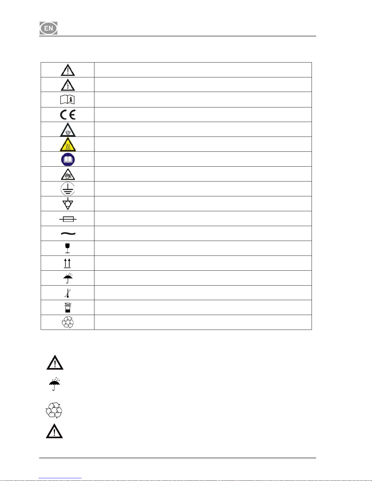
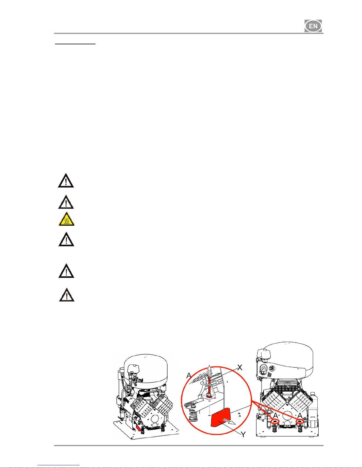
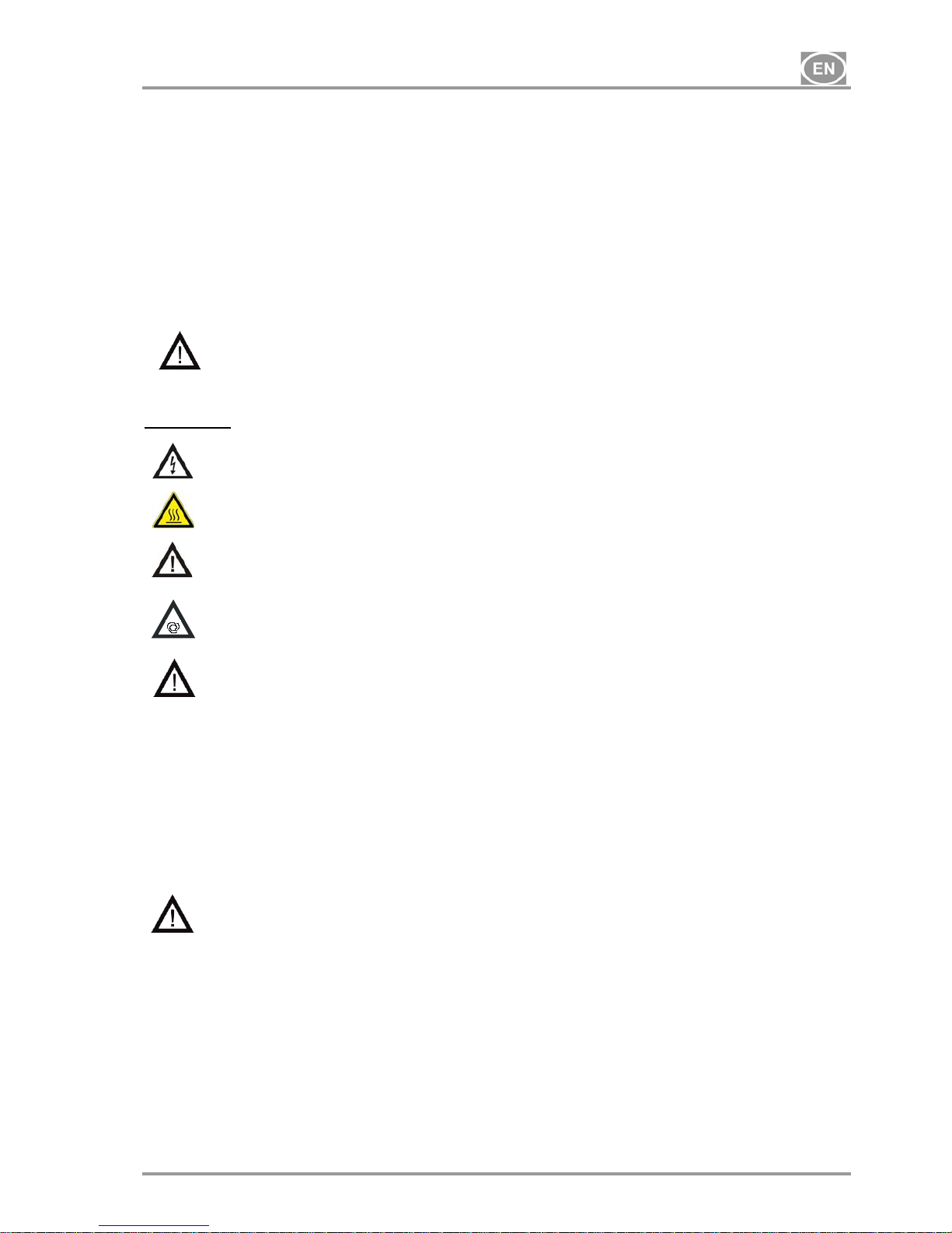
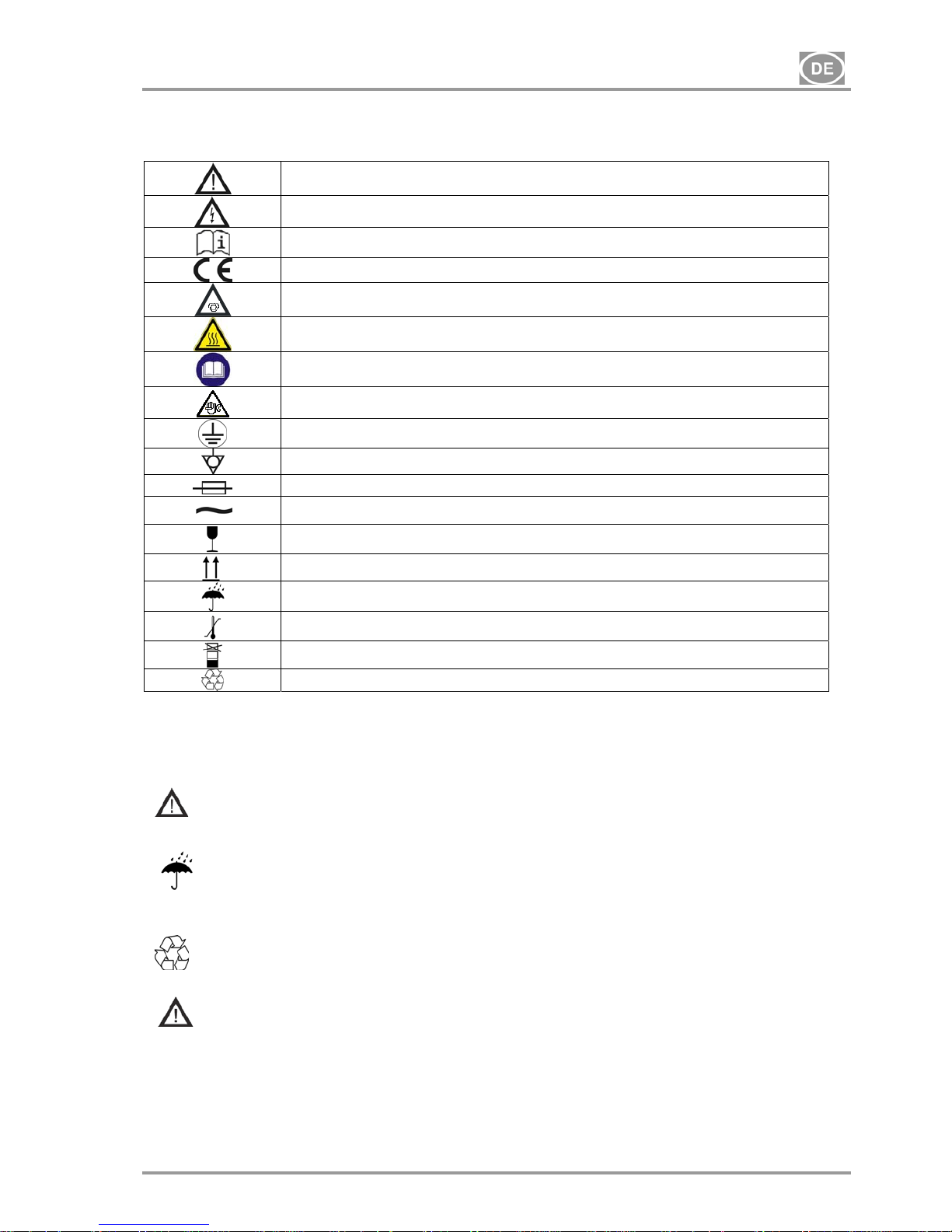
3. ALERT NOTICES AND SYMBOLS
In the Installation, Operation and Maintenance Manual and on packaging and product, the following labels or
symbols are used for important information:
Information, instructions and cautions for the prevention of damage to health or
materials
Caution, risk of electric shock
Consult instructions for use
CE mark of compliance
Compressor is remote-controlled and may start without warning
Caution! Hot surface
Instruction : read the user manual.
Caution : Performed maintenance works
Earth (ground) connection
Terminal for ground connection
Fuse
Alternating current
Handling mark on package – FRAGILE
Handling mark on package – THIS SIDE UP
Handling mark on package – KEEP DRY
Handling mark on package – TEMPERATURE LIMITATIONS
Handling mark on package – LIMITED STACKING
Mark on package – RECYCLABLE MATERIAL
4. STORAGE AND TRANSPORT
The compressor is shipped in cardboard that protects the appliance from damage during transport.
Caution! For transport, always use the original packaging and secure the compressor in
the upright position.
Protect the compressor from humidity and extreme temperatures during transport and storage. A
compressor in its original packaging can be stored in a warm, dry and dust-free area. Do not
store near any chemical substances.
Keep packaging material if possible. If not, please dispose of the packaging material in an
environmentally friendly way and recycle if possible.
Caution! Before moving or transporting the compressor, release all the air pressure from
the tank and hoses and drain the condensed water.
INSTRUCTIONS FOR USE
07/2015 - 5 - NP-DK50 Plus, DK50 2V -MOBILE-MD-16_07-2015
Climatic conditions during storage and transport
Temperature : –25°C to +55°C, 24 h to +70°C
Relative air humidity : 10% to 90 % (no condensation)
Climatic operation conditions
Temperature : +5°C to +40°C
Relative air humidity : 70%
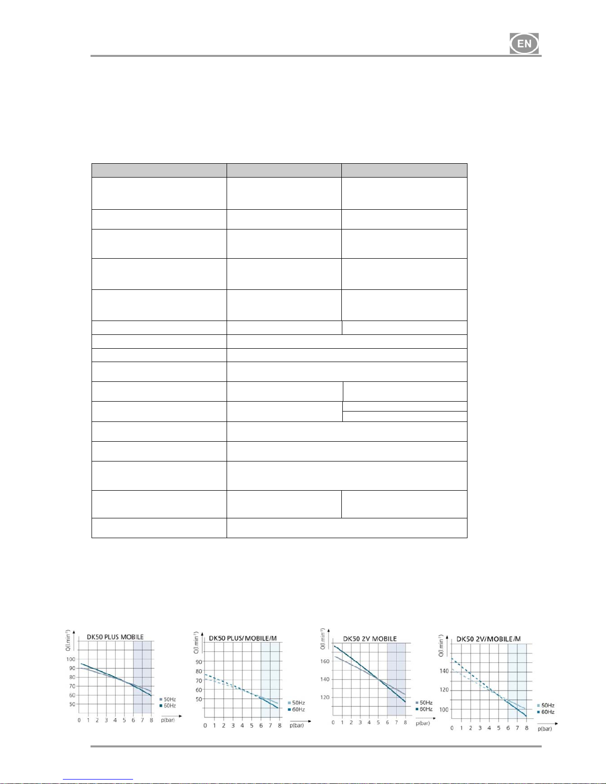
5. TECHNICAL DATA
DK50 PLUS MOBILE DK50 2V MOBILE
Nominal voltage / (*)
frequency
V / Hz
230 / 50
230 / 60
115 / 60
230 / 50
230 / 60
115 / 60
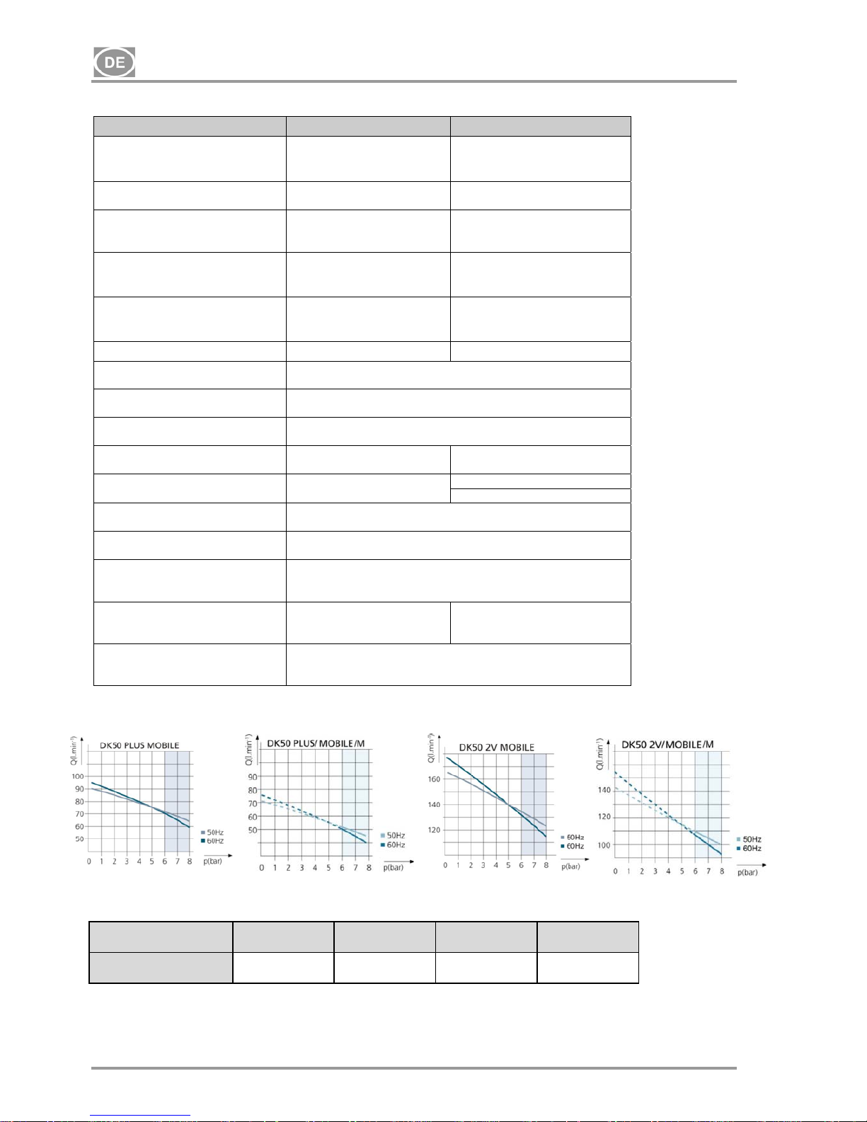
Efficiency of compressor at overpressure 6 bar Lit.min
-1
72 (50Hz)
70 (60Hz)
134 (50Hz)
132 (60Hz)
Efficiency of compressor with
dryer at over-pressure 6 bar
Lit.min
-1
60 (50Hz)
55 (60Hz)
105 (50Hz)
100 (60Hz)
Maximal current
A
3,5
4,4
8,8
7,8
8,8
16,4
Maximal current of compressor
with dryer
A
3,7
4,6
9
8,1
9,1
16,6
Motor performance kW
0,55 1,1
Air tank capacity Lit.
25
Pressure range bar
6,0 – 8,0
Maximum operating pressure of
safety valve bar
12,0
Sound level L
pfA
[dB] 57 (50Hz)
59 (60Hz)
62 (50Hz)
64 (60Hz)
Mode of operation of compressor
Continual S 1
Continual S 1
Intermittent S 3-60% (**)
Mode of operation of compressor
with dryer
Continual S 1
Dimensions of compressor
w x l x h mm
580x700x1010
Dimensions of compressor
packaged in cardboard
w x l x h mm
740x860x1200
Weight of compressor /
of compressor with dryer kg
100 / 105 104 / 110
Drying point of compressor
Atmospheric condensation point
-20°C
(*) When ordering, please specify the version of the compressor
(**) Applicable for voltage version of
115/60
- Air outgoing from membrane dryer M is filtered using 0,3µm filter
INSTRUCTIONS FOR USE
NP-DK50 Plus, DK50 2V -MOBILE-MD-16_07-2015 - 6 - 07/2015
5.1. FAD efficiency correction for differences in elevation
FADcorrectiontable
FAD efficiency refers to conditions at an elevation of 0 mamsl: Temperature: 20°C
Atmospheric pressure: 101325 Pa
Relative humidity: 0%
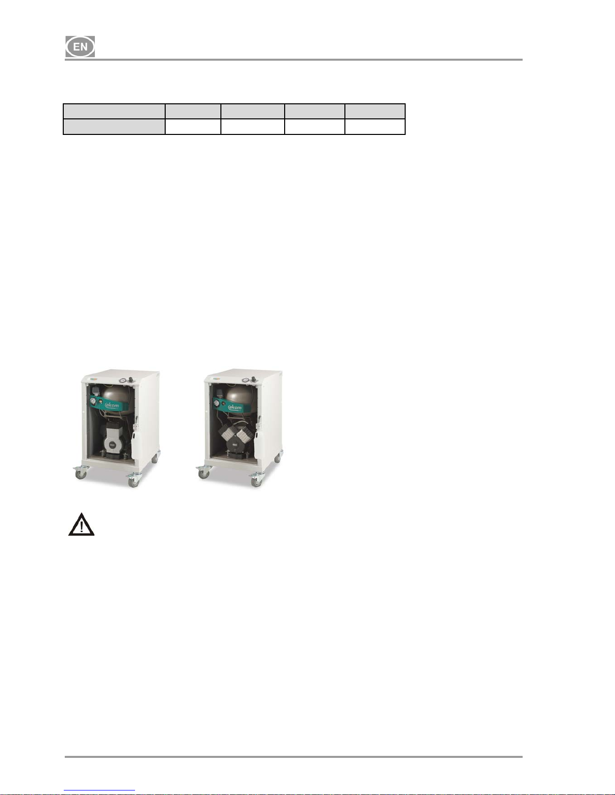
6. PRODUCT DESCRIPTION
6.1. Model variations and their uses
Compressors are the source of clean, oil-free compressed air used to drive appliances and pneumatic
equipment.
Compressors models are designed for the following uses:
Compressors DK50 PLUS MOBILE
DK50 2V MOBILE
- are placed in soundproof boxes.
Compressors DK50 PLUS/M MOBILE
DK50 2V/M MOBILE
- are placed in soundproof boxes and feature an membrane air dryer.
DK50 PLUS MOBILE DK50 2V MOBILE
The compressed air from a compressor is not suitable for the operation of breathing
appliances or similar equipment.
7. FUNCTION
Compressor (Fig.1 )
The compressor (1) draws in air through a filter (8) and compresses it through a check valve (3) into an air
tank (2). The connected apparatus draws the compressed air from the air tank until the pressure drops to a
default preset level on the air-pressure switch (4) switching the compressor on. The compressor again
compresses air into the nozzle until the maximum pressure is reached and the compressor switches off.
After compressor aggregate is switched off, pressure hose shall be pressure-release solenoid valve (6).
Safety valve (5) prevents the pressure in air chamber from rising above the maximal allowed value. The
automatic drain of the condensate (Autodrain) (15) releases the condensate from the air nozzle.
Compressed, clean air free from oil traces is stored in the air tank ready for use.
Compressor with dryer (Fig.2)
The compressor unit (1) pulls in outside air through the inlet filter (8) and compresses it through the cooler
(14), filter (13) and micro-filter (12) to the dryer (9) and on through the check valve (3) as dry clean air in the
air tank (2). Condensate from the filter and micro-filter is automatically drained into the collection vessel. The
dryer provides continuous drying of the compressed air.
Box of the compressor (Pic. No. 3)
Box is designed with casters (2 – braked and 2- without brake) in a way that internal shape of the box
ensures proper position of the compressor. Increased stiffness of the box constructions and used durable
Elevation[mamsl] 0‐1500 1501‐2500 2501‐3500 3501‐4500
FAD[l/min] FADx1 FADx0.8 FADx0.71 FADx0.60

INSTRUCTIONS FOR USE
07/2015 - 7 - NP-DK50 Plus, DK50 2V -MOBILE-MD-16_07-2015
17
casters ensure easy and simple handling. Box consists of base construction (with casters) and lid joint with
4 posts. There is also cover consisting of 4 boards (doors). Each board (doors) can be removed after are 2
no delay screws unscrewed.
There are manometer of output pressure, pressure control, power switch, visual signaling ON/OFF (green
light), signaling of decreased temperature of the box (orange light), hour meter in the front part of the upper
lid of the box. Box is electrically connected with compressor trough the electric cord in the socket (32).
Electric socket is in the down back part of the box (24). Pneumatic connection is made by hose Ø 6/4 for
draining of the condensate from drier with bush of the condensate output from the box (25) and output of the
pressurized air from the compressor (34) is made by hose Ø 10/8 (35) into press control (40) of the box.
Output of the pressurized air with internal thread G1/4 is placed on the top of the box (26). For draining the
condensate is on the whichever side of the chosen post made hose bush. Draining of the condensate from
the box is possible to do through these bushes in the posts of the box. (26). After switching on the power
switch (36) of the box, equipment works in automatic mode.
In the back part of the box are cooling fans (38), blowing the hot air out of the box through vents for hot air
output (27). Cooling fans are activated by thermal switch when is reached temperature 40 °C. Fans works
until the temperature of the box decreases on the value 32 °C. Mode of increased temperature (above 80 °C)
in the box – COOLING ERROR – is signalized by orange light in the board (39). It is activated by thermal
switch.
Make sure that nothing impedes the free flow of air under and around the compressor.
Never cover the hot air outlet on the top back side of the case.
Fig.1 – Compressor
Fig. 2 - Compressor with membrane air dryer
1. Compressor motor
2. Air tank
3. Check valve
4. Pressure switch
5. Safety valve
6. Solenoid valve
7. Fan of compressor
8. Input filter
9. Dryer chamber
10. Silencer
11. Bottle
12. Mikrofilter
13. Filter
14. Cooler
15. Autodrain
16.
Vessel cap
17.
Check valve
17
INSTRUCTIONS FOR USE
NP-DK50 Plus, DK50 2V -MOBILE-MD-16_07-2015 - 8 - 07/2015
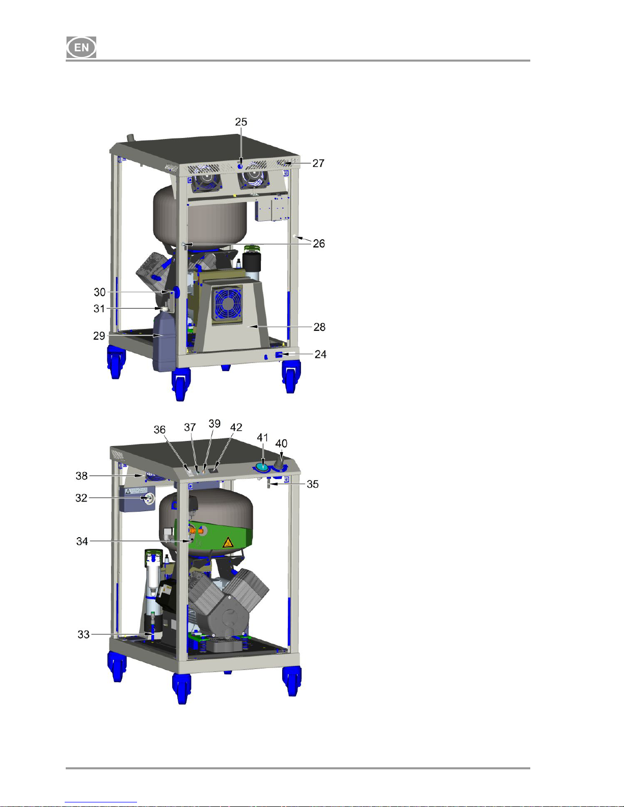
Fig.3 - Box
A- Cabinet (without panels) – rear
view
24. Socket
25. Air pressure output (internal thread
G 1/4“)
26. Variant holes for condensate outlet
from housing for hose with Ø 6/4
27. Heated air output holes
28. Tunnel of ventilator for dryer
29. Bottle for condensate collection
30. Magnetic vessel holder
31. Vessel cap
B- Housing (without panels) with
compressor DK50 2V/M
32. El. socket for compressor
33. Output from a filters for condensate
outlet via hose with Ø 6/4
34. Output of compressed air from
compressor via hose with Ø 10/8
35. Place for input of hose with Ø 10/8
into pressure regulator from output of
compressed air from compressor
36. Mains switch
37. Green indicator of mains switch
turning on
38. Ventilators
39. Orange indicator of operation mode
at raised temperature
40. Pressure regulator
41. Manometer
42. Hour meter
INSTRUCTIONS FOR USE
07/2015 - 9 - NP-DK50 Plus, DK50 2V -MOBILE-MD-16_07-2015
Unpacking Fig.4
INSTALLATION
8. USE
The appliance must be installed and operated in a dry, well ventilated and dust-free area where ambient
temperature is within the range of +5°C to +40°C and relative air humidity does not exceed 70%.
Otherwise, failure-free operation of the compressor cannot be guaranteed. The compressor must be
installed so that it is accessible at all times for operation and maintenance. Please ensure that the
appliance label is accessible.
The appliance must stand on a flat, sufficiently stable base. See paragraph 5 (Technical data) when
positioning or lifting the compressor.
Compressors cannot be exposed to outdoor environments. The appliance cannot be used in moist or wet
environments. Do not use the compressor in the presence of explosive gases, dust or combustible liquids.
Prior to connecting the compressor to the device the supplier must assess whether the medium – air
available meets the requirements of the particular purpose of application. Therefore respect the
specification of the product. Classification and assessment of compliance should be carried out by the
supplier of the end product.
Any use other than that described in this manual is not covered by the guarantee, and the manufacturer is
not liable for any damages that may result. The operator/user assumes all risk.
9. INSTALLATION
Only qualified personnel can install and start up the appliance and train operating
personnel in its correct use and maintenance. Installation and training of all operators
shall be confirmed by the installer’s signature on the certificate of installation.
Prior to installation, ensure that the compressor is free of all transport packaging and
stabilizers to avoid any risk of damage to the product.
Caution! When in operation, the compressor is hot. Burns or fire may result if contact is
made by the operator or any flammable material.
Lead for the connection for electric mains and air hose must not be broken.
Mobile supply of electric energy must not be exposed to pulling, it must be free (it is
forbidden to put any objects on it), t is forbidden to load it thermally in any way.
Compressor put into the case may be operated only in the rooms with permanently good
circulation of air, sufficiently distant from the sources of heat, or direct impact of sun
radiation.
The appliance must be located minimally 100 mm from the wall for enabling blowing of
cooling air. Non-observance of the given distance may be the cause of damage to the
compressor and case!
9.1. Placement of the compressor
INSTRUCTIONS FOR USE
NP-DK50 Plus, DK50 2V -MOBILE-MD-16_07-2015 - 10 - 07/2015
Compressor (Fig.3 and 4 )
Unpack compressor, unscrew front board (after unscrewing 2 no delay screws) and disconnect earthing wire.
Remove fixing parts X and Y (Detail A). The compressor shall be fixedly connected with the housing using
screws that must not be disassembled (4 pcs). Connect the appliance to outlet of compressed air from the
housing. Connect the power cord plug leading from the housing into the mains socket.
After placing the panel it is necessary to connect grounding wire leading from the housing lid and
only afterwards to close it and fix using screws!
To drain the condensate from the box is possible through bushes in the posts. It is possible to chose any
position of the bushing (26) on the post – it is possible to chose from two positions in case of choice of other
side than from production, it is necessary to dismantle used bushing and replace in in the selected side.
Connect hose PU Ø 6/4 mm with drier or with automatic drain of the condensate (autodrain). Attach the
delivered angular insertion piece and PU hose with Ø 6/4 mm onto the external side of the housing.
Assemble the holder for a vessel for condensate collection. Insert the supplied blowing out noise suppressor
and connect it with the condensate outlet transition piece using hose with Ø 6/4. When fixing the holder with
a vessel at the housing side it is necessary to consider a space of at least 110 mm between the housing and
furniture. Distance smaller than the specified one may cause problem with handling of the vessel.
9.2. Compressed air outlet
(Fig.3)
There is a G1/4“ outlet with internal thread (25) for the connection of pressure hose in the rear upper part of
the housing.
9.3. Electrical connection
Plug the electrical cord into the mains.
The appliance is equipped with a grounded plug. Make sure this connection complies with
local electrical codes. The mains voltage and frequency must comply with the data stated
on the appliance label.
Keep the socket easily accessible to ensure that in an emergency the appliance can be safely
disconnected from the mains.
The relevant current circuit must be protected in the electricity distribution with circuit breaking element.
Electrical cable may not contact the hot parts of a compressor. Insulation could be
damaged!
If any electrical cord or air hose is damaged it must be replaced immediately.
INSTRUCTIONS FOR USE
07/2015 - 11 - NP-DK50 Plus, DK50 2V -MOBILE-MD-16_07-2015
10. FIRST OPERATION
(Fig.3)
Make sure that all stabilizers used during transport were removed.
Check that all pressurized air line connections are secure.
Connect to the mains.
Turn the switch (36) on the soundproof box to the position “I“.
Compressor - At first operation the air tank is pressurized until it reaches a preset level when the
compressor automatically switches off. As the air is used, the compressor works in automatic mode,
switched on or off by the pressure switch.
Compressor with dryer - In addition, adsorption dryer takes out humidity from the previous compressed air
during operation in the device.
The compressor is not equipped with an emergency power supply.
OPERATION
In case of emergency, disconnect the compressor from the mains (pull out the mains
plug).
The compressor has hot surfaces.
Burns or fire may result if contact is made.
During prolonged operation of the compressor, the temperature in the box may increase to
over 40°C. At this point the cooling fan automatically switches on. After cooling the space
to under 32°C, the ventilator switches off.
Automatic start: when pressure in the tank drops to the pressure switch’s lower limit level,
the compressor automatically switches on. The compressor automatically switches off
after reaching the pressure switch’s upper limit level.
Prior to operation it is necessary to connect the housing using output transition piece for
compressed air via internal thread G 1/4“. Disconnect the connected device only after the
reduction of pressure in the pneumatic system to zero!
11. SWITCHING THE COMPRESSOR ON
(Fig. 3)
Switch on the compressor by switch (36) on the soundproof box to the position “I“, the compressor sends
pressurized air to the air tank. As the compressed air is used, the pressure in the air nozzle drops to a
preset level, the compressor switches on and the air nozzle files with compressed air. After reaching the
cutoff pressure the compressor turns off automatically and the cycle is repeated.
Check the value of switching-on and switching-off pressure on pressure gauge (41). The values may be
within a tolerance of 10%. Air pressure in air chamber must not exceed maximal permitted operation
pressure.
Never tamper with the pressure switch. Adjustments are not allowed. The pressure switch
(Fig.1 - Poz.4) has been set by the manufacturer and further setting of switching on and off
pressure may be carried out only by a qualified expert trained by the manufacturer.

INSTRUCTIONS FOR USE
NP-DK50 Plus, DK50 2V -MOBILE-MD-16_07-2015 - 12 - 07/2015
MAINTENANCE
12. MAINTENANCE SCHEDULE
Notice!
The operating entity is obliged to ensure that all tests of the equipment are carried out repeatedly at
least once within every 24 months (EN 62353) or in intervals as specified by the applicable national
legal regulations. A report must be prepared on the results of the tests (e.g.: according to EN 62353,
Annex G), including the measurement methods used.
Maintenance that must be performed Chapte
r
Time interval Performed by
• Empty condensate from the bottle
14.2 1 x day or after filling
operating staff
• Check safety valve
14.3
1 x year qualified
technician
• Replacement of input filter and pre-filter
14.4
1 x every 2 years or after 4000 hours
of operation
qualified
technician
• Replacement of filter element in filter
and micro-filter
14.5
14.6
1 x year operating staff
• Testing of joints tightness and control
inspection of the appliance
2000 hours of operation or after one
year
qualified
technician
• Perform “Repeated Test” according
to EN 62353
13 1 x every 2 years
qualified
technician
13. MAINTENANCE
Repair work beyond normal maintenance can be performed only by qualified personnel or
the manufacturer’s representative.
Use only spareparts and accessories approved by the manufacturer.
Prior to any maintenance or repair work, switch off the compressor and disconnect it from
the mains (pull out the mains plug).
TO ENSURE THAT THE COMPRESSOR WORKS CORRECTLY, PERFORM THE FOLLOWING
MAINTENANCE TASKS AT REGULAR INTERVALS (CHAPTER 13).:
13.1. Cleaning of the Product
Clean the product using common detergent agents or agents on alcohol base. It is not permitted to clean the
product using agents that comprise abrasive component, chemical solvents and the other aggressive
substances.
13.2. Condensation drain valve
Compressors
During regular operation is condensate automatically drained through automatic drain (autodrain) which is
catched into a bottle. Pull the bottle out of the holder and pour out the condensate.
Compressors with air dryer
In the case of a regular operation condensate is automatically excreted via air dryer and it is entrapped in a
bottle. Take out the bottle from a holder, release blowing-out suppressor and pour out the condensate.
Prior to the following checks it is necessary to disassemble the housing door.
INSTRUCTIONS FOR USE
07/2015 - 13 - NP-DK50 Plus, DK50 2V -MOBILE-MD-16_07-2015
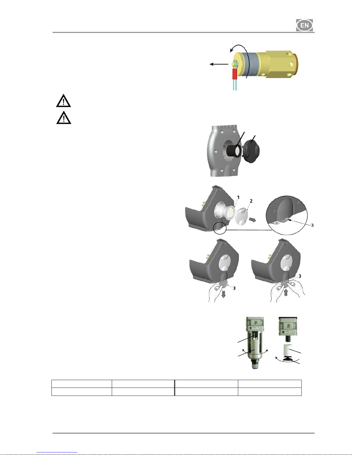
13.3. Safety valve check
(Fig.5)
When the compressor is operated for the first time,
make sure that the safety valve is working properly.
Turn screw of safety valve several rotations to the
left until the safety valve releases air. Let the
safety valve blow out for only a few seconds. Turn
screw to the right until it seats, closing the valve.
The safety valve must never be used for depressurizing the air tank. It could damage the
safety valve. The valve is set to the maximum permitted pressure by the manufacturer.
Adjustments are not permitted.
Warning! Compressed air can be dangerous. Wear eye protection when blowing air out.
13.4. Replacement of the input filter and prefilter
(Fig.6)
At the lid of the compressors crankcase is an
input filter (1) and prefilter (3).
Replacing of the input filter:
Hand pull the rubber stopper (2).
Remove used and dirty filter.
Input new filter and set rubber stopper.
Replacing of the prefilter:
Hand pull prefilter (3).
Replace old prefilter with new.
13.5. Replacement of filter element in filter
(Fig.7)
Loosen a safety-catch (1) on a filter regulator by pulling it down.
Turn the container slightly (2) and pull out.
Unbolt the filter holder (3).
Change the filter bed (4), bolt the filter holder.
Put the filter container on and secure it by turning it until the safety-
catch is fixed.
Filter Order number Filter insert Order number
AF 30-F02C 025200005
AF 30P-060S 5 m
025200061
Fig.5
2V
Fig.6
PLUS
1
2
4
3
Fig.7
INSTRUCTIONS FOR USE
NP-DK50 Plus, DK50 2V -MOBILE-MD-16_07-2015 - 14 - 07/2015
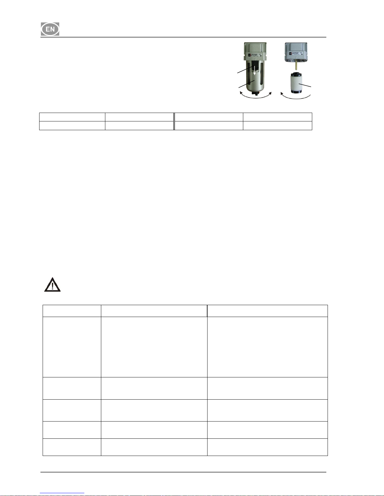
13.6. Replacement of filter element in mikrofilter
(Fig.8)
Loosen a safety-catch (1) on a micro filter by pulling it down.
Turn the container slightly (2) and pull out.
Unbolt the filter (3).
Change and bolt the filter bed.
Put the filter container on and secure it by turning it until the safetycatch is fixed.
14. STORAGE
When there is a predisposition that the compressor shall not be used for a prolonged time period, release air
pressure in the pressure tank. Switch off the compressor by switch (36) (Fig.3) and disconnect the appliance
from the mains.
15. DISPOSING OF THE APPLIANCE
• Disconnect the appliance from the mains.
• Release air pressure in the pressure tank.
• The components of the product are non-toxic.
• Dispose of the appliance following all environmental regulations.
16. REPAIR SERVICE
Guaranteed and post-guarantee repairs must be done by the manufacturer, its authorized representative, or
service personnel approved by the supplier.
The manufacturer reserves the right to make changes to the appliance without notice. Any changes made
will not affect the functional properties of the appliance.
17. SOLVING PROBLEMS
Caution! Before proceeding, depressurize the air tank to zero and disconnect the
appliance from the mains.
Troubleshooting can be performed only by qualified personnel.
FAILURE POSSIBLE CAUSE REMEDY
Compressor does not start No voltage in pressure switch Check voltage in socket
Check fuse – replace faulty one
Loosen terminal – tighten it
Check power cord – replace faulty one
Disconnected winding of motor, damaged thermal
protection
Faulty capacitor
Seizure of piston or another rotary part Pressure
switch does not switch on
Mains cord from compressor is not connected to
socket of the case.
Replace motor or re-wind it
Replace capacitor
Replace damaged parts
Check the function of pressure switch
Connect mains plug from compressor to socket in the
case (32) (Fig.3)
Compressor often
switches on
Air leak in pneumatic distribution system
Leaking check valve
Greater volume of condensed liquid in pressure
vessel
Check pneumatic distribution system – seal loose joint
Clean valve, replace seals, replace valve
Drain condensed liquid
(autodrain out of function)
Prolonged running of
compressor
Air leak in pneumatic distribution system
Worn piston ring
Contaminated filter
Defective solenoid valve
Check pneumatic distribution system – seal loose joint
Replace worn piston ring
Replace contaminated filter with the new one
Repair or change the valve
Compressor is noisy
(knocking, metal noises)
Damaged bearing of piston, piston rod, motor
bearing
Loose or cracked spring
Replace damaged bearing
Replace damaged spring
Dryer doesn´t dry
(condensed water in the
tank)
Contaminated filter or microfilter
Replace contaminated filter with the new one
Mikrofilter Order number Filter insert Order number
AFM 30-F02C 025200007
AFM 30P-060AS 0,3 m
025200076
Fig.8
2
3
1

GEBRAUCHSANWEISUNG
07/2015 - 15 - NP-DK50 Plus, DK50 2V -MOBILE-MD-16_07-2015
INHALT
GEBRAUCHSANWEISUNG ................................................................................................................. 16
WICHTIGE INFORMATIONEN ......................................................................................................... 16
1. CE KENNZEICHNUNG ............................................................................................................ 16
2. HINWEISE ................................................................................................................................ 16
3. WARNHINWEISE UND SYMBOLE ......................................................................................... 17
4. LAGER- UND TRANSPORTBEDINGUNGEN ......................................................................... 17
5. TECHNISCHE DATEN ............................................................................................................. 18
6. PRODUKTBESCHREIBUNG ................................................................................................... 19
7. FUNKTIONSBESCHREIBUNG ................................................................................................ 19
INSTALLATION ................................................................................................................................. 22
8. NUTZUNGSBEDINGUNGEN ................................................................................................... 22
9. PRODUKTINSTALLATION ...................................................................................................... 22
10. ERSTE INBETRIEBNAHME .................................................................................................... 24
BEDIENUNG ..................................................................................................................................... 24
11. EINSCHALTEN DES KOMPRESSORS ................................................................................... 24
WARTUNG ........................................................................................................................................ 25
12. WARTUNGSINTERVALLE ...................................................................................................... 25
13. WARTUNG ............................................................................................................................... 25
14. LAGERUNG ............................................................................................................................. 27
15. ENTSORGUNG DES GERÄTES ............................................................................................. 27
16. INFORMATIONEN ÜBER REPARATURBETRIEBE ............................................................... 27
17. FEHLERSUCHE UND FEHLERBEHEBUNG .......................................................................... 27
SERVICEHANDBUCH .......................................................................................................................... 41
18. SCHALTPLAN .......................................................................................................................... 41
19. VERZEICHNIS DER ERSATZTEILE ....................................................................................... 44
LIEFERUMFANG .................................................................................................................................. 60

GEBRAUCHSANWEISUNG
NP-DK50 Plus, DK50 2V -MOBILE-MD-16_07-2015 - 16 - 07/2015
GEBRAUCHSANWEISUNG
WICHTIGE INFORMATIONEN
1. CE KENNZEICHNUNG
Die Produkte mit der CE Kennzeichnung erfüllen die Sicherheitsrichtlinien (98/37/EEC - Council Directive of
Safety of Machinery, 73/23/EEC – Low-voltage directive) der Europäischen Union, EMC.
2. HINWEISE
2.1. Allgemeine Hinweise
Die Anleitung zur Installation, Bedienung und Wartung ist Bestandteil des Gerätes. Es ist notwendig, dass
sie in der Nähe des Aufstellungsortes des Gerätes immer zur Verfügung steht. Genaues Befolgen dieser
Anleitung ist eine Voraussetzung für ordnungsgemäße Nutzung des Gerätes und eine korrekte Bedienung.
Die Sicherheit des Bedienungspersonals und fehlerfreier Betrieb des Gerätes sind nur bei der Nutzung von
Originalgeräteteilen garantiert. Es dürfen nur Zubehör- und Ersatzteile genutzt werden, die in der
technischen Dokumentation aufgeführt oder ausdrücklich vom Hersteller erlaubt sind. Wird anderes
Zubehör genutzt, so kann der Hersteller keine Garantie für sicheren Betrieb und sichere Funktion
übernehmen.
Schäden, die durch Nutzen von anderem als vom Hersteller vorgeschriebenem Zubehör entstehen, sind
von der Gerätegarantie ausgeschlossen.
Der Hersteller übernimmt die Verantwortung für die Sicherheit, Zuverlässigkeit und Funktion des Gerätes
nur dann, wenn:
- Installation, Einstellungen, Veränderungen, Erweiterungen und Reparaturen vom Hersteller oder
vom Hersteller beauftragten Organisationen durchgeführt werden.
- die Nutzung des Gerätes in Übereinstimmung mit der Anleitung für Installation, Bedienung und
Wartung erfolgt.
Die Anleitung entspricht zum Zeitpunkt des Druckes der Ausführung des Gerätes und den zugehörigen
sicherheitstechnischen Vorschriften. Der Hersteller behält sich alle Rechte zum Schutz der aufgeführten
Schaltungen, Methoden und Bezeichnungen vor.
Die Übersetzung der Anleitung zur Installation, Bedienung und Wartung erfolgte im Einklang mit unseren
besten Kenntnissen. Bei Unklarheiten gilt die slowakische Text-Fassung.
2.2. Allgemeine Sicherheitshinweise
Beim Hersteller wurde das Gerät so entwickelt und gebaut, dass jedwede Gefahren bei dessen
bestimmungsgemäßen Gebrauch ausgeschlossen sind. Der Hersteller hält es für seine Pflicht die
nachstehenden Sicherheitsmaßnahmen wegen Ausschluss von allfälligen Beschädigungen zu beschreiben.
Bei dem Betrieb des Gerätes ist es notwendig, die Gesetze und regionalen Vorschriften, die im
Nutzungsgebiet gültig sind, zu befolgen. Im Interesse des sicheren Arbeitsablaufes sind der Betreiber und
der Nutzer für das Einhalten der Vorschriften verantwortlich.
Die Originalverpackung sollte für eine eventuelle Rückgabe des Gerätes aufbewahrt werden. Nur die
Originalverpackung garantiert optimalen Transportschutz des Gerätes. Falls eine Einsendung des Gerätes
während der Garantiezeit notwendig werden sollte, haftet der Hersteller nicht für Schäden, die auf eine
mangelhafte Verpackung zurückzuführen sind.
Der Nutzer muss mit der Gerätebedienung vertraut gemacht werden.
Das Produkt ist nicht bestimmt zum Betrieb in explosionsbedrohten Bereichen.
2.3. Sicherheitshinweise zum Schutz vor elektrischem Strom
Das Gerät darf nur an eine vorschriftsmäßig installierte Steckdose mit Schutzkontakt angeschlossen
werden.
Vor dem Anschluss des Gerätes muss kontrolliert werden, ob die auf dem Gerät angegebene
Netzspannung und Netzfrequenz mit den Werten des Versorgungsnetzes übereinstimmt.
Vor Inbetriebnahme ist das Gerät als auch die anzuschließenden Pressluft- und Elektroleitungen auf
eventuelle Beschädigungen zu überprüfen. Beschädigte elektrische und pneumatische Leitungen müssen
sofort ersetzt werden.
In gefährlichen Situationen oder bei technischen Störungen ist es nötig, das Gerät sofort vom Stromnetz
zu trennen.
Bei allen Arbeiten im Zusammenhang mit Reparatur und Wartung ist es notwendig, dass :
- das Gerät vom Stromnetz getrennt ist
- alle Druckleitungen entlüftet sind und Druckluft aus dem Druckbehälter abgelassen ist
Das Gerät darf nur durch technische Vertreter des Herstellers oder des Lieferanten installiert werden.
GEBRAUCHSANWEISUNG
07/2015 - 17 - NP-DK50 Plus, DK50 2V -MOBILE-MD-16_07-2015
3. WARNHINWEISE UND SYMBOLE
In der Installations-, Bedienungs- und Instandhaltungsanleitung, auf der Verpackung und dem Produkt
werden für besonders wichtige Angaben folgende Bezeichnungen bzw. Zeichen benutzt:
Hinweise, Anweisungen und Verbote zur Vermeidung von Gesundheitsschäden
oder Sachschäden.
Warnung vor gefährlicher elektrischer Spannung!
Lese Bedienunganleitung.
CE – Markierung
Kompressor wird ferngesteuert und kann ohne Warnung starten.
Vorsicht! Heiße Oberfläche!
Hinweis: Die Bedienungsanleitung lesen.
Warnung: Die Wartungsarbeiten werden durchgeführt.
Anschluss des Schutzleiters
Klemme für äquipotentiellen Potentialausgleich
Sicherung
Wechselstrom
Verpackungshinweis – ZERBRECHLICH
Verpackungshinweis – DIESE SEITE OBEN
Verpackungshinweis – VOR NÄSSE SCHÜTZEN
Verpackungshinweis – TEMPERATURBESCHRÄNKUNGEN
Verpackungshinweis – BESCHRÄNKTE STAPELFÄHIGKEIT
Verpackungszeichen – RECYCLEBARES MATERIAL
4. LAGER- UND TRANSPORTBEDINGUNGEN
Der Kompressor wird vom Hersteller in einer Transportverpackung geliefert. Dadurch ist das Gerät gegen
Transportbeschädigungen gesichert.
Beim Transport nach Möglichkeit immer die Originalverpackung verwenden. Den
Kompressor nur in einer dem Symbol an der Packung entsprechenden Lage
transportieren!
Während des Transports und der Lagerung ist der Kompressor vor Feuchtigkeit,
Verunreinigungen und extremen Temperaturen zu schützen. Kompressoren in Originalpackung
müssen in warmen, trockenen und staubfreien Räumen lagern. Nicht in Räumen mit Chemikalien
lagern.
Nach Möglichkeit bewahren sie das Verpackungsmaterial auf. Falls dieses nicht möglich sein
sollte, entsorgen sie das Verpackungsmaterial bitte umweltschonend. Der Transportkarton kann
mit dem Altpapier entsorgt werden.
Der Kompressor darf nur drucklos transportiert werden. Vor dem Transport stets Druckluft
aus dem Druckbehälter und Druckschläuchen ablassen und zusätzlich Kondensat
entleeren.
Klimatische Bedingungen für Lagerung und Transport
Temperatur –25°C bis +55°C, 24 Std. bis +70°C
Relative Luftfeuchtigkeit 10% bis 90 % (ohne Kondensation)
Klimatische Betriebsbedingungen
Temperatur +5°C bis +40°C
Relative Luftfeuchtigkeit 70%
GEBRAUCHSANWEISUNG
NP-DK50 Plus, DK50 2V -MOBILE-MD-16_07-2015 - 18 - 07/2015
5. TECHNISCHE DATEN
(*) Gewünschte Kompressorausführung bitte bei der Bestellung angebe
(**) Es gilt für die Spannungsversion 115 / 60
- Die aus dem Membranlufttrockner M austretende Luft wird mit einem 0,3µm Filter gefiltert
5.1. Luftfördervolumen – Wirkungsgradkorrektur für Höhenunterschiede
Luftfördervolumen–Korrektionstabelle
Höhe[Meter über dem
Meeresspiegel]
0–1500 1501–2500 2501–3500 3501–4500
Luftfördervolumen[l/min]
Luftfördervolumen
x1
Luftfördervolumen
x0,8
Luftfördervolumen
x0,71
Luftfördervolumen
x0,60
Luftfördervolumen – Wirkungsgrad bezieht sich auf die Bedingungen bei einer Höhe von 0 Meter über dem
Meeresspiegel: Temperatur: 20°C
Luftdruck: 101325 Pa
Relative Feuchtigkeit: 0 %
DK50 PLUS MOBILE DK50 2V MOBILE
Nennspannung /
Frequenz ( * )
V / Hz
230 / 50
230 / 60
115 / 60
230 / 50
230 / 60
115 / 60
Leistung des Kompressors bei 6
bar Überdruck Lit.min
-1
72 (50Hz)
70 (60Hz)
134 (50Hz)
132 (60Hz)
Leistung des Kompressors mit
Lufttrockner bei 6 bar Überdruck
Lit.min-1
60 (50Hz)
55 (60Hz)
105 (50Hz)
100 (60Hz)
Maximaler Nennstrom des
Kompressors
A
3,5
4,4
8,8
7,8
8,8
16,4
Maximaler Nennstrom mit
Lufttrockner
A
3,7
4,6
9
8,1
9,1
16,6
Leistung des Motors kW
0,55 1,1
Volumen des Druckbehälters
Lit.
25
Betriebsdruck des
Kompressoraggregats bar
6,0 – 8,0
Eingestellter Betriebsdruck des
Sicherheitsventils bar
12,0
Schallpegel L
pfA
[dB] 57 (50Hz)
59 (60Hz)
62 (50Hz)
64 (60Hz)
Betriebsart des Kompressors
dauerhaft S 1
dauerhaft S 1
aussetzend S 3-60% (**)
Betriebsart des Kompressors mit
Trockner
dauerhaft S 1
Abmessungen des Kompressors
B x T x H mm
580x700x1010
Abmessungen des Kompressors
im Karton
B x T x H mm
740x860x1200
Gewicht des Kompressors
/ des Kompressors mit Trockner
kg
100 / 105 104 / 110
Grad der Lufttrocknung mit
Trockner (atmosphärischer
Taupunkt)
-20°C

GEBRAUCHSANWEISUNG
07/2015 - 19 - NP-DK50 Plus, DK50 2V -MOBILE-MD-16_07-2015
6. PRODUKTBESCHREIBUNG
6.1. Nutzungsbestimmungen
Die Kompressoren erzeugen saubere, ölfreie Druckluft für den Betrieb von pneumatischen Geräten und
Zubehör.
Die Kompressoren werden je nach Verwendungszweck in folgenden Ausführungen hergestellt:
Kompressoren DK50 PLUS MOBILE
DK50 2V MOBILE
- sind in mobile Gehäuse mit wirkungsvoller Geräuschdämmung untergebracht
Kompressoren DK50 PLUS/M MOBILE
DK50 2V/M MOBILE
- sind in mobile Gehäuse mit wirkungsvoller Geräuschdämmung untergebracht und mit einem
Membranlufttrockner ausgestattet.
DK50 PLUS MOBILE DK50 2V MOBILE
Kompressordruckluft ist nicht geeignet für den Betrieb von Atemgeräten oder ähnlichen
Geräten.
7. FUNKTIONSBESCHREIBUNG
Kompressor (Bild.1)
Umgebungsluft wird durch das Kompressoraggregat (1) über den Eingangsfilter (8) angesaugt und durch
das Rückschlagventil (3) in den Druckluftbehälter (2) gepresst. Die Pressluft wird vom Druckluftbehälter
durch ein Verbrauchgerät abgenommen, der Luftdruck sinkt dadurch bis zu dem am Druckschalter (4)
eingestellten Schaltdruck ab, durch den der Kompressor wieder eingeschaltet wird. Die Luft wird wieder
durch den Kompressor in den Druckluftbehälter bis zum Abschaltdruck gepresst, dann wird er durch den
Druckschalter abgeschaltet. Nach Abschaltung des Kompressors wird der Druckschlauch über ein
Entlastungsmagnetventil (6) entlüftet. Das Sicherheitsventil (5) verhindert die Drucküberschreitung im
Druckbehäter über den höchstzulässigen Wert. Das Kondenswasser wird vom Druckluftbehälter durch die
automatische Kondenswasserableitung (Autodrain) (15) abgelassen.
Kompressor mit Lufttrockner (Bild.2)
Die Kompressoreinheit (1) zieht durch den Einlauffilter (8) Außenluft ein und presst sie durch den
Trocknerkühler (14), Filter (13) und Mikrofilter (12) zum Trockner (9) und weiter durch das Absperrventil (3)
als trockene, sauber Luft in den Druckluftspeicher (2). Das Kondensat aus dem Filter und Mikrofilter wird
automatisch in den Sammelbehälter abgelassen. Der Trockner trocknet ständig Druckluft.
Mobiles Schallschutzgehäuse (Bild. 3)
Das Schallschutzgehäuse , mit 4 Rollen (2 x gebremst, 2 x ungebremst) ist so gebaut, dass der
Kompressor sicher integriert ist. Durch die stabile Konstruktion und die montierten Rollen wird eine leichte
und einfache Handhabung gesichert. Das Gehäuse besteht aus einem Basisaufbau mit Rollen, vier durch
jeweils zwei Schnellverschlüsse abnehmbaren Seitenteilen und einem Oberteil. Auf der Vorderseite des
Oberteils befinden sich: Abgabedruck-Manometer, Druckregler, Netzschalter, Statusanzeige ON/OFF (grüne
Signallampe) Temperaturwarnanzeige (orange Signallampe) und Betriebsstundenzähler. Das
Schallschutzgehäuse ist mit einer Netzsteckdose (32) ausgerüstet. Die Steckdose ist in dem hinteren
Kastenunterteil (24). Durch einen Schlauch Ø 6/4 mm wird das Kondensat aus dem Trockner abgeleitet und
mittels der Schlauchdurchführung am Gehäuse ( frei wählbar) in die außen montierte Auffangflasche
automatisch abgelassen. Die Druckluftabgabe vom Druckluftbehälter (34) erfolgt über einen Ø 10/8
Schlauch (35) und den Druckminderer (40) an den ¼“ Innengewindeanschluss (25). Nach dem Einschalten
des Netzschalters (36) arbeitet der Kompressor in der automatischen Betriebsart.

GEBRAUCHSANWEISUNG
NP-DK50 Plus, DK50 2V -MOBILE-MD-16_07-2015 - 20 - 07/2015
Im Kastenhinterteil befinden sich die Kühlungslüfter (38), die die warme Luft aus dem Kasten durch die dazu
bestimmten Lüftungsöffnungen (27) ausblasen. Die Kühlungslüfter werden durch einen Thermoschalter bei
40° C eingeschaltet, sie bleiben eingeschaltet bis die Temperatur im Kasten unter 32 °C fällt. Der Zustand
einer durch den Temperaturschalter abgetasteten erhöhten Temperatur im Kasten (über 80° C) –
KÜHLUNGSSTÖRUNG – wird durch die orange Signallampe am Paneel (39) signalisiert.
Nicht die Lüftungsschlitze am Schallschutzgehäuse abdecken oder blockieren!
Bild.1 - Kompressor
Bild.2 - Kompressor mit Lufttrockner MONZUN – M1a
1. Kompressoraggregat
2. Druckluftspeicher
3. Rückschlagventil
4. Druckschalter
5. Sicherheitsventil
6. Magnetventil
7. Kompressorventilator
8. Eingangsfilter
9. Trocknungskammer
10. Dämpfer
11. Flasche
12.
Mikrofilter
13.
Filter
14. Trocknerkühler
15. Autodrain
16.
Gefäßdeckel
17. Rückschlagventil
17
17

GEBRAUCHSANWEISUNG
07/2015 - 21 - NP-DK50 Plus, DK50 2V -MOBILE-MD-16_07-2015
Bild.3 - Mobil Box
A - Mobilbox ohne Seitenteile:
24. Steckdose
25. Druckluftausgang (Innengewinde
G1/4“)
26. Optionale Öffnungen für
Kondensableitung für Ø 6 mm
Schlauch
27. Lüftungsöffnungen
28. Lüftertunnel für den Trockner
29. Kondensatauffangflasche
30. Magnetische Gefäßhalterung
31. Gefäßdeckel
B -Mobilbox ohne Seitenteile:
32. Steckdose für Kompressor
33. Kondensatableitung / Entlastung
34. Druckluftausgang Ø 10 mm
35. Schlaucheingang Ø 10 mm zum
Druckregler
36. Netzschalter
37. Grüne Kontrollleuchte – Anzeige
Netzschalter EIN
38. Ventilatoren
39. Orange Kontrollleuchte – Anzeige für
erhöhte Temperatur
40. Druckregler
41. Manometer
42. Betriebsstundenzähler

GEBRAUCHSANWEISUNG
NP-DK50 Plus, DK50 2V -MOBILE-MD-16_07-2015 - 22 - 07/2015
INSTALLATION
8. NUTZUNGSBEDINGUNGEN
Das Gerät darf nur in trockenen, gut belüfteten und staubfreien Räumen installiert und betrieben werden,
wo sich die Lufttemperatur im Bereich von +5°C bis +40°C bewegt, da sonst der fehlerfreie
Kompressorbetrieb nicht garantiert werden kann. Der Kompressor muss so installiert werden, dass er für
die Bedienung und Wartung leicht zugänglich ist. Das Typenschild muss zugänglich sein.
Das Gerät muss auf einem ebenen, ausreichend festen Untergrund stehen (Gewicht des Kompressors
beachten; siehe Punkt 5 – Technische Daten).
Kompressor nicht im Freien aufstellen. Das Gerät darf nicht in feuchter oder nasser Umgebung betrieben
werden. Es ist verboten, das Gerät in Räumen zu betreiben, in denen sich explosive Gase oder brennbare
Flüssigkeiten befinden.
Vor Anschluss des Kompressors an eine Einrichtung muss der Betreiber beurteilen bzw. sicherstellen,
dass das zur Verfügung stehende Medium (Luft) den Forderungen der ordnungsmäßigen Verwendung
entspricht. Die technischen Angaben des Produkts sind dabei zu beachten. Die Klassifizierung und
Übereinstimmung soll der Lieferant des Endproduktes vornehmen.
Eine Nutzung des Gerätes über den vorgesehenen Rahmen hinaus ist nicht zulässig. Der Hersteller haftet
nicht für daraus folgende Schäden. Das Risiko trägt ausschließlich der Betreiber/Nutzer.
9. PRODUKTINSTALLATION
Der Kompressor darf nur durch einen qualifizierten Facharbeiter installiert und in Betrieb genommen
werden. Zu seinen Pflichten gehört auch die Schulung des Bedienpersonals bezüglich der Nutzung
und Alltagswartung des Gerätes. Die Installation und Schulung des Personals bestätigt der
qualifizierte Facharbeiter durch seine Unterschrift im Zertifikat über die Installation.
Vor der ersten Inbetriebnahme sind alle Transportsicherungen, die zur Fixierung des Gerätes
während des Transports dienen, zu entfernen. Ansonsten droht eine Beschädigung des Produktes
Beim Kompressorbetrieb können sich Kompressorteile auf Temperaturen erwärmen, die für das
Bedienpersonal oder anderes Material bei Berührung gefährlich sind. Brandgefahr! Achtung
Heißluft!
Das elektrische Kabel zum Anschluss ans elektrische Netz und die Luftschläuche dürfen nicht
abgeknickt sein. Schläuche und Kabel dürfen nicht auf Zug, Druck oder Hitze belastet werden.
Einen im Gehäuse platzierten Kompressor darf man nur in Räumen mit dauerhaft guter
Luftzirkulation und mit Schutz vor direkter Sonnenstrahlung betreiben. Ein ausreichender
Wandabstand und Wärmequellenabstand ist sicherzustellen.
Das Gerät muss mindestens 100 mm von der Wand entfernt aufgestellt w erden, um das Ausblasen
der Kühlungsluft zu ermöglichen. Wenn der angegebene Abstand nicht eingehalten wird, kann es zu
Schäden am Kompressor und Gehäuse kommen!
9.1. Aufstellungen des Kompressors
Bild.4 - Abfixierung

GEBRAUCHSANWEISUNG
07/2015 - 23 - NP-DK50 Plus, DK50 2V -MOBILE-MD-16_07-2015
Kompressor (Bild.3 und 4)
Die Verpackung vom Kompressor entfernen, nach Abschraubung der Schnellverschlüsse das Vorderpaneel
demontieren, und den Erdungsleiter trennen. Die Fixierungsteile (X,Y) - Detail A entfernen.
Der Kompressor ist mit dem Schrank mit 4 Schrauben fest verbunden, diese Schrauben sollen nicht entfernt
werden. Das Verbrauchsgerät an den Druckluftausgang an der Rückseite des Gehäuses anschließen. Den
Stromzuleitungsstecker in die Netzsteckdose einstecken.
Nach Aufstecken des Paneels ist es notwendig den Erdungsleiter am Schrankdeckel anzuschließen,
erst dann schließen und mit Schrauben befestigen!
Das Kondenswasser kann von der Mobilbox durch eine Durchführung in einer der 4 Säulen abgeführt
werden. Eine beliebige Position der Durchführung (26) kann frei gewählt werden. Die Kondensatableitung
des Trockners (26) mit dem Schlauch Ø 6 mm anschließen. An der Außenseite den gelieferten
Winkelsteckverbinder montieren. Den Magnethalter für den Kondensatsammelbehälter montieren. In die
Flasche den mitgelieferten Schalldämpfer einlegen und ihn mit dem Schlauch Ø 6/4 und dem
Winkelsteckverbinder verbinden.
9.2. Druckluftausgang
(Fig.3)
An der Rückseite der Mobilbox befindet sich ein Druckluftausgang G1/4“ Innengewinde (25).
9.3. Elektrischer Anschluss
Den Netzstecker in die Steckdose stecken. Das Gerät wird mit einem Netzkabel mit
Schutzkontaktstecker geliefert. Beim Anschließen an das Stromnetz ist es notwendig, die
regionalen elektrotechnischen Vorschriften zu beachten. Netzspannung und Netzfrequenz
müssen mit den Angaben auf dem Gerätetypenschild übereinstimmen.
Die Steckdose muss aus Sicherheitsgründen gut zugänglich sein, damit das Gerät bei Gefahr schnell vom
Netz getrennt werden kann.
Der entsprechende Stromkreis muss im Schaltkasten durch ein Schutzelement gesichert werden.
Kein Stromkabel darf heiße Kompressorteile berühren. Es besteht Gefahr der
Isolierungsbeschädigung!
Das elektrische Kabel zum Anschluss an das elektrische Netz und die Luftschläuche
dürfen nicht abgeknickt sein.

GEBRAUCHSANWEISUNG
NP-DK50 Plus, DK50 2V -MOBILE-MD-16_07-2015 - 24 - 07/2015
10. ERSTE INBETRIEBNAHME
(Bild.3)
Kontrollieren, ob alle Transportsicherungen entfernt wurden.
Ordnungsgemäßen Anschluss aller Druckluftleitungen kontrollieren.
Ordnungsgemäßen Anschluss an das elektrische Stromnetz kontrollieren.
Den Schalter (36) an der Vorderseite des Schallschutzgehäuses in die Stellung „I“ schalten.
Kompressor– Nach dem ersten Einschalten beginnt der Kompressor zu arbeiten. Der Luftdruck im
Druckluftspeicher erhöht sich bis zum Erreichen des Ausschaltdrucks. Bei Erreichen des Ausschaltdruckes
schaltet sich der Kompressor automatisch aus. Danach arbeitet der Kompressor im automatischen Modus.
Je nach Druckluftverbrauch wird der Kompressor durch den Druckschalter automatisch ein- und
ausgeschaltet.
Kompressor mit Trockner – Bei Kompressoren mit Lufttrockner wird während des Betriebes Feuchtigkeit
aus der verdichteten Luft entnommen.
Der Kompressor besitzt keine Reserveenergiequelle.
BEDIENUNG
Bei Gefahr das Gerät vom Stromnetz trennen – den Netzschalter ausschalten und den
Netzstecker ziehen.
Kompressorteile werden sehr warm. Bei einer Berührung besteht Verbrennungsgefahr.
Bei längerem Betrieb des Kompressors erhöht sich die Temperatur im Gehäuse auf über
40°C, wodurch sich der Kühlventilator automatisch einschaltet. Nach Abkühlung der
Temperatur im Gehäuse unter etwa 32°C schaltet sich der Kühlventilator wieder aus.
Automatischer Betrieb des Gerätes – Wenn der Druck im Druckbehälter auf den
Einschaltdruck sinkt, wird der Kompressor automatisch eingeschaltet. Der Kompressor
schaltet sich automatisch aus, wenn der Druck im Luftbehälter den Ausschaltdruck
erreicht.
Vor Inbetriebnahme ist eine pneumatische Verbindung über das ¼“ Anschlussgewinde am
Schallschutzgehäuse herzustellen . Das Angeschlossene Gerät darf erst nach Ablassen
des Druckes getrennt werden!
11. EINSCHALTEN DES KOMPRESSORS
(Bild.3)
Der Kompressor wird durch den Netzschalter am Gehäuse (36) in die Stellung „I“ eingeschaltet. Der
Kompressor startet und die verdichtete Luft strömt in den Druckbehälter. Bei Luftentnahme sinkt der
Luftdruck im Druckluftbehälter unter den Schaltdruck ab, der Kompressor wird eingeschaltet und der
Druckluftbehälter wird wieder befüllt. Nachdem der Abschaltdruck erreicht wurde, wird der Kompressor
abgeschaltet. Der Ein- und Abschaltdruck kann am Manometer (41) abgelesen werden. Die Werte können
sich in der Toleranz von 10% bewegen. Beim Betrieb ist es nicht erlaubt, den maximal zulässigen
Betriebsdruck zu überschreiten.
Es nicht erlaubt, die Druckgrenzen des Druckschalters zu ändern. Der Druckschalter
(Pos.4-Bild.1) wurde beim Hersteller eingestellt und eine weitere Einschalt- und
Ausschaltdruckseinstellung darf ausschließlich durch einen qualifizierten, beim Hersteller
geschulten Fachmann vorgenommen werden.

GEBRAUCHSANWEISUNG
07/2015 - 25 - NP-DK50 Plus, DK50 2V -MOBILE-MD-16_07-2015
WARTUNG
12. WARTUNGSINTERVALLE
Hinweis!
Alle Betreiber müssen sicherstellen, dass alle Tests des Geräts immer wieder mindestens einmal alle
24 Monate vorgenommen werden (EN 62353), oder in Intervallen, wie sie in den gültigen nationalen
gesetzlichen Regelungen festgelegt sind. Basierend auf den Testergebnissen muss ein Bericht
verfasst werden (z.B. entsprechend EN 62353, Anhang G), unter Hinweis des benutzten
Messverfahrens.
Geforderte Wartung Kapitel Zeitintervall Führt durch
• Auffangflasche entleeren 14.2 1 x täglich oder bei Füllstand
Nutzer
• Sicherheitsventilkontrolle 14.3 1 x pro Jahr qualifizierter
Fachmann
• Eingangsfilter- und Vorfilteraustausch 14.4 1 x pro 2 Jahre oder nach
4000 Betriebsstunden
qualifizierter
Fachmann
• Austausch vom Filtereinsatz im
Mikrofilter und Filter
14.5
14.6
1 x pro Jahr Nutzer
• Prüfung der Dichtigkeit der Verbindungen
und Kontrolluntersuchung des Gerätes
2000 Betriebsstunden, oder nach
einem Jahr
qualifizierter
Fachmann
• „Wiederholten Test“ ausgeführt
entsprechend EN 62353
13 1 x pro 2 Jahre qualifizierter
Fachmann
13. WARTUNG
Tätigkeiten, die den Rahmen der normalen Wartung überschreiten, dürfen nur durch
qualifizierte Fachleute durchführt werden. Dabei dürfen nur vom Hersteller freigegebene
Ersatzteile und freigegebenes Zubehör verwendet werden.
Vor jeder Wartungs- oder Reparaturarbeit ist der Kompressor zwingend auszuschalten
und durch Ziehen des Netzsteckers vom Stromnetz zu trennen.
FÜR DEN STÖRUNGSFREIEN BETRIEB DES GERÄTES IST ES NOTWENDIG, FOLGENDE
TÄTIGKEITEN IN DEN ZEITABSTÄNDEN (SIEH KAP. 13) DURCHZUFÜHREN:
13.1. Reinigung des Produktes
Das Produkt darf nur mit leichten Reinigungsmitteln gereinigt werden. Es ist nicht erlaubt, Reinigungsmittel,
die chemische Lösungsmittel oder aggressive Stoffe beinhalten, zu verwenden.
13.2. Kondensatablass
Kompressoren
Beim regelmäßigen Betrieb wird das Kondenswasser durch Kondenswasserableitung automatisch
abgeschieden (autodrain) und in einer Flasche aufgefangen. Die Flasche aus dem Halter herausziehen, den
Abblasdämpfer lösen und das Kondenswasser entleeren.
Kompressoren mit Lufttrockner
Beim regelmäßigen Betrieb wird das Kondensat automatisch durch den Lufttrockner abgeschieden und es
wird in der Flasche aufgefangen. Die Flasche aus dem Halter herausziehen, den Abblasdämpfer lösen und
das Kondenswasser entleeren.
Vor den folgenden Kontrollen bitte Gehäusetür entfernen.
13.3. Kontrolle des Sicherheitsventils
(Bild.5)
Bei der ersten Inbetriebnahme des Kompressors ist es
notwendig, die ordnungsgemäße Funktion des Sicherheitsventils
zu kontrollieren. Die Schraube des Sicherheitsventils einige
Drehungen nach links drehen, bis das Sicherheitsventil abbläst.
Das Sicherheitsventil nur kurz frei ausblasen lassen. Die
Schraube nach rechts bis zum Anschlag drehen. Das Ventil
muss jetzt wieder geschlossen sein.
Bild.5

GEBRAUCHSANWEISUNG
NP-DK50 Plus, DK50 2V -MOBILE-MD-16_07-2015 - 26 - 07/2015
Das Sicherheitsventil darf nicht zur Druckverringerung im Druckbehälter genutzt werden.
Dadurch könnte die ordnungsgemäße Funktion des Sicherheitsventils beeinträchtigt
werden. Das Sicherheitsventil ist vom Hersteller voreingestellt, geprüft und
gekennzeichnet. Es ist nicht erlaubt das Sicherheitsventil zu verstellen!
Achtung! Druckluft kann gefährlich sein. Beim Abblasen die Augen schützen!
Augenverletzungsgefahr!
13.4. Eingangsfilter- und Vorfilteraustausch
(Bild.16)
In der Haube vom Kurbelgehäuse befinden sich
der Eingangs- (1) und der Vorfilter (3).
Eingangsfilteraustausch:
Den Gummistopfen (2) von Hand
herausziehen.
Den gebrauchten und verschmutzten Filter
entfernen.
Einen neuen Filter einlegen und den
Gummistopfen einsetzen.
Vorfilteraustausch:
Den Vorfilter (3) von Hand herausziehen.
Gegen einen neuen Filter austauschen und
zurück einlegen.
13.5. Austausch vom Filtereinsatz im filter
(Bild.7)
Sicherung (1) am Filter durch Ziehen nach unten lösen.
Behälter (2) verdrehen und herausziehen.
Filterhalter (3) abschrauben.
Filtereinsatz (4) austauschen und Filterhalter einschrauben
Filterhaube einsetzen und durch Verdrehen sichern bis die
Sicherung schnappt
Filter Bestellnummer Filtereinsatz Bestellnummer
AF 30-F02C 025200005
AF 30P-060S 5 m
025200061
13.6. Austausch vom Filtereinsatz im Mikrofilter
(Bild.8)
Sicherung (1) am Mikrofilter durch Ziehen nach unten lösen.
Behälter (2) verdrehen und herausziehen.
Filter (3) abschrauben.
Filtereinsatz austauschen und einschrauben.
Filterhaube einsetzen und durch Verdrehen sichern bis die
Sicherung schnappt
Mikrofilter Bestellnummer Filtereinsatz Bestellnummer
AFM 30-F02C 025200007
AFM 30P-060AS 0,3 m
025200076
2V
Bild.6
PLUS
1
2
4
3
2
3
1
Bild.8
Bild.7

GEBRAUCHSANWEISUNG
07/2015 - 27 - NP-DK50 Plus, DK50 2V -MOBILE-MD-16_07-2015
14. LAGERUNG
Falls anzunehmen ist, dass der Kompressor längere Zeit nicht genutzt wird, Druckluft aus dem
Druckbehälter ablassen. Danach den Kompressor mittels des Schalters (36) (Bild.3) ausschalten und das
Gerät vom Stromnetz trennen.
15. ENTSORGUNG DES GERÄTES
Das Gerät vom Stromnetz trennen. Druckluft aus dem Druckbehälter ablassen. Das Gerät entsprechend der
örtlich geltenden Vorschriften entsorgen. Die Entsorgung ist gegebenenfalls einer spezialisierten Firma zu
übergeben.Alle Produktteile des Gerätes haben nach Ablauf ihrer Lebensdauer keinen negativen Einfluss
auf die Umwelt.
16. INFORMATIONEN ÜBER REPARATURBETRIEBE
Garantieleistungen und Reparaturen nach Ablauf der Garantie werden durch den Hersteller, durch vom
Hersteller benannte Firmen, oder durch vom Hersteller autorisiertes Servicepersonal sichergestellt.
Hinweis!
Der Hersteller behält sich das Recht vor, am Gerät Änderungen durchzuführen, die die wesentlichen
Eigenschaften des Gerätes aber nicht beeinflussen.
17. FEHLERSUCHE UND FEHLERBEHEBUNG
Vor einem Eingriff in das Gerät ist es notwendig, den Luftdruck im Druckbehälter auf Null
zu verringern und das Gerät vom Stromnetz zu trennen.
Fehlerbehebungen sollten nur durch qualifiziertes Fachpersonal durchgeführt werden.
STÖRUNG
MÖGLICHE URSACHE
BEHEBUNGSHINWEISE
Kompressor springt
nicht an
Netzspannung fehlt Spannungskontrolle an der Steckdose
Kontrolle der Sicherung – fehlerhafte Sicherung
wechseln
Gelöste Klemmen festziehen
Kontrolle des elektrischen Kabels - fehlerhaftes Kabel
ersetzen
Unterbrechung der Motorwicklung, Wärmeschutz
beschädigt,
fehlerhafter Kondensator,
festgestellter Kolben oder anderes Rotationsteil
beschädigt,
Der Druckschalter schaltet nicht.
Netzkabel des Kompressors ist nicht an die Steckdose
des Gehäuses angeschlossen
Motor wechseln bzw. neu wickeln
Kondensator wechseln,
beschädigte Teile wechseln,
Funktion des Druckschalters kontrollieren
Netzstecker des Kompressors in die Steckdose des
Gehäuses anschließen (32) (Bild.3)
Kompressor schaltet
oft
Luftundichtigkeiten innerhalb des Drucksystems
Undichtigkeit des Rückschlagventils (RV)
größere Menge kondensierter Flüssigkeit im
Druckbehälter
Kontrolle des Drucksystems – undichte
Verbindungen abdichten
RV reinigen, Dichtungen austauschen,
RV austauschen,
kondensierte Flüssigkeit ablassen
(der funktionsunfähige Kondenswasserabscheider)
Kompressorlaufzeit
verlängert sich
Luftaustritt innerhalb des pneumatischen Systems
abgenutzte Kolbenringe
Verunreinigter Ansaugfilter
Fehlfunktion des elektrisch gesteuerten Ventils
Kontrolle der pneum. Verteilung – undichte
Verbindungen abdichten, abgenutzte Kolbenringe
wechseln,
Verunreinigte Einsätze durch neue Einsätze
ersetzen,
Ventil reparieren oder wechseln
Kompressor ist laut
(Klopfen,
Metallgeräusche)
Beschädigtes Lager des Kolbens, der Kurbelstange,
oder des Motors
Gelöstes oder geborstenes Dämpfelement (Feder)
beschädigte Feder ersetzen
Die beschädigte Feder auswechseln
Trockner trocknet
nicht (Kondensat in
der Druckluft)
Verunreinigter Filter Verunreinigte Einsätze durch neue Einsätze
ersetzen

MANUALE D´ USO
NP-DK50 Plus, DK50 2V -MOBILE-MD-16_07-2015 - 28 - 07/2015
CONTENUTO
ISTRUZIONI D´ USO ............................................................................................................................. 29
INFORMAZIONI IMPORTANTI ......................................................................................................... 29
1. MARCHIATURA CE ................................................................................................................. 29
2. AVVERTENZE .......................................................................................................................... 29
3. AVVERTENZE E SIMBOLI ....................................................................................................... 30
4. CONDIZIONI DI STOCCAGGIO E DI TRASPORTO ............................................................... 30
5. DATI TECNICI .......................................................................................................................... 31
6. DESCRIZIONE DEL PRODOTTO ............................................................................................ 32
7. DESCRIZIONE DELLA FUNZIONE ......................................................................................... 32
INSTALLAZIONE ............................................................................................................................... 35
8. CONDIZIONI D´USO ................................................................................................................ 35
9. INSTALLAZIONE DEL PRODOTTO ........................................................................................ 35
10. PRIMA MESSA IN MARCIA ..................................................................................................... 37
SERVIZIO .......................................................................................................................................... 37
11. AVVIAMENTO DEL COMPRESSORE ..................................................................................... 37
MANUTENZIONE .............................................................................................................................. 38
12. INTERVALLI DI MANUTENZIONE ........................................................................................... 38
13. MANUTENZIONE ..................................................................................................................... 38
14. FUORI SERVIZIO ..................................................................................................................... 40
15. LIQUIDAZIONE DELL´APPARECCHIO ................................................................................... 40
16. INFORMAZIONI DEL SERVIZIO DI RIPARAZIONI ................................................................. 40
17. RICERCA DEI GUASTI E LORO ELIMINAZIONE ................................................................... 40
MANUALE DI SERVIZIO .................................................................................................................... 41
18. SCHEMA DI COLLEGAMENTO ............................................................................................... 41
19. ELENCO PEZZI DI RICAMBIO ............................................................................................. 44
DIMENSIONE DI FORNITURA ............................................................................................................. 60

MANUALE D´ USO
07/2015 - 29 - NP-DK50 Plus, DK50 2V -MOBILE-MD-16_07-2015
ISTRUZIONI D´ USO
INFORMAZIONI IMPORTANTI
1. MARCHIATURA CE
I prodotti siglati con il segno di conformitá CE corrispondono alle procedure di sicurezza dell´Unione europea
(98/37/EEC - Council Directive of Safety of Machinery, 73/23/EEC – Low-voltage directive), EMC.
2. AVVERTENZE
2.1. Avvertenze generali
Fanno parte dell´apparecchio le istruzioni per l´installazione, l´esercizio e la manutenzione. É necessario
che esse siano sempre a disposizione nelle sue vicinanze. L´osservanza precisa di queste istruzioni
presuppone un utilizzo corretto secondo la destinazione ed il corretto esercizio dell´apparecchio.
La sicurezza del personale di esecizio ed il funzionamento corretto dell´apparecchio vengono garantiti
solamente con l´utilizzo delle parti originali dell´apparecchio. Possono essere utilizzati solamente gli
accessori e i pezzi di ricambio riportati nella documentazione tecnica oppure espressamente consentiti dal
produttore. Se vengono usati altri accessori o materiale di consumo, il produttore non puo´ garantire la
sicurezza del funzionamento e delle funzioni.
La garanzia non copre i danni causati dall´utilizzo di accessori diversi rispetto a quelli prescritti
o consigliati dal produttore.
Per sicurezza, affidabilitá e funzionalitá, il produttore assume la responsabilitá soltanto se:
- l´ installazione, le nuove impostazioni, le modifiche, gli ampliamenti e le riparazioni vengono eseguite dal
produttore oppure dall´organizzazione di servizio autorizzata dal produttore.
- l´ apparecchio viene utilizzato in conformitá con le istruzioni per l´ installazione, l´esercizio e la
manutenzione.
Le istruzioni stampate per l´installazione, l´esercizio e la manutenzione corrispondono alla realizzazione ed
allo stato dell´ apparecchio secondo le corrispondenti normative tecniche e di sicurezza. Il produttore si
riserva tutti i diritti per la tutela dei suddetti collegamenti, metodi e denominazioni. La traduzione delle
istruzioni per l´installazione, l´esercizio e la manutenzione é redatta in conformitá con le migliori
conoscenze. In caso di cose non chiare vale la versione slovacca del testo.
2.2. Avvertenze generali di sicurezza
L´apparecchio é stato sviluppato e costruito dal produttore in modo tale che, se correttamente utilizzato
secondo la destinazione, sia escluso qualsiasi danneggiamento. Il produttore considera quale suo dovere
descrivere i seguenti accorgimenti di sicurezza, per poter eliminare altri danneggiamenti.
Durante l´esercizio dell´apparecchio é necessario rispettare le leggi e le prescrizioni regionali vigenti nel
luogo di utilizzo. L´operatore e l´utente sono responsabili dell´osservanza delle prescrizioni, nell´interesse
della sicurezza nel corso del lavoro.
L´imballaggio originale dovrebbe essere conservato per l´eventuale restituzione dell´impianto.
L´imballaggio originale garantisce la protezione ottimale dell´apparecchio durante il trasporto. Se si
renderá necessario restituire l´apparecchio durante il periodo di garanzia, il produttore non é responsabile
dei danni causati per via di un imballaggio scorretto.
Prima di ogni utilizzo dell´apparecchio é necessario che l´utente verifichi il corretto funzionamento e lo
stato di sicurezza dell´apparecchio.
L´utente deve essere edotto del funzionamento dell´apparecchio.
Il prodotto non é indicato per il lavoro in luoghi in cui c´é pericolo di esplosione.
2.3. Avvertenze di sicurezza circa la protezione dalla corrente elettrica
L´impianto puo´essere collegato soltanto ad una presa correttamente installata con il collegamento di
protezione.
Prima di collegare l´apparecchio si deve controllare che tensione e frequenza di rete riportati
sull´apparecchio, siano conformi con i valori della rete di collegamento.
Prima di mettere in marcia é necessario controllare eventuali danneggiamenti dell´apparecchio e degli
allacciamenti pneumatici da collegare. Le condotte pneumatiche ed elettriche danneggiate devono essere
sostituite tempestivamente.
In situazioni pericolose o in caso di guasti tecnici é necessario scollegare tempestivamente dalla rete
l´apparecchio.
Durante ogni lavoro di riparazione e di manutenzione devono essere:
- apparecchio scollegato dalla rete elettrica
- scaricata la pressione dal recipiente a pressione e sfiatate le tubazioni a pressione

MANUALE D´ USO
NP-DK50 Plus, DK50 2V -MOBILE-MD-16_07-2015 - 30 - 07/2015
L´apparecchio puo´essere installato solamente da uno specialista qualificato.
3. AVVERTENZE E SIMBOLI
Nelle istruzioni per l´installazione, l´esercizio e la manutenzione, sugli imballaggi e sul prodotto si usano, per
dati particolarmente importanti, le seguenti denominazioni eventualmente simboli:
Dati o ordini e divieti per evitare danni alla salute ed impedire danni oggettivi
Avvertenza di tensione elettrica pericolosa
Vedi istruzioni d´uso
CE – simbolo
Il compressore é gestito a distanza e puo´ mettersi in moto senza avviso
Attenzione! Superficie scottante
Ordine : Leggere le istruzioni d´ uso
Avvertenza : Lavori di manutenzione in corso
Segno di manipolazione sull´imballaggio – FRAGILE
Segno di manipolazione sull´imballaggio – ALTO
Segno di manipolazione sull´imballaggio – MANTENERE ASCIUTTO
Segno di manipolazione sull´imballaggio – LIMITI DI TEMPERATURA
Segno di manipolazione sull´imballaggio – SOSTIENE CARICHI LIMITATI
Segno sull´imballaggio – MATERIALE DI RICICLAGGIO
Collegamento conduttore di terra
Morsetto per il collegamento equipotenziale
Valvola di sicurezza
Corrente alternata
4. CONDIZIONI DI STOCCAGGIO E DI TRASPORTO
Il compressore viene spedito dalla fabbrica nell´imballaggio di trasporto. L´apparecchio é cosí protetto da
danneggiamenti durante il trasporto.
Per il trasporto usare, se possibile, sempre l´imballaggio originale del compressore.
Trasportare il compressore in posizione all´insú, sempre assicurato dal fissaggio di
trasporto.
Proteggere il compressore durante il trasporto e lo stoccaggio dall´umiditá, dalla sporcizia e dalle
temperature estreme. I compressori nell´imballaggio originale possono essere stoccati in locali
caldi, asciutti, e non polverosi. Non stoccare nei locali insieme a sostanze chimiche.
Conservare, se possibile, il materiale di imballaggio. Se non é possibile, liquidare il materiale di
imballaggio con riguardo all´ambiente. Il cartone di trasporto puo´essere aggiunto alla carta
vecchia.
Il compressore puo´essere trasportato solo senza pressione. Prima del trasporto
assolutamente scaricare la pressione dal recipiente a pressione e sfiatare dalle tubazioni a
pressione l´eventuale condensato.

MANUALE D´ USO
07/2015 - 31 - NP-DK50 Plus, DK50 2V -MOBILE-MD-16_07-2015
Condizioni climatiche di stoccaggio e trasporto
Temperatura –25°C - +55°C, 24 h - +70°C
Umiditá relativa dell´aria 10% - 90 %
(senza condensazione)
Condizioni climatiche di funzionamento
Temperatura +5°C - +40°C
miditá relativa dell´aria 70%
5. DATI TECNICI
DK50 PLUS MOBILE DK50 2V MOBILE
Tensione nominale / (*)
frequenza
V / Hz
230 / 50
230 / 60
115 / 60
230 / 50
230 / 60
115 / 60
Portata del compressore vicino
alla sovvrapressione 6 bar
Lit.min-1
72 (50Hz)
70 (60Hz)
134 (50Hz)
132 (60Hz)
Portata del compressore con essicatore alla sovvrapressione
6 bar Lit.min-1
60 (50Hz)
55 (60Hz)
105 (50Hz)
100 (60Hz)
Tensione massima
A
3,5
4,4
8,8
7,8
8,8
16,4
Tensione massima del compres-
sore con essiccatore
A
3,7
4,6
9
8,1
9,1
16,6
Potenza del motore kW
0,55 1,1
Volume del diffusore d´aria Lit.
25
Pressione di lavoro bar
6,0 – 8,0
Pressione d´esercizio ammessa
dalla valvola di sicurezza bar
12,0
Rumorositá L
pfA
[dB] 57 (50Hz)
59 (60Hz)
62 (50Hz)
64 (60Hz)
Regime d´esercizio del
compressore
Permanente S 1
Permanente S 1
Interrotto S 3-60% (**)
Regime d´esercizio del
compressore con essiccatore Permanente S 1
Dimensioni netto
l x s x a mm
580x700x1010
Dimensioni del compressore in
cartone l x s x a mm
740x860x1200
Peso del compressore / con
essiccatore kg
100 / 105 104 / 110
Grado di essiccamento d´aria con
essiccatore atmosferico punto di
rugiada
-20°C
(*) All´ordine citare la realizzazione del compressore
(**) Vale per la versione con tensione 115/60
- L´aria uscente dall´essiccatore di membrana d´aria M é filtrata da filtro 0,3µm

MANUALE D´ USO
NP-DK50 Plus, DK50 2V -MOBILE-MD-16_07-2015 - 32 - 07/2015
5.1. Correzione efficienza FAD per le differenze di altitudine
TabellacorrezioneFAD
L'efficienza FAD si riferisce a condizioni di altitudine pari a 0 m s.l.m.: Temperatura: 20°C
Pressione atmosferica: 101325 Pa
Umidità relativa: 0%
6. DESCRIZIONE DEL PRODOTTO
6.1. Uso secondo la destinazione
I compressori rappresentano la fonte di aria compressa pulita, senza olio indicata per il collegamento ad
attrezzature ed impianti pneumatici.
I compressori sono prodotti secondo lo scopo nelle seguenti realizzazioni:
Compressori DK50 PLUS MOBILE
DK50 2V MOBILE
- sono inseriti in armadietti con efficiente smorzamento di rumore.
Compressori DK50 PLUS/M MOBILE
DK50 2V/M MOBILE
- sono posizionati nelle cassette con l´assorbente acustico con l´essicatore di membrana.
DK50 PLUS MOBILE DK50 2V MOBILE
Senza un´aggiuntivo impianto di filtrazione, l´aria compressa dal compressore non é
adatta per il funzionamento di apparecchi respiratori o per impianti simili.
7. DESCRIZIONE DELLA FUNZIONE
Compressore (Fig.1)
Il gruppo compressore (1) aspira l´aria atmosferica attraverso il filtro d´ingresso (8) e la comprime attraverso
la valvola di non ritorno (3) nel diffusore d´aria (2). Il sistema consuma aria compressa dal diffusore d´aria,
con il che diminuisce la pressione fino alla pressione di collegamento impostata nel pressostato (4), alché si
avvia il compressore. Il compressore ricomprime l´aria nel diffusore d´aria fino al valore della pressione di
interruzione, alché si ferma il compressore. Spentosi il gruppo compressore si sfiata il tubo di pressione
attraverso una valvola di scarico a solenoide (6). La valvola di sicurezza (5) impedisce il superamento della
pressione nel diffusore d´aria sopra il valore massimo ammesso. Attraverso lo scarico automatico del
condensato (autodrain) (15) si scarica il condensato dal diffusore d´aria. L´aria compressa e pulita senza
tracce di olio é pronta nel diffusore d´aria per ulteriore utilizzo.
Compressore con essiccatore (Fig.2)
L’unità compressore (1) tira dentro l’aria esterna attraverso il filtro d’ingresso (8) e la comprime mediante il
radiatore (14), il filtro (13) e il microfiltro (12) fino all’essiccatore (9) e poi attraverso la valvola di non ritorno
(3) come aria asciutta e pulita nel serbatoio dell’aria (2). La condensa dal filtro e dal microfiltro è
automaticamente drenata nel vaso di raccolta. L’essiccatore fornisce un’essiccazione continua dell’aria
compressa.
Armadietto del compressore (Fig.3)
L´armadietto é sistemato su rotelle (2x frenate, 2x non frenate) in modo tale, che la forma interna
dell´armadietto assicura la determinazione di posizione del compressore. La maggiore soliditá di costruzione
Altitudine[m s.l.m.] 0‐1500 1501‐2500 2501‐3500 3501‐4500
FAD[l/min.] FADx1 FADx0,8 FADx0,71 FADx0,60

MANUALE D´ USO
07/2015 - 33 - NP-DK50 Plus, DK50 2V -MOBILE-MD-16_07-2015
dell´armadietto e le rotelle resistenti usate assicurano la sua facile manipolazione. L´armadietto é composto
dalla costruzione di supporto (sulle
rotelle), e coperchio collegati con 4pzz di colonnine e coperture 4pzz di pannelli
(porte). E´possibile smontare ogni pannello (porta) svitando 2 pzz di chiusura rapida.
Nella parte anteriore del coperchio superiore dell´armadietto si trovano:il manometro della pressione di
scarico, il regolatore di pressione, l´interruttore di rete, il contatore orario, il segnale di stato ON/OFF (luce di
controllo verde) e il segnale di temperatura superiore nell´armadietto (luce di controllo arancio). L´armadietto
é collegato elettricamente con il compressore con un cavo di rete inserito nella presa (32). Presa elettrica é
in la parte posteriore inferiore dell´armadietto (24). Il collegamento pneumatico si compone di un tubo Ø 6/4
di scarico del condensato dall´essiccatore con connettore di scarico del condensato dall´armadietto (26) e lo
scarico dell´aria a pressione dal compressore (34) con tubo Ø 10/8 (35) nel regolatore di pressione (40)
sull´armadietto. Lo scarico dell´aria a pressione con filettatura interna G1/4 é posizionato sopra l´armadietto
(25). Per lo scarico del condensato é inserito da qualsíasi parte della colonnina scelta dell´armadietto un
connettore in gomma. É possibile condurre lo scarico del condensato dall´armadietto attraverso questi
connettori nelle colonnine dell´armadietto (26). Il compressore, dopo l´accensione dell´interruttore di rete
(36) sull´armadietto lavora in regime automatico.
Nella parte posteriore dell´armadietto sono posizionati i ventilatori di raffreddamento (38), i quali soffiano
l´aria calda dall´armadietto attraverso le aperture di arieggiamento per l´uscita di aria calda dall´armadietto
(27). I ventilatori di raffreddamento vengono azionati dal termostato alla temperatura di 40 °C e restano attivi
fino a quando la temperatura nell´armadietto scende sotto i 32 °C. Se la temperatura aumenta (sopra gli 80
°C) nell´armadietto – GUASTO DI RAFFREDDAMENTO – il termostato lo rivela, e segnala la luce di
controllo arancione del pannello (39).
É vietato creare ostacoli all´ ingresso d´aria di raffreddamento nell´armadietto (attorno alla
parte inferiore dell´armadietto) ad all´uscita di aria calda nella parte superiore, posteriore
dell´armadietto.
Fig.1 - Compressore
Fig.2 – Compressore con essiccatore d´aria
1. Gruppo compressore
2. Diffusore d´aria
3. Valvola di non ritornno
4. Pressostato
5. Valvola di sicurezza
6. Valvola solenoide
7. Ventilatore del compressore
8. Filtro d´ingresso
9. Camera dell´essiccatore
10. Smorzatore di rumore
11. Bottiglia
12. Microfiltro
13. Filtro
14. Raffreddatore dell´essiccatore
15. Autodrain
16. Tappo vaschetta di raccolta
17. Valvola di non ritornno
17

MANUALE D´ USO
NP-DK50 Plus, DK50 2V -MOBILE-MD-16_07-2015 - 34 - 07/2015
Fig.3 - Armadietto
B- Armadietto con pannello posteriore
smontato
24. Presa
25. Uscita dell’aria compressa (filettatura
interna G 1/4“)
26. Aperture per supporto della vaschetta di
raccolta della condensa con aperture per
connettori
27. Ventole di scarico aria calda
28. Ventola essiccatore
29. Vaschetta raccolta condensa
30. Supporto magnetico vaschetta di
raccolta
31. Tappo vaschetta di raccolta
B - Armadietto (senza pannelli)
con compressore DK50 2V/M
32. presa elettrica per compressore
33. uscita dall´essiccatore per scarico del
condensato con tubo Ø 6/4
34. uscita di aria a pressione dal
compressore con tubo Ø 10/8
35. posto per inserimento del tubo Ø 10/8
nel regulatore di pressione dall´uscita di
aria a pressione del compressore
36. interruttore di rete
37. luce di controllo verde di segnalazione di
accensione dell´ interruttore di rete
38. ventilatori
39. luce di controllo arancione di
segnalazione del regime di esercizio a
massima temperatura
40. regolatore di pressione
41. manometro
42. Contatore

MANUALE D´ USO
07/2015 - 35 - NP-DK50 Plus, DK50 2V -MOBILE-MD-16_07-2015
INSTALLAZIONE
8. CONDIZIONI D´USO
L´apparecchio puo´essere installato e gestito solo in locali secchi, ben arieggiati e non polverosi, dove la
temperatura d´aria circostante sta tra +5°C e +40°C e l´umiditá relativa non supera il valore del 70%, altrimenti
non é assicurato il perfetto funzionamento del compressore. Il compressore deve essere installato in modo
tale, che sia facilmente accessibile per il personale e per la manutenzione e che sia accessibile il pannello di
controllo.
L´apparecchio deve essere posizionato in piedi su una base piana sufficientemente stabile (attenzione al peso
del compressore, vedi punto 5. Dati tecnici).
I compressori non possono essere esposti all´ambiente esterno. L´apparecchio non puo´ essere in esercizio in
ambiente umido o bagnato. É vietato usare l´impianto negli ambienti con presenza di gas esplosivi, di polvere
o di liquidi infiammabili.
Prima di collegare il compressore all´impianto il fornitore deve valutare che il dispositivo medio – l´aria, dato in
dotazione sia adatto all’uso prefissato. Rispettate per l’uso che si intende fare i dati tecnici del prodotto. La
classificazione e la valutazione della conformità deve eseguire il fornitore del prodotto finito.
Altro uso o uso oltre questo ambito non viene considerato quale uso prescritto. Il produttore non é
responsabile dei danni da cio´risultanti. Il rischio riguarda esclusivamente il gestore / utente.
9. INSTALLAZIONE DEL PRODOTTO
Il compressore puo´ essere installato e messo per la prima volta in marcia solo da uno
specialista qualificato. Cio´ é anche necessario per l´istruzione del personale circa utilizzo e
manutenzione dell´impianto. L´ installazione e l´istruzione di esercizio va confermata con la
firma del suddetto tecnico nel certificato di installazione.
Prima della prima messa in marcia devono essere tolte tutte le sicure che servono al fissaggio
dell´impianto durante il trasporto – pericolo di danneggiamento del prodotto.
Durante il funzionamento del compressore parti del complesso possono riscaldarsi
a temperature pericolose per il contatto delle persone di servizio o del materiale. Pericolo
d´incendio! Attenzione superfice scottante!
I condotti per il collegamento alla rete elettrica e il tubo per l´ aria non devono essere
danneggiati. Il condotto mobile dell´ energia elettrica non deve essere sforzato a trazione,
deve essere sempre libero (é vietato posare sopra qualsíasi oggetto), é vietato sforzarlo
termicamente in qualsíasi modo.
É possibile gestire il compressore inserito nell´armadietto solo in locali con buona e
permanente circolazione d´aria, distante sufficientemente da fonti di calore, o eventuali raggi
diretti di sole.
L´apparecchio deve essere locato al minimo a 100 mm dalla parete per rendere possibile lo
sfiatamento dell´aria di raffreddamento. L´inosservazione della distanza suddetta puo´causare
il danneggiamento del compressore e dell´armadietto!
10.1 Posa del compressore
Fig.4 - Sfissaggio

MANUALE D´ USO
NP-DK50 Plus, DK50 2V -MOBILE-MD-16_07-2015 - 36 - 07/2015
Compressore (Fig.3 e 4)
Liberare il compressore da materiali di imballaggio, smontare il pannello anteriore (svitando le chiusure
rapide) e scollegere il condotto di terra. Togliere i pezzi di fissaggio (X,Y) - dettaglio A.
Il compressore é collegato fisso all´ armadietto con viti, che non é necessario smontare (4 pzz). Collegare
l´apparecchio all´uscita dell´aria a pressione sull´armadietto. Infilare la spina del cavo di rete nella presa.
Inserito il pannello, é necessario collegare il condotto di terra che parte dal coperchio dell´armadietto
e solo dopo chiuderlo fissandolo con le viti!
É possibile scaricare il condensato dall´armadietto attraverso il connettore nelle colonnine. Scegliere il
posizionamento a piacere del connettore (26) sulla colonnina (sono da scegliere 2 posizioni, in caso di scelta
di un altra parte rispetto a quella indicata dalla produzione, é necessario smontare la connessione usata,
montandola alla parte scelta). Collegare con il tubo PU Ø 6/4 mm con essiccatore risp. con lo scarico
automatico del condensato (autodrain). Fissiamo alla parete esterna dell´armadietto la manichetta angolare
e il tubo PU Ø 6/4 mm forniti. Montare il supporto per il recipiente di raccolta del condensato. Inserire nella
bottiglia lo smorzatore di rumore fornito di sfiato collegandolo con il tubo Ø 6/4 con condotta di scarico del
condensato. All´inserimento del supporto con il recipiente al lato dell´armadietto, é necessario considerare
uno spazio di almeno 110 mm tra l´armadietto ed i mobili. Una minore distanza rispetto a quella suddetta
puo´causare problema con la manipolazione del recipiente.
10.2 Uscita dell´aria compressa
(Fig.3)
Nella parte posteriore superiore dell´armadietto si trova l´uscita G1/4“ con filettatura interna (25) per il
collegamento del tubo a pressione.
10.3 Allacciamento elettrico
Inserire spina del cavo di rete nella presa di rete.
L´apparecchio viene fornito di cavo con spina terminale con contatto di protezione. É
assolutamente necessario rispettare le locali prescrizioni elettrotecniche. Tensione e
frequenza di rete devono corrispondere ai dati sul pannello dell´apparecchio.
Per motivi di sicurezza la presa deve essere ben accessibile, perché in caso di pericolo l´apparecchio
possa essere staccato dalla rete in modo sicuro.
Il corrispondente circuito di tensione deve essere assicurato con un elemento di sicurezza nella
distribuzione dell´energia elettrica.
Il cavo elettrico non deve toccare le parti scottanti del compressore. Si puo´ danneggiare
l´isolamento!
Il cavo elettrico per il collegamento alla rete elettrica ed i tubi ad aria non devono essere
danneggiati.

MANUALE D´ USO
07/2015 - 37 - NP-DK50 Plus, DK50 2V -MOBILE-MD-16_07-2015
10. PRIMA MESSA IN MARCIA
(Fig.3)
Controllare, se sono stati tolti tutti gli elementi di fissaggio usati durante il trasporto.
Controllare il corretto collegamento delle condotte dell´aria a pressione.
Controllare il corretto collegamento alla rete elettrica.
Commutare l´interruttore di rete (36) sull´armadietto in posizione „I“.
Compressore – alla prima messa in marcia il diffusore dell´aria del compressore si pressurizza fino alla
pressione di spegnimento e il compressore si arresterá autonomamente. In seguito il compressore
lavorerá giá in regime automatico, secondo il consumo di aria compressa, il compressore viene acceso e
spento dall´intervento del pressostato.
Compressore con essiccatore – nell´impianto in piú durante il funzionamento l´essiccatore toglie
l´umiditá dall´aria a pressione.
Il compressore non contiene fonte d´energia di riserva.
SERVIZIO
In caso di pericolo staccare il compressore dalla rete (togliere la spina dalla rete).
Il complesso del compressore ha superfici bollenti.
Al tocco c´é pericolo di scottature.
Funzionando a lungo il compressore, la temperatura nell´armadietto aumenta sopra 40°C
ed allora si accende automaticamente il ventilatore di raffreddamento dell´ armadietto ed il
ventilatore del compressore. Raffreddato l´ambiente sotto cca 32°C i ventilatori si
rispengono.
Accensione automatica. Quando la pressione nel recipiente a pressione diminuisce fino
alla pressione di accensione, il compressore si accende automaticamente. Il compressore
si spegne automaticamente, quando la pressione nel diffusore d´aria raggiunge il valore
della pressione di spegnimento.
Prima della messa in marcia é necessario collegare l´armadietto tramite il connettore di
uscita per l´aria a pressione mediante la vite interna G 1/4“. Staccare l´impianto di
collegamento soltanto dopo la diminuzione a zero della pressione nel sistema
pneumatico!
11. AVVIAMENTO DEL COMPRESSORE
(Fig.3)
Accendere il compressore con l´interuttore di rete sull´armadietto (36). Il compressore inizia a lavorare e a
comprimere l´aria nel diffusore d´aria. Col consumo dell´aria compressa diminuisce la pressione nel
diffusore d´aria al valore di pressione di accensione, mette in attivitá il compressore ed il diffusore d´aria si
riempirá con l´aria a pressione. Raggiunta la pressione di spegnimento, il compressore si spegne
automaticamente. Dopo lo scarico – diminuzione della pressione nel diffusore d´aria e raggiunta la
pressione di accensione, il compressore si rimette in attivitá.
Controllare i valori della pressione di accensione e di spegnimento sul manometro (41). I valori possono
essere in tolleranza 10%. La pressione dell´aria nel diffusore d´aria non puo´superare la pressione di
esercizio ammessa.
Dal compressore non é permesso di cambiare a piacere i limiti di pressione del
pressostato. Il pressostato (App.4 - Fig.1) é stato regolato dal produttore ed ulteriore
impostazione della pressione di accensione e di spegnimento puo´essere eseguita
soltanto dallo specialista qualificato istruito dal produttore.

MANUALE D´ USO
NP-DK50 Plus, DK50 2V -MOBILE-MD-16_07-2015 - 38 - 07/2015
MANUTENZIONE
12. INTERVALLI DI MANUTENZIONE
Awertimento!
L’entità operativa ha l'obbligo di assicurare che tutti i test dell'attrezzatura siano eseguiti
ripetutamente almeno una volta ogni 24 mesi (EN 62353) oppure secondo gli intervalli come
specificato nelle normative nazionali applicabili. È necessario prepare un rapporto sul risultato dei
test (per esempio: in base a EN 62353, Allegato G), includendo i metodi di misura impiegati.
Manutenzione da eseguire Capitolo Intervallo temporaneo Eseguirá
• Versare il condensato dalla bottiglia 14.2 1 x al giorno – oppure dopo il suo
riempimento
utente
• Controllare la valvola di sicurezza 14.3 1 x anno specialista qualificato
• Sostituzione del filtro d´ingresso e del
prefiltro
14.4 1 x 2 anni o dopo 4000 ore di
funzionamento
specialista qualificato
• Cambio di cartuccia filtrante nel filtro e
nel microfiltro
14.5
14.6
1 x anno utente
• Prova di tenuta delle guarnizioni
e revisione di controllo dell´impianto
2000 ore di funzionamento, oppure
dopo un anno
specialista qualificato
• Eseguire “Test ripetuto”
secondo EN 62353
13 1 x 2 anni specialista qualificato
13. MANUTENZIONE
Le attivitá di riparazione che superano l´ambito della manutenzione ordinaria possono
essere realizzate solo da specialista qualificato o dal servizio per clienti del produttore.
Utilizzare solo pezzi di ricambio ed accessori prescritti dal produttore.
Prima di ogni lavoro di manutenzione o riparazione, spegnere assolutamente il
compressore staccandolo dalla rete (togliere la spina di rete).
PER ASSICURARE IL GIUSTO FUNZIONAMENTO DEL COMPRESSORE É NECESSARIO ESEGUIRE LE
SEGUENTI ATTIVITÁ NEGLI INTERVALLI (CAP.13):
13.1. Pulizia del prodotto
Pulire il prodotto con ordinari prodotti di saponato oppure con i prodotti a base di alcool. Non é permesso
pulire il prodotto con prodotti che hanno una componente abrasiva, solventi chimici ed altre sostanze
aggressive.
13.2. Scarico del condensato
Compressori
Durante il servizio regolare il condensato viene scaricato automaticamente attraverso lo scarico automatico
del condensato (autodrain) che si é accumulato nella bottiglia. Togliere la bottiglia dal supporto, allentando lo
smorzatore di soffio scaricando il condensato.
Compressori con essiccatore d´aria
In esercizio regolare il condensato viene automaticamente espulso attraverso l´ essiccatore d´aria
accumulandosi nella bottiglia. Togliere la bottiglia dal supporto, allentando lo smorzatore di soffio
scaricando il condensato.
Prima dei seguenti controlli é necessario smontare le porte dell´armadietto.
13.3. Controllo della valvola di sicurezza
(Fig.5)
Alla prima messa in funzione del compressore é necessario
controllare il corretto funzionamento della valvola di
sicurezza. Girare la vite della valvola di sicurezza alcuni giri a
sinistra, fino a quando soffia l´aria attraverso la valvola di
sicurezza. Lasciare soffiare la valvola di sicurezza solo
brevemente. Girare la vite a destra fino al bloccaggio, ora la
valvola deve essere richiusa.
Fig.5

MANUALE D´ USO
07/2015 - 39 - NP-DK50 Plus, DK50 2V -MOBILE-MD-16_07-2015
La valvola di sicurezza non puo´ essere utilizzata per lo spurgo del serbatoio a pressione.
Cio´potrebbe mettere in pericolo la funzione della valvola di sicurezza. Dal produttore é
impostata alla pressione massima ammessa, é provata e segnata. Non puo´essere
reimpostata!
Attenzione! L´aria a presione puo´essere pericolosa. Facendo soffiare l´aria deve essere
protetta la vista. Possibile il danneggiamento.
13.4. Sostituzione del filtro d´ingresso e del prefiltro
(Fig.6)
Nel coperchio del basamento del motore del
compressore si trova il filtro d´ingresso (1) e il
pre
filtro (3).
Cambio del filtro d´ingresso:
Con la mano togliere il tappo di gomma (2).
Togliere il filtro usato sporco.
Mettere il filtro nuovo e posare il tappo di gomma.
Cambio del prefiltro:
Con la mano togliere il prefiltro (3).
Cambiare il filtro nuovo e rimetterlo in posizione.
13.5. Cambio di cartuccia filtrante nel filtro
(Fig.7)
Svitare la valvola (1) sul filtro regolatore tirando giù.
Ruotare un po´il contenitore (2) e tirare via.
Svitare supporto (3) del filtro.
Cambiare la cartuccia del filtro (4), avvitare il supporto del filtro.
Inserire il contenitore del filtro e bloccare avvittando afinchè la
valvola verrà bloccata.
Filtro
Numero d’ordinazione
Cartuccia filtrante
Numero d’ordinazione
AF 30-F02C 025200005
AF 30P-060S 5 m
025200061
13.6. Cambio di cartuccia filtrante nel microfiltro
(Fig.8)
Svitare la valvola (1) sul microfiltro verso giù.
Ruotare un po´il contenitore (2) e rimuovere la cartuccia.
Svitare il filtro (3).
Cambiare ed avvitare la cartuccia del filtro.
Inserire il contenitore del filtro e bloccare avvittando affinchè la
valvola verrà bloccata.
Microfiltro
Numero d’ordinazione
Cartuccia filtrante
Numero d’ordinazione
AFM 30-F02C 025200007
AFM 30P-060AS 0,3 m
025200076
2V
Fig.6
PLUS
Fig.8
2
3
1
1
2
4
3
Fig.7

MANUALE D´ USO
NP-DK50 Plus, DK50 2V -MOBILE-MD-16_07-2015 - 40 - 07/2015
14. FUORI SERVIZIO
In caso il compressore non venga utilizzato per lungo tempo, si consiglia di scaricare la pressione dell´aria
dal serbatoio a pressione. Spegnere il compressore con l´interuttore di rete (36) (Fig.3) e staccando
l´impianto dalla rete elettrica.
15. LIQUIDAZIONE DELL´APPARECCHIO
Staccare l´impianto dalla rete elettrica.
Scaricare la pressione dell´aria nel serbatoio a pressione.
Liquidare l´impianto secondo le locali prescrizioni vigenti.
Affidare la classificazione e la liquidazione dello scarico all´organizzazione specializzata.
Le parti del prodotto dopo la fine della sua vitá non hanno influenza negativa sull´ambiente.
16. INFORMAZIONI DEL SERVIZIO DI RIPARAZIONI
Le riparazioni di garanzia e fuori garanzia sono assicurate dal produttore con le organizzazioni e le persone
addette alle riparazioni, di cui informa il fornitore.
Attenzione !
Il produttore si riserva il diritto di eseguire sull´apparecchio delle modifiche, le quali pero´ non influenzeranno
le caratteristiche sostanziali dell´apparecchio.
17. RICERCA DEI GUASTI E LORO ELIMINAZIONE
Prima di intervenire sull´impianto é necessario diminuire la pressione d´aria nel diffusore
d´aria a zero staccando l´impianto dalla rete elettrica.
Le attivitá relative all´eliminazione dei guasti possono essere eseguite soltanto da specialista qualificato del
servizio guasti.
GUASTO
CAUSA POSSIBILE
MODO DI ELIMINAZIONE
Il compressore non parte Manca la tensione di rete Controllo di tensione alla presa
Controllo della valvola – sostituire se guasta
Morsetto allentato - stringere
Controllo del cavo elettrico – sost. se guasto
Interruzioni nelle serpentine del motore, rovinato
isolamento termico
Condensatore guasto
Pistone inceppato o altra parte rotante
Non interviene il pressostato
Il cavo di rete del compressore non é collegato alla
presa dell´armadietto
Sostituire il motore, o farlo riavvolgere
Sostituire il condensatore
Sostituire le parti rovinate
Controllare la funzione del pressostato
Collegare la spina di rete del compressore alla
presa nell´armadietto (32) (Fig.3)
Il compressore stacca spesso Sfiato d´aria dal distributore pneumatico
Non tenuta della valvola di nonritorno
Nel recipiente a pressione c´é maggiore quantitá di
liquido condensato
Controllo del distributore pneumatico – stringere
giuntura allentata
pulire valvola di nonritorno, sostituire guarnizioni,
sostituire valvola di nonritorno
Scaricare il liquido condensato
(separatore automatico del condensato non
funzionale)
Si prolunga la marcia del
compressore
Sfiato dell´aria dal distributore pneumatico
Anelli dei pistoni consumati
Filtro di ingresso sporco
Funzione scorretta della valvola solenoidale
Controllo del distributore pneum.–stringere
giuntura allentata
Sostituire gli anelli dei pistoni
Sostituire il filtro sporco con uno nuovo
Riparare o sostituire la valvola
Compressore é rumoroso
(battiti, suoni metallici)
Danneggiamento del cuscinetto del pistone, della
biella, cuscinetto del motore
Allentato (spaccato) membro smorzante (molla)
Sostituire il cuscinetto danneggiato
Sostituire la molla danneggiata
Essiccatore non essicca
(nell´aria appare il
condensato)
Filtro e microfiltro sporco
Sostituire il filtro sporco con uno nuovo

SERVICE MANUAL / SERVICEHANDBUCH / MANUALE DI SERVIZIO
07/2015 - 41 - NP-DK50 Plus, DK50 2V -MOBILE-MD-16_07-2015
EV1
2
PE N U
N
U
1
FA
40°C
p >
ST1
EV2
YV1
X1
3
1
C
B1
M
SP M1
h
P1
DK50 2V MOBILE/MD
EV5
1UN
3
4
X2
NPEU
40°C
ST2
HL1
Q1
NUPE
X4
2
EV6
80°C
ST3
HL2
DK50 2V
DK50 Plus
IEC C14
MOBILE
X1
PE N
U
EV1
3
2
U
1
N
FA1
YV1
C
B
1
M
ST1
40°C
T
YV2
p >
SP M
h
P1
SERVICE MANUAL / SERVICEHANDBUCH / MANUALE DI SERVIZIO
18. WIRING DIAGRAMS / SCHALTPLAN / SCHEMA DI COLLEGAMENTO
11/N/PE 230VAC/50
ELECTRIC OBJECT OF 1st.CAT
TYPE B
1/N/PE 230VAC/50
ELECTRISCHER GEGENSTAND KL. I
TYP B
1/N/PE 230VAC/50
OGGETTO ELETTRICO CL. I
TIPO B
M1 Motor of compressor Motor des Kompressors Motore del compressore
EV1 Fan of compressor Ventilator des Kompressors Ventilatore del compressore
EV2 Fan of dryer Trocknerventilator Ventilatore dell´essiccatore
EV5, EV6 Fan of box Gehäuseventilator Ventilatore dell´armadietto
FA1 Breaker Sicherheitsschalter Interruttore
ST1 Thermo switch Wärmeschalter Termostato
ST2, ST3 Thermo switch Wärmeschalter Termostato
SP Pressure switch Druckschalter Pressostato
YV1 Solenoid valve Elektrisch gesteuertes Druckventil Valvola solenoide
X1 Terminal Klemmbrett Morsettiera
X2 Terminal with fuses Klemmbrett mit die Sicherunge Morsettiera con fusibili
X4 Connector Konnektor Presa
HL1,HL2 Glowlamp Glimmlampen Bobina di arresto
Q1 Switch Schalter Interruttore
CB1 Capacitor Kondensator Condensatore
P1 Hour meter Betriebsstundenzähler Contatore orario
YV2 Timer for automatic
discharge of condensate
Zeitgeber für automatische
Kondenswasserableitung
Temporizzatore di scarico
automatico del condensato

SERVICE MANUAL / SERVICEHANDBUCH / MANUALE DI SERVIZIO
NP-DK50 Plus, DK50 2V -MOBILE-MD-16_07-2015 - 42 - 07/2015
PE
N
U
FA
N
U
T
40°C
YV2
ST
EV1
YV1
B
C
2
3
1
2
4
X1
PE
1
3
Z2
Z1
p >
SP
M
U2
U1
150°C
DK50 PLUS MOBILE s AOK
h
P1
11/N/PE 230VAC/50
ELECTRIC OBJECT OF 1st.CAT
TYPE B
1/N/PE 230VAC/50
ELECTRISCHER GEGENSTAND KL. I
TYP B
1/N/PE 230VAC/50
OGGETTO ELETTRICO CL. I
TIPO B
M1 Motor of compressor Motor des Kompressors Motore del compressore
EV1 Fan of compressor Ventilator des Kompressors Ventilatore del compressore
FA1 Breaker Sicherheitsschalter Interruttore
ST1 Thermo switch Wärmeschalter Termostato
SP Pressure switch Druckschalter Pressostato
YV1 Solenoid valve Elektrisch gesteuertes
Druckventil
Valvola solenoide
X1 Terminal Klemmbrett Morsettiera
CB1 Capacitor Kondensator Condensatore
P1 Hour meter Betriebsstundenzähler Contatore orario
YV2 Timer for automatic
discharge of condensate
Zeitgeber für automatische
Kondenswasserableitung
Temporizzatore di scarico
automatico del condensato

SERVICE MANUAL / SERVICEHANDBUCH / MANUALE DI SERVIZIO
07/2015 - 43 - NP-DK50 Plus, DK50 2V -MOBILE-MD-16_07-2015
YV3
T
UNPE
YV1
C
B2
4
U
N
3
2
1
FA
40°C
ST1
p >
SP
X1
1
zž èšh
M1
M
EV1
C
B1
DK50 Plus MOBILE / AOK
1
h
P1
M1 Motor of compressor Motor des Kompressors Motore del compressore Двигатель
EV1 Fan of compressor Ventilator des Kompressors Ventilatore del compressore Вентилятор компрессора
FA1 Breaker Sicherheitsschalter Interruttore Защитный выключатель
ST1 Thermo switch Wärmeschalter Termostato Тепловой выключатель
SP Pressure switch Druckschalter Pressostato Реле давления
YV1 Solenoid valve Elektrisch gesteuertes
Druckventil
Valvola solenoide Соленоидный клапан
X1 Terminal Klemmbrett Morsettiera Коробка выводов
CB1, CB2 Capacitor Kondensator Condensatore Конденсатор
P1 Hour meter Betriebsstundenzähler Contatore orario Счетчик часов
YV3 Timer for automatic
discharge of condensate
Zeitgeber für automatische
Kondenswasserableitung
Temporizzatore di scarico
automatico del condensato
Таймер автоматического
слива конденсата
1/N/PE 115VAC/60Hz
ELECTRIC OBJECT OF 1st.CAT
TYPE B
1/N/PE 115VAC/60Hz
ELECTRISCHER GEGENSTAND KL. I
TYP B
1/N/PE 115VAC/60
OGGETTO ELETTRICO CL. I
TIPO B

SERVICE MANUAL / SERVICEHANDBUCH / MANUALE DI SERVIZIO
NP-DK50 Plus, DK50 2V -MOBILE-MD-16_07-2015 - 44 - 07/2015
19. SPARE PARTS / VERZEICHNIS DER ERSATZTEILE / ELENCO PEZZI DI RICAMBIO
DK50 2V MOBILE
without dryer ohne Lufttrockner senza l´essiccatore
Compressor Kompressor Compresore
230/50
230/60
S Box MOBILE Gehäuse MOBILE Cassetta MOBILE
230/50 603001524-000
K Compressor Kompressor Compresore
230/50 601011876-000
230/60
DK50 2V/M MOBILE
with dryer mit Lufttrockner
con l´essiccatore
Compressor Kompressor Compresore
230/50 4092020A6-200
230/60
120/60 4092022A6-200
S Box MOBILE Gehäuse MOBILE Cassetta MOBILE
230/50 603001524-000
115/60 603001532-000
K1
Compressor with
dryer
Kompressor mit
Lufttrockner
Compresore con
l´essiccatore
230/50 601001359-000
230/60
115/60 601001531-000
DK50 PLUS MOBILE
without dryer ohne Lufttrockner
senza l´essiccatore
Compressor Kompressor Compresore
230/50 409102000-000
230/60
S Box MOBILE Gehäuse MOBILE Cassetta MOBILE
230/50 603001524-000
K2 Compressor Kompressor Compresore
230/50 601011874-000
230/60 601011881-000
DK50 PLUS/M MOBILE
with dryer mit Lufttrockner
con l´essiccatore
Compressor Kompressor Compresore
230/50
230/60
S Box MOBILE Gehäuse MOBILE Cassetta MOBILE
230/50 603001524-000
K3
Compressor with
dryer
Kompressor mit
Lufttrockner
Compresore con
l´essiccatore
230/50
230/60

SERVICE MANUAL / SERVICEHANDBUCH / MANUALE DI SERVIZIO
07/2015 - 45 - NP-DK50 Plus, DK50 2V -MOBILE-MD-16_07-2015
K
DK50 2V
Compressor Kompressor Compresore
230/50 601011876-000
230/60
1 Air tank Luftbehälter Diffusore d´aria 25 L/12 bar 026000024-000
2 Cover plus Abdeckung Calotta plus 4BA-742 604011742-000
3 Washer Unterlegscheibe Rondella 5 043000005-000
4 Screw Schraube Vite M5x10 041000131-000
5 Drain valve Abwässerungsventil Valvola di drenaggio G1/4 025300027-000
6 Compressor handle
plus
Kompressorgriff Mancorrente PLUS 3KC-553 023000816-000
7 Compresor frame Kompressorrahmen Telaio di compressore 2KC-002 023000583-000
8 Screw Schraube Vite M8x20 041000067-000
9 Nut Mutter Dado M8 042000006-000
10 Washer Unterlegscheibe Rondella 8 043000017-000
11 Washer Unterlegscheibe Rondella 8.4 043000009-000
12 Fan screw Ventilatorschraube Vite di ventilatore M4x45 041000502-000
13 Damping element H Dämpferelement H Elemento di ammortamento
H
4CA-216 604021216-000
14 Fan housing Ventilatordeckung Calotta di protezione del
ventilatore
062000347-000
15 Fan 230V Ventilator 230V Ventilatore 230V 4715MS 035300006-000
16 Fixation Washer Fixationelement Rondella di fissazione 3KC-424 062000447-000
17 Washer warning Warnunterlegscheibe Rondella ammonitoria 4KC-040 062000366-000
18 Screw Schraube Vite M6x60 041000503-000
19 Grommet Tülle Passante 073000022-000
20 Thermo switch Thermoschalter Trasmettitore di temperatura 033510012-000
21 Washer Unterlegscheibe Rondella 3.II 043000015-000
22 Screw Schraube Vite M3x28 041000011-000
23 Electric board housing Elektroplattedeckung Calotta di protezione del
panello elettrico
3KA-723 062000049-000
24 Hose Schlauch Tubo D8-260 072000110-000
25 Input hose Ausgangschlauch Tubo d´uscita 4BA-133 604011133-000
27 Pneumatic block 230V Pneumatischer Block 230V Blocco pneumatico 3BA-865 603011865-000
28 Pressure switch compl. Druckschalter Interruttore a pressione
comp.
4DA-061 604031061-000
29 Nut Verbindungsmutter Dado di raccordo 4KA-103 024000027-000
30 Gasket CU Dichtung Guarnizione CU 4KA-104 025900004-000
31 Fitting Mundstück Bocchettone 4KA-307 024000056-000
32 Fitting plus Ansatzstück Allunga plus 3KE-338 024001927-000
33 Safety ring Sicherheitsring Anello di sicurezza 4KC-477 024000986-000
34 O-ring O-Ring O- anello D24x1.5 073000199-000
35 Nut Überwurfmutter Dado per bocchettone 4KC-476 024000985-000
36 Safety-valve Sicherungsventil Valvola di sicurezza 12 BAR 604011857-000
38 Ball valve Kugelventil Valvola a globo 3/8 M-F 025400064-000
39 Fitting Krümmer Raccordo a gomito G3/8 025400119-000
41 Rückschlagventil Valvola di ritegno 4KA-735 024000359-000
42 Solenoid valve Magnetventil Valvola solenoidale 230V 230V 036100063-000
43 Silencer Schalldämpfer Attenuatore antisonoro 025400274-000
44 Screwing Schraubung Avvitamento angolare 025500203-000
47 Breaker Sicherheitsschalter Interruttore di sicurezza LPN 10D-2 038220003-000
48 Damping element S Dämpferelement S Elemento di ammortamento S 4CA-215 604021215-000
49 Cord clip Kabelhalter Morsetto per cavi 460313 062000488-000
50 Hose Schlauch Tubo 062000474-000
51 Drain nut Ausschlämmmutter Dado decantante 024000371-000
52 Securing nut Sicherungsmutter Dado di blocco G3/4" 024000052-000
53 Washer plus 1 Unterlegscheibe plus 1 Rondella plus 1 4KC-041 043000094-000
54 Washer plus Unterlegscheibe plus Rondella plus 4KA-392 043000013-000
55 Screwing Schraubung Avvitamento D6 1/4 025500197-000
56 Airtank washer Luftbehälterunterlegscheibe Rondella per diffusore d´aria 4KA-717 074000022-000
57 Fitting PA Kupplung PA Innesto PA "L 06x1/4" 025500196-000
58 Base plate compl. Kompressorbasis komplet Base completa 4BA-766 604011766-000
59 Wheel Rollen Ruota per mobili 029000102-000
60 Rubber leg Gummianschlag Arresto di gomma 074000010-000
61 Screw Schraube Vite M5X25 041000208-000
62 Rivet Niet Chiodo per dado 5x10,5 044000030-000
63 Base plate Kompressorbasis Base 3KC-001 023000582-000
A Air pump Agregatte Aggregato
230/50 603011753-000
230/60

SERVICE MANUAL / SERVICEHANDBUCH / MANUALE DI SERVIZIO
NP-DK50 Plus, DK50 2V -MOBILE-MD-16_07-2015 - 46 - 07/2015
L
17
27
Notice / Anmerkungen / Annotazioni:
- Bonded joints – adhesive / Geklebte Verbindungen- Klebstoff / Giunti incollati - colla - LOCTITE 270

SERVICE MANUAL / SERVICEHANDBUCH / MANUALE DI SERVIZIO
07/2015 - 47 - NP-DK50 Plus, DK50 2V -MOBILE-MD-16_07-2015
K1
DK50 2V/M
Compressor
Kompressor
Compresore
230V/50Hz 601001359-000
120V/60Hz 601001531-000
1 Air tank Luftbehälter Diffusore d´aria 25 L/12 bar 026000024-000
2 Compressor handle plus Kompressorgriff Mancorrente plus 3KC-553 023000816-000
3 Fan screw Ventilatorschraube Vite di ventilatore M4x45 041000502-000
4 Damping element H Dämpferelement H Elemento di ammortamento H 4CA-216 604021216-000
5 Fan housing Ventilatordeckung Calotta di protezione del
ventilatore
062000347-000
6 Fan 230V Ventilator 230V Ventilatore 230V 4715MS 035300006-000
7 Washer Unterlegscheibe Rondella 8.4 043000009-000
8 Washer Unterlegscheibe Rondella 8 043000017-000
9 Nut Mutter Dado M8 042000006-000
10 Fixation Washer Fixationelement Rondella di fissazione 3KC-424 062000447-000
11 Screw Schraube Vite M8x20 041000067-000
12 Washer warning Warnunterlegscheibe Rondella ammonitoria 4KC-040 062000366-000
13 Screw Schraube Vite M6x60 041000503-000
14 Grommet Tülle Passante 073000022-000
15 Thermo switch Thermoschalter Trasmettitore di temperatura 033510012-000
16 Electric board housing Elektroplattedeckung Calotta di protezione del
panello elettrico
3KA-723 062000049-000
17 Pneum. block Pneum. Block Blocco pneumatico 230V 603012079-000
115V 603012249-000
18 Pressure switch komp. Druckschalter Interruttore a pressione comp. 4DA-061 604031061-000
19 Nut Verbindungsmutter Dado di raccordo 4KA-103 024000027-000
20 Gasket CU Dichtung Guarnizione CU 4KA-104 025900004-000
21 Fitting Mundstück Bocchettone 4KA-307 024000056-000
22 Fitting plus Ansatzstück Allunga plus 3KE-338 024001927-000
23 Safety ring Sicherheitsring Anello di sicurezza D27.5 024000986-000
24 O-ring O-Ring O- anello D24x1.5 073000199-000
25 Nut Überwurfmutter Dado per bocchettone M32 024000985-000
26 Safety-valve Sicherungsventil Valvola di sicurezza 12 BAR 604011857-000
27 Fitting Krümmer Raccordo a gomito 025500165-000
28 zátka 025400030-000
29 Non-return valve Rückschlagventil Valvola di ritegno 4KA-735 024000359-000
30 Solenoid valve 230V Magnetventil 230V Solenoide completo 230/50 230V 036100063-000
115V 036100045-000
31 Silencer Schalldämpfer Attenuatore antisonoro 025400274-000
32 Fast-on coupling Schnellkupplung Innesto rapido 025500247-000
33 Fitting Krümmer Raccordo a gomito 025400034-000
34 Breaker 230/50-60 Sicherheitsschalter Interruttore di sicurezza 230/50-60 LPN 10D-2 038220003-000
35 Dryer compl. Lufttrockner Essiccatore completo
36 Dryer with cooler Trockner mit Kühler Essiccatore con raffreddatore
37 Base plate compl. Kompressorbasis komplet Base completa 4BA-766 604011766-000
38 Cord clip Kabelhalter Morsetto per cavi 460313 062000488-000
39 Damping element S Dämpferelement S Elemento di ammortamento 4CA-215 604021215-000
43 Hose Schlauch Tubo D8x400 072000009-000
44 Blind nut Blindmutter Dado cieco 4KA 736 024000360-000
45 Securing nut Sicherungsmutter Dado di blocco G3/4" 024000052-000
46 Washer plus 1 Unterlegscheibe plus 1 Rondella plus 1 4KC-041 043000094-000
47 Washer plus Unterlegscheibe plus Rondella plus 4KA-392 043000013-000
48 Airtank washer Luftbehälterunterlegscheibe Rondella per diffusore d´aria 4KA-717 074000022-000
49 Compresor frame Kompressorrahmen Telaio di compressore 2KC-002 023000583-000
50 Wheel Rollen Ruota per mobili 029000102-000
51 Rubber leg Gummianschlag Arresto di gomma 074000010-000
52 Screw Schraube Vite M5X25 041000208-000
53 Rivet Niet Chiodo per dado 5x10,5 044000030-000
54 Base plate Kompressorbasis Base 3KC-001 023000582-000
55 Clip Schelle Morsetto 033400053-000
A1 Air pump Kompressoraggregat Aggregato
230/50 603011767-000

SERVICE MANUAL / SERVICEHANDBUCH / MANUALE DI SERVIZIO
NP-DK50 Plus, DK50 2V -MOBILE-MD-16_07-2015 - 48 - 07/2015
L
17
Notice / Anmerkungen / Annotazioni:
- Bonded joints – adhesive / Geklebte Verbindungen – Klebstoff / Giunti incollati – colla LOCTITE 270

SERVICE MANUAL / SERVICEHANDBUCH / MANUALE DI SERVIZIO
07/2015 - 49 - NP-DK50 Plus, DK50 2V -MOBILE-MD-16_07-2015
For version without dryer Für Version ohne Lufttrockner Per la versione senza l´essiccatore
A Air pump Kompressoraggregat Aggregato 2V - 8 bar
230/50 3BA-753 603011753-000
230/60
120/60
For version with dryer Für Version mit Lufttrockner
Per la versione con
l´essiccatore
A1 Air pump Kompressoraggregat
A
ggregato
2V - 8 bar
230/50 3BA-767 603011767-000
230/60
120/60 603011892-000
1 Motor Motor Motore 230V/50-60Hz 1LF7096-
4
AJ17ZN51
035110011-000
1a Capacitor Kondensator Condensatore 230V/50-60Hz
4
5MF/450V
031330009-000
1 Motor Motor Motore 115V/60Hz 1LF7096 4AJ97-
Z
N54
035110028-000
1a Capacitor Kondensator Condensatore
2 Cylinder head complete Zylinderkopf vollständig Testa del cillindro completa
2a Compressor without
drye
r
Kompressor ohne
Lufttrockner
- compl. senza essiccatore 604021321-000
2b Compressor with dryer Kompressor mit
Lufttrockne
r
- compl. con essiccatore
4
CA-337 604021337-000
3 Cylinder head complete Zylinderkopf vollständig Testa del cilindro completa
3a Compressor without
drye
r
Kompressor ohne
Lufttrockner
- compl. senza essiccatore 604021209-000
3b Compressor with dryer Kompressor mit
Lufttrockne
r
- compl. con essiccatore
4
CA-381 604021381-000
4
Hose Schlauch Tubo D8-260 072000110-000
5 Screw Schraube
V
ite M6x105 041000553-000
6 Washer Unterlegscheibe Rondella 6 043000007-000
7 Spring Druckfeder Molla 022000010-000
8 O - ring O-Ring O - anello d50x2 073000109-000
9 Valve plate
V
entilbrett Piastra di valvola
4
CA-023 604021023-000
10 Cylinder
Z
ylinder Cillindro
4
KB-832 050000036-000
11 Piston with piston rod Kolben mit Kurbelstange Pistone con biella 604021194-000
12 Screw Schraube
V
ite M6x18 041000236-000
13 Vibration absorber Schwingungdämpfer
A
ttenuatore delle vibrazioni
4
KB-198 074000023-000
14 Screw Schraube
V
ite M6x40 041000134-000
15 Filter element Filtrationseinsatz Cartuccia filtrante 05 025200139-000
16 Suction plug Saugstöpsel Tappo di aspirazione 3KB-893 074000064-000
17 Pre-filter
V
orfilter Prefiltro
4
KC-593 025200150-000
18 Screw Schraube
V
ite M6x100 041000551-000
19 Mask Maske Maschera
4
KC-441 062000506-000
20 Plug Stöpsel Materiale spugnoso
4
KC-626 061000272-000
21 Crank case cap Deckel des Kurbelgehäuse Calotta 3KC-430 050000057-000
22 Spacer ring Distanzunterlegscheibe Rondella demarcante
4
KA-409 024000069-000
23 Bearing Lager Cuscinetto 6304 024000882-000
24 Crank Kurbel Manovella
4
CA-298 604021298-000
25 Screw Schraube
V
ite M6x25 041000115-000
26 Screw Schraube
V
ite M8x16 041000051-000
27 Screw Schraube
V
ite M8x25 041000511-000
28 Washer Unterlegscheibe Rondella 8.4 043000009-000
29 Motor holder Motorsharnier Sospensione a motore 3KC-417 023000776-000
30 Washer Unterlegscheibe Rondella 8 043000017-000
31 Nut Mutter Dado M8 042000006-000
32 Washer Unterlegscheibe Rondella 5 043000005-000
33 Screw Schraube
V
ite M5x30 041000036-000
34 Piston ring el. Elastischer Kolbenring
A
nello di pistole elastico 069000123-000
35 Membrane Membrane Membrana
4
KA-031.1 024000008-000
36 Membrane screw Membranenschraube
V
ite di membrana
4
KA-016.1 024000007-000
37 Membrane seat Membranenbrett Sede di membrana 3KA-015 024000006-000
38 T-piece T-Stück Modifikation T-elemento trattamento
4
KB-308 024000402-000
39 Fitting Krümmer Racordo a gomito MF 3/8 025400034-000
4
0 Fitting Krümmer Racordo a gomito G3/8MM 025400119-000

SERVICE MANUAL / SERVICEHANDBUCH / MANUALE DI SERVIZIO
NP-DK50 Plus, DK50 2V -MOBILE-MD-16_07-2015 - 50 - 07/2015
2b
2a
3a
3b
L
Notice / Anmerkungen / Annotazioni / Примечание:
- Bonded joints – adhesive / Geklebte Verbindungen – Klebstoff / Giunti incollati – colla LOCTITE 620

SERVICE MANUAL / SERVICEHANDBUCH / MANUALE DI SERVIZIO
07/2015 - 51 - NP-DK50 Plus, DK50 2V -MOBILE-MD-16_07-2015
K2
DK50 PLUS
Compressor
Kompressor
Compresore
230/50 601011874-000
230/60 601011881-000
115/60
1 Air tank Luftbehälter Diffusore d´aria 25 L/12 bar 026000024-000
2 Cover plus Abdeckung Calotta plus 4BA-742 604011742-000
3 Screw Schraube Vite M5x10 041000131-000
4 Washer Unterlegscheibe Rondella 5 043000005-000
5 Drain valve Abwässerungsventil Valvola di drenaggio G1/4 025300027-000
6 Compressor handle plus Kompressorgriff Mancorrente PLUS 3KC-553 023000816-000
7 Compresor frame Kompressorrahmen Telaio di compressore 2KC-002 023000583-000
8 Screw Schraube Vite M8x20 041000067-000
9 Nut Mutter Dado M8 042000006-000
10 Washer Unterlegscheibe Rondella 8 043000017-000
11 Washer Unterlegscheibe Rondella 8.IV 043000009-000
12 Fan screw Ventilatorschraube Vite di ventilatore M4x45 041000502-000
13 Damping element H Dämpferelement H Elemento di ammortamento H 4CA-216 604021216-000
14 Fan housing Ventilatordeckung Calotta di protezione del
ventilatore
062000347-000
15 Fan 230V Ventilator Ventilatore 230V 4715MS 035300006-000
Ventilatore 035300005-000
16 Fixation Washer Fixationelement Rondella di fissazione 3KC-424 062000447-000
17 Washer warning Warnunterlegscheibe Rondella ammonitoria 4KC-040 062000366-000
18 Screw Schraube Vite M6x60 041000503-000
19 Grommet Tülle Passante 073000022-000
20 Thermo switch Thermoschalter Trasmettitore di temperatura 033510012-000
21 Washer Unterlegscheibe Rondella 3.II 043000015-000
22 Screw Schraube Vite M3x28 041000011-000
23 Electric board housing Elektroplattedeckung Calotta di protezione del
panello elettrico
3KA-723 062000049-000
24 Input hose Ausgangschlauch Tubo d´uscita 4BA-133 604011133-000
25 Hose Schlauch Tubo D8-360 072000115-000
27 Pneumatic block Pneumatischer Block Blocco pneumatico 3BA-863 603011863-000
28 Pressure switch compl. Druckschalter Interruttore a pressione 4DA-061 604031061-000
29 Nut Verbindungsmutter Dado di raccordo 4KA-103 024000027-000
30 Gasket CU Dichtung Guarnizione CU 4KA-104 025900004-000
31 Fitting Mundstück Bocchettone 4KA-307 024000056-000
32 Fitting plus Ansatzstück Allunga plus 3KE-338 024001927-000
33 Safety ring Sicherheitsring Anello di sicurezza D27.5 024000986-000
34 O-ring O-Ring O- anello D24x1.5 073000199-000
35 Nut Überwurfmutter Dado per bocchettone M32 024000985-000
36 Safety-valve Sicherungsventil Valvola di sicurezza 4BA-857 604011857-000
38 Ball valve Kugelventil Valvola a globo 3/8 M-F 025400064-000
39 Fitting Kupplung Innesto G3/8 024000324-000
41 Non-return valve Rückschlagventil Valvola di ritegno 4KA-735 024000359-000
42 Solenoid valve Magnetventil Valvola solenoidale 230V 036100063-000
Solenoid valve Magnetventil Valvola solenoidale 110V 036100045-000
43 Silencer Schalldämpfer Attenuatore antisonoro 025400274-000
44 Screwing Schraubung Avvitamento angolare 025500203-000
47 Breaker Sicherheitsschalter Interruttore di sicurezza LPN 4D-2 038220001-000
Breaker Sicherheitsschalter Interruttore di sicurezza LPN 10D-2 038220003-000
48 Damping element S Dämpferelement S Elemento di ammortamento S 4CA-215 604021215-000
49 Cord clip Kabelhalter Morsetto per cavi 460313 062000488-000
50 Fitting PA Kupplung PA Innesto PA "L 06x1/4" 025500196-000
51 Drain nut Ausschlämmmutter Dado decantante 024000371-000
52 Securing nut Sicherungsmutter Dado di blocco G3/4" 024000052-000
53 Washer plus 1 Unterlegscheibe plus 1 Rondella plus 1 4KC-041 043000094-000
54 Washer plus Unterlegscheibe plus Rondella plus 4KA-392 043000013-000
55 Screwing Schraubung Avvitamento D6 1/4 025500197-000
56 Airtank washer Luftbehälterunterlegscheibe Rondella per diffusore d´aria 4KA-717 074000022-000
57 Hose Schlauch Tubo 062000474-000
58 Base plate compl. Kompressorbasis komplet Base completa 4BA-522 604011522-000
59 Wheel Rollen Ruota per mobili 029000102-000
60 Rubber leg Gummianschlag Arresto di gomma 074000010-000
61 Screw Schraube Vite M5X25 041000208-000
62 Rivet Niet Chiodo per dado 5x10,5 044000030-000
63 Base plate Kompressorbasis Base 3KC-001 023000582-000
A2
Air pump Agregatte
Aggregato
230/50 603011509-000
Air pump Agregatte
Aggregato
230/60 603011830-000
Air pump Agregatte
Aggregato
115/60

SERVICE MANUAL / SERVICEHANDBUCH / MANUALE DI SERVIZIO
NP-DK50 Plus, DK50 2V -MOBILE-MD-16_07-2015 - 52 - 07/2015
L
Notice / Anmerkungen / Annotazioni :
- Bonded joints – adhesive / Geklebte Verbindungen – Klebstoff / Giunti incollati – colla LOCTITE 270

SERVICE MANUAL / SERVICEHANDBUCH / MANUALE DI SERVIZIO
07/2015 - 53 - NP-DK50 Plus, DK50 2V -MOBILE-MD-16_07-2015
For version without dryer Für Version ohne Lufttrockner Per la versione senza l´essiccatore
A2 Air pump Agregatte
Aggregato
230/50 603011509-000
230/60 603011830-000
115/60
For version with dryer Für Version mit Lufttrockner
Per la versione con
l´essiccatore
A3 Air pump Agregatte
Aggregato
230/50 603011510-000
230/60 603011831-000
115/60
1 Motor Motor Motore 230-50-60 035110008-000
1a Capacitor Kondensator condensatore 031330003-000
1 Motor Motor Motore 115/60 035110015-000
1a Capacitor Kondensator condensatore 031330010-000
2 Screw Schraube Vite M6x110 041000045-000
3 Washer Unterlegscheibe Rondella 6 043000007-000
4
Cylinder head complete Zylinderkopf vollständig Testa del cillindro
completa
4
a Compressor without
dryer
Kompressor ohne
Lufttrockner
- compl. senza
essiccatore
4CA-209 604021209-000
4
b Compressor with
dryer
Kompressor mit
Lufttrockner
- compl. con essiccatore 4CA-210 604021210-000
5 Spring Druckfeder Molla 022000010-000
6 O - ring O-Ring O - anello d50x2 073000109-000
7 Valve plate Ventilbrett Piastra di valvola 4CA-023 604021023-000
8 Cylinder Zylinder Cillindro 4KB-832 050000036-000
9 Piston with piston rod Kolben mit Kurbelstange Pistone con biella 4CA-194 604021194-000
10 Side right Seitenteil rechts Fianco destro 3KB-911 062000345-000
11 Screw Schraube Vite M6x25 041000115-000
12 Screw Schraube Vite M4x10 041000110-000
13 Crank case cap Deckel des Kurbelgehäus Coperchio del
basamento
4KB-835 050000034-000
14 Filter element Filtrationseinsatz Cartuccia filtrante 03 025200126-000
15 Suction plug Saugstöpsel Tappo di aspirazione 3KB-893 074000064-000
16 Sealing liner Abdichtungseinlage Cartuccia di guarnizione 4KB-892 074000065-000
17 Bearing Lager Cuscinetto 6304 021000026-000
18 Crank Kurbel Manovella 4CA-195 604021195-000
4CA-158 604021158-000
19 Screw Schraube Vite M8x16 041000051-000
20 Crank case Kurbelkasten Basamento 3KB-834 050000033-000
21 Side left Seitenteil links Sinistra fianco 3KB-912 062000346-000
22 Motor holder Motorsharnier Sospensione a motore 3KC-417 023000776-000
23 Screw Schraube Vite M8x25 041000511-000
24 Washer Unterlegscheibe Rondella 8.IV 043000009-000
25 Nut Mutter Dado M8 042000150-000
26 Membrane screw Membranenschraube Vite di membrana 4KA-016.1 024000007-000
27 Membrane Membrane Membrana 4KA-031.1 024000008-000
28 Piston ring el. Elastischer Kolbenring Anello di pistole elastico 069000123-000
29 Screw Schraube Vite 041000036-000
30 Washer Unterlegscheibe Rondella 043000005-000
31 Membrane seat Membranenbrett Sede di membrana 3KA-015 024000006-000
32 Fitting Kupplung Innesto G3/8 024000324-000
33 Fitting Krümmer Racordo a gomito G3/8MM 025400119-000
34 Retaining ring Sicherungsring Anello di sicurezza 024001920-000

SERVICE MANUAL / SERVICEHANDBUCH / MANUALE DI SERVIZIO
NP-DK50 Plus, DK50 2V -MOBILE-MD-16_07-2015 - 54 - 07/2015
L
Notice / Anmerkungen / Annotazioni :
- Bonded joints – adhesive / Geklebte Verbindungen – Klebstoff / Giunti incollati – colla LOCTITE 620
9
7
4a
4b

SERVICE MANUAL / SERVICEHANDBUCH / MANUALE DI SERVIZIO
07/2015 - 55 - NP-DK50 Plus, DK50 2V -MOBILE-MD-16_07-2015
Box MOBILE Gehäuse MOBILE Cassetta MOBILE
603001524-000
1 Cover complete Deckel komplett Calotta completa 3CA-323 603021323-000
2 Regulator Druckregler komplett Regulattore completa 4CA-959 604021959-000
3 Manometer complete Manometer komplett Manometro completo 025400165-000
4 Switch Schalter Disinseritore 033500001-000
5 Glowlamp Glimmlampe Lampada al neon green 033600027-000
6 Glowlamp Glimmlampe Lampada al neon orange 033600028-000
7 Hour meter Betriebsstundenzähler Contatore 037200008-000
8 Fan tunnel complete Lüftertunnel komplett Tunel del ventilatore compl. 603021332-000
9 Fan Ventilator Ventilatore 035300006-000
10 Fan tunnel Lüftertunnel Tunel ventilatore 023000900-000
11 Fan housing Ventilatoradeckung Calotta di ventilatore 024000378-000
12 Screw Schraube Vite M4x50 041000130-000
13 Housing - elements
Abdeckung
Calotta - elementi 3KC-645 062000520-000
14 Pylon ZL complete Säule ZL komplett Colonna ZL completo 4CA-329 604021329-000
15 Socket Steckdose Presa 033200001-000
16 Fuse Sicherung Morsetto T 0,5A/35 038100003-000
17 Thermo switch Thermoschalter Trasmettitore di
temperatura
033510012-000
18 Thermo switch Thermoschalter Trasmettitore di
temperatura
F80C 033510005-000
19 Screw Schraube Vite M8x16 041000229-000
20 Electric board housing Elektroplattedeckung Calotta eletrica 062000519-000
21 Pylon PL complete Säule PL komplett Colonna PL completo 604021327-000
22 Panel L-R complete Paneel L-R komplett Panello L-R completo 3CA-326 603021326-000
23 Panel F complete Paneel F komplett Panello F completo 3CA-324 603021324-000
24 Base complete Basis komplett Basamento completo 3CA-364 603021364-000
25 Weel braking Gebremste Rolle Ruota frenata 029000072-000
26 Screw Schraube Vite M12X25 ZN 041000162-000
27 Weel Rolle Ruota 029000071-000
28 Base Basis Basamento 3DA-157 603031157-000
29 Screw Schraube Vite M5x50 041000524-000
30 Clip Schelle Morsetto di cavi 062000488-000
31 Socket Steckdose Presa 036900028-000
32 Housing Abdeckung Calotta 062000779-000
33 Pylon PP complete Säule PP komplett Colonna PP completo 4CA-328 604021328-000
34 Dryer tunnel Trocknertunnel Tunel essiccatore 4CA-365 604021365-000
35 Bottle Flasche Bottiglia 062000333-000
36 Vessel cap Gefäßdeckel
T
appo vaschetta di raccolta 062000350-000
37 Hose Schlauch Tubo 1500 062000525-000
38 Magnetic holder Magnetflachenhalter Sostegno magnetico 4BA-817 604011817-000
39
40 Pylon ZP complete Säule ZP komplett Colonna ZP completo 4CA-330 604021330-000
41 Panel B complete Paneel B komplett Panello B compl. 3CA-325 603021325-000
42 Angular threaded joint Verschraubung
winkelförmig
Manico angolare 6 025400153-000
43 Fast-on coupling Schnellkupplung Innesto rapido 025400051-000

SERVICE MANUAL / SERVICEHANDBUCH / MANUALE DI SERVIZIO
NP-DK50 Plus, DK50 2V -MOBILE-MD-16_07-2015 - 56 - 07/2015

SERVICE MANUAL / SERVICEHANDBUCH / MANUALE DI SERVIZIO
07/2015 - 57 - NP-DK50 Plus, DK50 2V -MOBILE-MD-16_07-2015
K1-36
Dryer with cooler
(DK50 PLUS, DK50
2V)
Trockner mit Kühler
(DK50 PLUS, DK50 2V)
Essiccatore con
raffreddatore
(DK50 PLUS, DK50 2V)
70 l/min 6-10 bar 603012168-002
140 l/min
6-8 bar
8-10 bar
603012168-001
603012168-002
1 Fan screw Ventilatorschraube Vite per ventola M4x45 041000502-000
2 Fan cover Ventilatorabdeckung Copriventola 062000347-000
3 Fan Ventilator Ventola 035300006-000
4 Cooler compl. Kühler – gesamt Raffreddatore compl. 603021658-000
5 Washer Unterlegscheibe Rondella 043000005-000
6 Screw Schraube Vite 041000066-000
7 Elbow Krümmer Gomito 025500271-000
8 Coupler Verbindungsstück Accoppiatore 025400204-000
9 Hose Schlauch Tubo PA 300 062000642-000
10 Coupler L Verbindungsstück L Accoppiatore L 025400246-000
11 Coupler T Verbindungsstück T Accoppiatore T 025400183-000
12 Reducer Reduzierstück Riduttore 062000339-000
13 Hose Schlauch Tubo 40 062000798-000
14 Hose Schlauch Tubo 210 062000765-000
15 Clamp Klammer Morsetto 049000233-000
16 Check valve Rückschlagventil Valvola di ritegno 025300081-000
17 Adapter Adapter Adattatore 037900034-000
A Complete dryer Ganzer Trockner Essiccatore completo 70 l/min 6-10 bar 603021684-002
140 l/min 6-8 bar 603021684-001
8-10 bar 603021684-002

SERVICE MANUAL / SERVICEHANDBUCH / MANUALE DI SERVIZIO
NP-DK50 Plus, DK50 2V -MOBILE-MD-16_07-2015 - 58 - 07/2015
K1-35
Dryer complete Trockner – gesamt
Essiccatore
completo
70 l/min 6-10 bar 603021684-002
140 l/min
6-8 bar
8-10 bar
603021684-001
603021684-002
1 Screw Schraube Vite 041000121-000
2 Washer Unterlegscheibe Rondella 043000003-000
3 Filter cover Filterabdeckung Coprifiltro 023001744-000
4 Screwing Verschraubung Avvitamento 025500199-000
5 Nipple Verschlussstopfen Nipplo 025500235-000
6 Set of filters Filterset Set di filtri 025900027-000
7 Dryer Trockner Essiccatore 70 l/min 6-10 bar 035900094-000
140 l/min 6-8 bar 035900099-000
8-10 bar 035900094-000
8 Screwing Verschraubung Avvitamento 025500190-000

SERVICE MANUAL / SERVICEHANDBUCH / MANUALE DI SERVIZIO
07/2015 - 59 - NP-DK50 Plus, DK50 2V -MOBILE-MD-16_07-2015
FILTER MAINTENANCE
KIT
FILTERWARTUNGSSET
KIT DI MANUTENZIONE
DEL FILTRO
603012541-000

S
NP-DK50 Plus, DK50 2V -MOBILE-MD-16_07-2015 - 60 - 07/2015
PARTS LIST / LIEFERUMFANG / DIMENSIONE DI FORNITURA
Compressor Kompressor Compressore
DK50 PLUS MOBILE
........................................................................................................................................................
1x
Instructions for use Bedienungsanleitung Instrutioni d´uso
NP-DK50 PLUS,
2V-MOBILE-MD
1x
Fuse Sicherung Valvola di sicurezza T0,5A/35 038100003-000 2x
White plug Stöpsel weiß Tappo bianco Ø 15.5/19 mm 062000083-000 1x
Angular coupling Winkeleinsatzstück Manichetta angolare Ø 6 mm 025400153-000 1x
Tightening strap Nylonbinder Banda trasferibile 069000051-000 1x
Self-adhesive holder Selbstklebendhalter Gancio autoadesivo 033400020-000 1x
Autodrain Autodrain Autodrain
AOK2 603001163-000 1x
EC Declaracion of
comfomity
EU
Konformitätserklärung
Dichiarazione di
conformite CE
For 230V vers. 1x
Power cord Stromkabel
Cavo di
alimentazione
EU 230V
034130034-000
1x
DK50 PLUS/M MOBILE
...............................................................................................................................................
1x
Instructions for use Bedienungsanleitung Instrutioni d´uso
NP-DK50 PLUS,
2V-MOBILE-MD
1x
Fuse Sicherung Valvola di sicurezza T0,5A/35 038100003-000 2x
White plug Stöpsel weiß Tappo bianco Ø 15.5/19 mm 062000083-000 1x
Angular coupling Winkeleinsatzstück Manichetta angolare Ø 6 mm 025400153-000 1x
Tightening strap Nylonbinder Banda trasferibile 069000051-000 1x
Self-adhesive holder Selbstklebendhalter Gancio autoadesivo 033400020-000 1x
Bottle Flasche Bottiglia 062000333-000
1x
Vessel cap Gefäßdeckel Tappo vaschetta di
raccolta
062000350-000
1x
Hose Schlauch Tubo 1500 062000525-000
1x
Magnetic holder Magnetflachenhalter Sostegno
magnetico
4BA-817 604011817-000
1x
Filter of microfilter
Filtereinsätze des
Mikrofilters
Cartuccia filtrante
del microfiltro
0,3 m
025200076-000 1x
Filter of filter Filtereinsätze des Filters
Cartuccia filtrante
del filtro
5 m
025200061-000 1x
EC Declaracion of
comfomity
EU
Konformitätserklärung
Dichiarazione di
conformite CE
For 230V vers. 1x
Power cord Stromkabel
Cavo di
alimentazione
EU 230V
034130034-000
1x
DK50 2V MOBILE
..........................................................................................................................................................
1x
Instructions for use Bedienungsanleitung Instrutioni d´uso
NP-DK50 PLUS,
2V-MOBILE-MD
1x
Fuse Sicherung Valvola di sicurezza T0,5A/35 038100003-000 2x
White plug Stöpsel weiß Tappo bianco Ø 15.5/19 mm 062000083-000 1x
Angular coupling Winkeleinsatzstück Manichetta angolare Ø 6 mm 025400153-000 1x
Tightening strap Nylonbinder Banda trasferibile 069000051-000 1x
Self-adhesive holder Selbstklebendhalter Gancio autoadesivo 033400020-000 1x
Autodrain Autodrain Autodrain
AOK2 603001163-000 1x
EC Declaracion of
comfomity
EU
Konformitätserklärung
Dichiarazione di
conformite CE
For 230V vers. 1x
Power cord Stromkabel
Cavo di
alimentazione
EU 230V
034130034-000
1x

SERVICE MANUAL / SERVICEHANDBUCH / MANUALE DI SERVIZIO
07/2015 - 61 - NP-DK50 Plus, DK50 2V -MOBILE-MD-16_07-2015
DK50 2V/M MOBILE
....................................................................................................................................................
1x
Instructions for use Bedienungsanleitung Instrutioni d´uso
NP-DK50 PLUS,
2V-MOBILE-MD
1x
Fuse Sicherung Valvola di sicurezza T0,5A/35 038100003-000 2x
White plug Stöpsel weiß Tappo bianco Ø 15.5/19 mm 062000083-000 1x
Angular coupling Winkeleinsatzstück
Manichetta
angolare
Ø 6 mm 025400153-000 1x
Tightening strap Nylonbinder Banda trasferibile 069000051-000 1x
Self-adhesive holder Selbstklebendhalter Gancio autoadesivo 033400020-000 1x
Bottle Flasche Bottiglia 062000333-000
1x
Vessel cap Gefäßdeckel Tappo vaschetta di
raccolta
062000350-000
1x
Hose Schlauch Tubo 1500 062000525-000
1x
Magnetic holder Magnetflachenhalter Sostegno
magnetico
4BA-817 604011817-000
1x
Filter of mikrofilter
Filtereinsätze des
Mikrofilters
Cartuccia filtrante
del microfiltro
0,3 m
025200076-000 1x
Filter of filter
Filtereinsätze des
Filters
Cartuccia filtrante
del filtro
5 m
025200061-000 1x
EC Declaracion of
comfomity
EU
Konformitätserklärung
Dichiarazione di
conformità UE
For 230V vers. 1x
Power cord Stromkabel
Cavo di
alimentazione
EU 230V
034130034-000
1x
Extra equipment Zusatzaustattung Attrezzatura extra
These items are not
components of the
compressor and must
be ordered
separately.
Zusatzausstattung ist
nicht im
Basislieferumfang
inbegriffen. Es ist
notwendig, diese
Ausstattung gesondert
zu bestellen.
Questi articoli non
sono componenti del
compressore e
vanno ordinati a
parte.
Power cord Stromkabel
Cavo di
alimentazione
US 230V 034130045 1x
UK 230V
034130035
1x
AUS 230V
034130036
1x
Power cord Stromkabel
Cavo di
alimentazione
US
115V / xx PLUS
034130033 1x
US
115V / xx 2V
034130047 1x
Packing of basic
equipment checked
by
Verpackung der
Grundausstattung
überprüft
L´imballaggio
dell´equipaggiament
o base controllato da
...................................
Date of production Herstelldatum Data di produzione
...................................
Signature Unterschrift Firma
...................................

NP-DK50 Plus, DK50 2V -MOBILE-MD-16_07-2015
112000167-000
 Loading...