

EKOM DK50 D, DK50 DM User Manual

GENERAL INFORMATION
NP-eVENT-16_10-2018 1
CONTENTS
1. GENERAL INFORMATION ............................................................................................... 2
INTENDED USE................................................................................................................... 2
CONTRAINDICATIONS AND SIDE-EFFECTS .................................................................... 2
OPERATOR'S RESPONSIBILITY FOR PATIENT SAFETY ................................................. 2
MARKINGS .......................................................................................................................... 2
WARNINGS ......................................................................................................................... 2
General safety warnings ............................................................................................. 3
Electrical system safety warnings ............................................................................... 3
WARNING NOTICES AND SYMBOLS ................................................................................. 5
USE ...................................................................................................................................... 6
STORAGE AND TRANSPORT ............................................................................................ 6
2. EQUIPMENT DESCRIPTION ............................................................................................. 7
3. TECHNICAL DATA .......................................................................................................... 9
FAD efficiency correction for differences in elevation ............................................... 10
4. OPERATION .................................................................................................................. 11
INSTALLATION AND FIRST OPERATION ........................................................................ 11
Preparing the compressor for use ............................................................................ 11
Compressed air connection ...................................................................................... 12
Electrical connection ................................................................................................ 12
First operation .......................................................................................................... 13
Accessories .............................................................................................................. 13
OPERATION ...................................................................................................................... 14
Switching on the compressor.................................................................................... 14
Running the compressor .......................................................................................... 15
Cleaning the suction filter ......................................................................................... 15
Cooling failure alarm ................................................................................................ 15
Cleaning the compressor .......................................................................................... 15
5. MAINTENANCE ............................................................................................................. 16
REPAIRS AND SERVICE .................................................................................................. 16
MAINTENANCE SCHEDULE ............................................................................................. 17
NOTICE ............................................................................................................................. 17
Safety valve check ................................................................................................... 18
Replacing the suction filter ....................................................................................... 18
Replacing the blow down filter .................................................................................. 18
Replacing the pressure regulator filter ...................................................................... 19
Capacity check ......................................................................................................... 19
Stabilizing the compressor before shipping .............................................................. 20
SHUTDOWN ...................................................................................................................... 20
EQUIPMENT DISPOSAL ................................................................................................... 20
6. TROUBLESHOOTING .................................................................................................... 21
7. SPARE PARTS .............................................................................................................. 22
8. ELECTRIC AND PNEUMATIC DIAGRAMS ...................................................................... 23
WIRING DIAGRAM ............................................................................................................ 23
PNEUMATIC DIAGRAM ..................................................................................................... 24
9. ANNEX .......................................................................................................................... 92
INSTALLATION RECORD ................................................................................................. 92

GENERAL INFORMATION
2 NP-eVENT-16_10-2018
1. GENERAL INFORMATION
INTENDED USE
The EKOM DK50 D, DK50 DM is a medical air compressor that supplies
clean, oil-free compressed air for use with medical ventilators.
CONTRAINDICATIONS AND SIDE-EFFECTS
There are no contraindications or side-effects known
OPERATOR'S RESPONSIBILITY FOR PATIENT SAFETY
The Installation, Operation and Maintenance Manual is an integral part of the
equipment and must be kept with the compressor. Careful review of this
manual will provide information necessary for correct operation of the
equipment.
Rx only
US Federal law restricts the sale of this device by or on the order of a
physician.
MARKINGS
Products marked with the CE mark of compliance meet the safety
requirements of the European Union (93/42/EEC).
WARNINGS
• The safety of operating personnel and trouble-free operation of the
equipment are ensured only if original parts are used. Only accessories
and spare parts mentioned in the technical documentation or expressly
approved by the manufacturer can be used.
• If any other accessories or consumable materials are used, the
manufacturer cannot be held responsible for the safe operation and
functionality of the equipment.
• The warranty does not cover damages resulting from the use of
accessories or consumable materials other than those recommended by
the manufacturer.
• The manufacturer assumes responsibility for the safety, reliability and
function of the equipment only if:
- Installation, calibration, amendments, extensions and repairs are
performed by the manufacturer, one of its representatives or a service
provider authorized by the manufacturer
- The equipment is used in accordance with the Installation, Operation and
Maintenance Manual

GENERAL INFORMATION
NP-eVENT-16_10-2018 3
• The Installation, Operation and Maintenance Manual accurately describes
the design of the compressor and its compliance with safety and technical
standards. The manufacturer reserves all rights to its wiring diagrams,
procedures and names.
General safety warnings
The manufacturer developed and constructed the equipment so that damage
would not occur when the equipment is used for its intended purpose. The
manufacturer considers it its obligation to describe the following safety
measures in order to avoid further damages.
• Equipment operation must comply with all local codes and regulations. In
order to ensure safe work, the operator and user are responsible for
following all applicable regulations.
• Original packaging should be kept for the possible return of the unit. Only
original packaging ensures optimal protection of the equipment during
transport. If it is necessary to return the equipment during the warranty
period, the manufacturer is not liable for damages caused by incorrect
packaging.
• The user must immediately notify the supplier if any problem occurs
during the use of the equipment.
• This product is not intended for use in areas where there is a risk of an
explosion. Do not operate the compressor in the presence of flammable
anesthetics.
• Never feed oxygen or nitrous oxide into the compressor. Compressor
components are not approved for oxygen or nitrous oxide use.
• This device can be used only with ventilators equipped with a low
pressure alarm.
Electrical system safety warnings
• The equipment must only be connected to an appropriate power source
that has correct grounding. In order to assure proper grounding, connect
the compressor to a receptacle marked "hospital grade".
• Before the compressor is plugged in, make sure that the voltage and
frequency of the mains specified on the equipment are the same as the
power mains.
• Before operating, check for possible damage to the equipment and any
connections. Damaged pneumatic and electrical lines must be replaced
immediately.
• If a technical failure occurs, immediately disconnect the equipment from
the mains (pull out the main power plug).
• During repairs and maintenance, ensure that:
- The main power plug is removed from the power socket,
- Compressed air lines are disconnected,

GENERAL INFORMATION
4 NP-eVENT-16_10-2018
- All pressure has been released from the air tank.
• Only a qualified technician can install this equipment.

GENERAL INFORMATION
NP-eVENT-16_10-2018 5
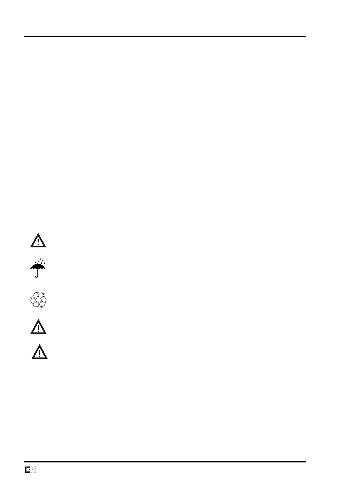
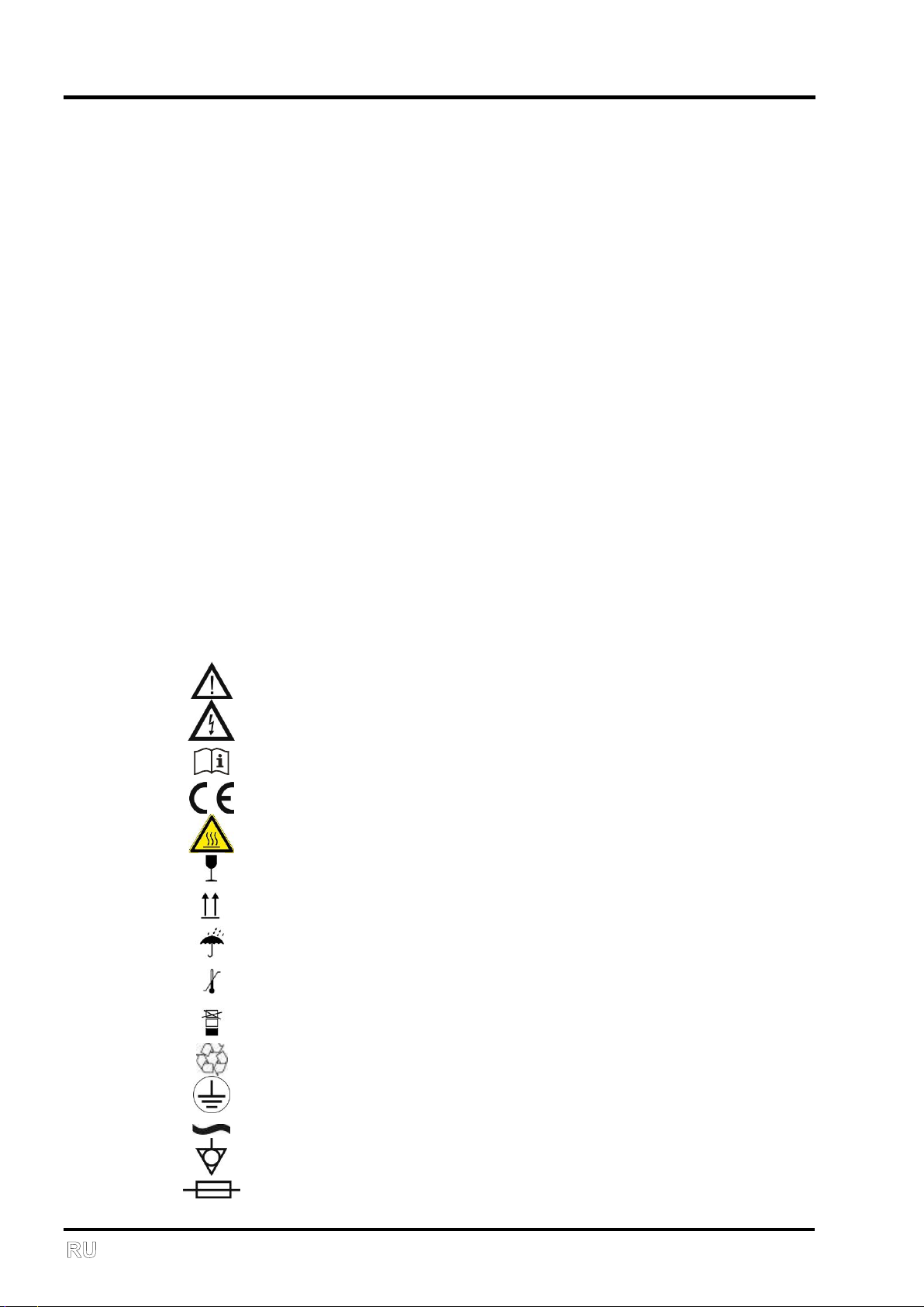
WARNING NOTICES AND SYMBOLS
The following symbols are used for important information in the Installation,
Operation and Maintenance Manual and on packaging and the product:
Attention, see instructions for use
Caution, risk of electric shock
Consult instructions for use
CE mark of compliance
Caution, hot surface
Handling mark on package – FRAGILE
Handling mark on package – THIS SIDE UP
Handling mark on package – KEEP DRY
Handling mark on package – TEMPERATURE LIMITATIONS
Handling mark on package – LIMITED STACKING
Mark on package – RECYCLABLE MATERIAL
Alternating current
Ground connection
Equipotentiality
Fuse
GENERAL INFORMATION
6 NP-eVENT-16_10-2018
USE
• The equipment can only be installed and operated in a dry, ventilated and
dust-free area. Climatic conditions for operation - see Technical data.
• The compressor must stand on a flat and stable base.
• The compressor must not be exposed to rain. The equipment must not be
used in humid or wet environments. Never use the compressor in the
presence of flammable liquids or gases.
• Before connecting the compressor to respiration equipment, make sure
that it meets the requirements of the respiration equipment. Refer to the
Technical data for this purpose.
• Any use other than the compressor‘s intended use is not considered to be
safe. The manufacturer is not responsible for any damages that result if
the compressor is used for any other purpose. Risk is exclusively
assumed by the operator/user.
STORAGE AND TRANSPORT
The compressor is shipped from the factory in transport packaging with the
pump stabilized, protecting it from damage during transport.
For transport, always use the original packaging and secure the compressor
in the upright position.
Protect the compressor from humidity, contamination and extreme
temperatures during transport and storage. A compressor in its original
packaging should be stored in a warm, dry and dust-free area.
Keep the packaging material, if possible. If not, dispose of the packaging
material in an environmentally-friendly way. Cardboard can be recycled.
Before moving or transporting the compressor, the pressure in the air tank
and hoses must be released and any condensed water must be drained.
Secure the motor to prevent movement before shipping.
Prior to transport it is necessary to secure the motor inside the
compressor (Chapter 5)

EQUIPMENT DESCRIPTION
NP-eVENT-16_10-2018 7
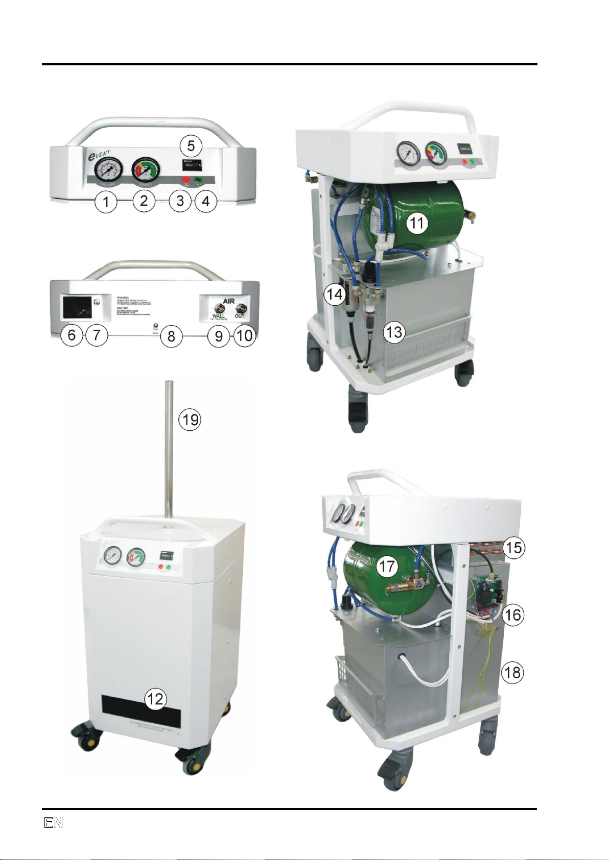
2. EQUIPMENT DESCRIPTION
1. PRESSURE - output air pressure gauge (accuracy ± 5%)
2. HUMIDITY - humidity indicator (performance)
3. Cooling failure indicator
4. Power indicator
5. Hour meter
6. Main input, power switch, primary fuses
7. Equipotential (ground) pin
8. Socket for the electrical cord
9. WALL - inlet air coming from an outside compressed air source
10. OUT - output air from compressor
11. Air tank
12. Suction filter
13. Pressure regulator with filter
14. Filter and water trap
15. Cooler
16. Control electronics
17. Safety valve
18. Internal back cover
19. Tube for supporting equipment
The equipment consists of an oil-free piston compressor driven by a single-
phase electric motor, filtering and drying equipment, an air tank and a
pressure regulator. The compressor is placed in a box lined with noise
absorbing insulation. The equipment produces filtered compressed air
without any traces of oil with reduced water content (dry air).
The air compressor has an input air connector labeled WALL (9) that allows
the connection of an outside air source. When an outside compressed air
source is connected to the WALL inlet fitting supplies air above the adjusted
output pressure, the compressor will not be activated even though the power
switch is in the ON position. Instead, the air from the outside source will be
directed to the compressor's air output. When the outside air source pressure
is less than the adjusted output pressure (or is not connected) and the power
switch is in the ON position, the compressor is activated and supplies
compressed air through the air output.
The compressor pulls in atmospheric air through the suction filter (12).
Compressed air is cooled in the cooler (15), continues to the filter (14) and
condensed liquid from the water trap is automatically released to the
evaporation tray. The air continues through the check valve to the air tank
(11) and through the pressure regulator with the output filter (13) to the OUT
connector (10). Fans operate during compressor operation and when not
operating when the temperature in the cabinet is over 40°C (104°F). If the
temperature in the cabinet is over 80°C (176°F), a cooling failure is signaled
by the red indicator (3) and an acoustic alarm. Control electronics (16) control
compressor operation based on the pressure in the air tank (11). A safety
valve (17) ensure the maximum allowed tank pressure is not exceeded.
EQUIPMENT DESCRIPTION
8 NP-eVENT-16_10-2018
TECHNICAL DATA
NP-eVENT-16_10-2018 9
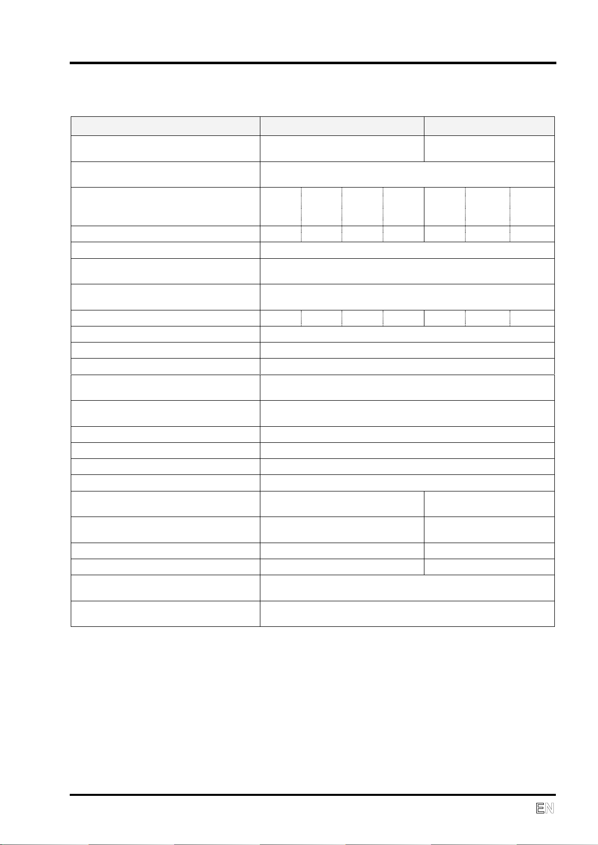
3. TECHNICAL DATA
TYPE
DK50 D
DK50 DM
Output flow at pressure
3.5 bar (51 psig)
Liters/min
40
60
Output flow max.
at pressure 3.5 bar (51 psig)
200 L/min for 2 s *
Rated voltage / Frequency
V/Hz
230/50
230/60
USA
Model
120/60
100
/50-60
230/50
230/60
USA
Model
120/60
Nominal current
A
2.8
2.8
5.6
5,6
3.4
4.3
8.6
Filtration of air to
m
5
Dew point depression at 40 L/min,
3 bar (43.5 psig), 20°C (68°F)
5°C (9°F) under the ambient temperature
Outlet connection
RECTUS 21KS KS08 MPC
Or DISS 1160-A (3/4"-16 UNF)
Sound level
dB(A)
49
51
51
51
50
52
52
Mode of operation
Continuous - S1
Release of condensed water
Automatic
Indication of cooling failure
Acoustic and visual at 80°C (176°F)
Output pressure
3.0 bar (43 psi)
Adjustable to max. 3.5 bar (51 psi)
Automatic start-up
pressure (backup)
3.0 bar (43 psig)
Adjustable to max. 3.5 bar (51 psi)
Air tank capacity
L
5
Pressure range
5.0 - 7.0 bar (72.5 - 101.5 psi)
Safety valve setting
8.0 bar (116 psi)
Adjustment of the output air pressure
Pressure regulator
Dimensions of compressor
w x d x h
400x430x780 mm (16x17x31 in)
400x500x780 mm
(16x20x31 in)
Dimensions of packaging
w x d x h
480x530x835 mm (19x20x33 in)
480x580x835 mm
(19x23x33 in)
Net weight
46 kg (101 lbs)
59 kg (130 lbs)
Gross weight
60 kg (132 lbs)
73 kg (161 lbs)
Implementation pursuant to
EN 60601-1, EN 12021
Class I.
Classification acc. to MDD 93/42
EEC, 2007/47 EC
II b
* With 0.6 bar pressure drop (8.7 psi)
Climatic conditions for storage and transport
Temperature –25°C to +55°C (-13°F to +131°F), 24 hrs +70°C (+158°F)
Relative air humidity 10% to 90% (no condensation)
Relative air humidity for seaworthy packing 10% to 100% (with condensation)
Climatic conditions for operation
Temperature +5°C to +40°C (+41°F to +104°F)
Relative air humidity up to +95%
IPX0 Rating
TECHNICAL DATA
10 NP-eVENT-16_10-2018
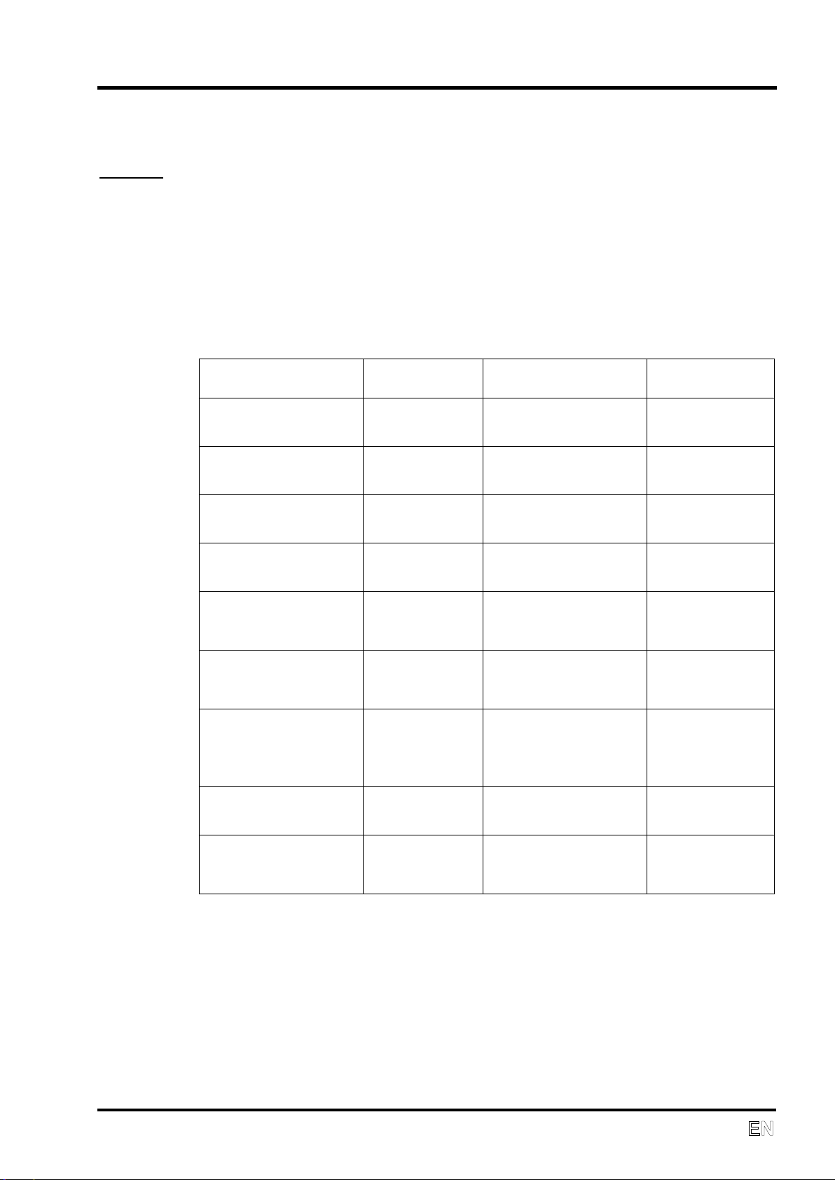
FAD efficiency correction for differences in elevation
FAD correction table
FAD efficiency refers to conditions at an elevation of 0 mamsl:
Temperature: 20°C
Atmospheric pressure: 101325 Pa
Relative humidity: 0%
Elevation [mamsl]
0 - 1500
1501 - 2500
2501 -
3500
3501 -
4500
FAD [l/min]
FAD x 1
FAD x 0.8
FAD x 0.71
FAD x 0.60
OPERATION
NP-eVENT-16_10-2018 11
4. OPERATION
INSTALLATION AND FIRST OPERATION
Do not use the compressor immediately after unpacking as it will not
adjust to the ambient temperature.
Only qualified personnel can install the compressor and put it into
operation for the first time. The installer shall train the operating
personnel in the use and routine maintenance of the equipment.
Installation and training of personnel should be acknowledged by the
installer‘s signature on the installation certificate.
Prior to start-up, the four screws for transport stabilization must be
removed. If the compressor is switched on without removing the
stabilizers, the compressor could be permanently damaged!
The compressor does not contain a backup power supply.
This compressor can only be used with ventilators equipped with low
pressure alarms.
Never block the suction filter and the vent outlets on the lower part of
equipment. Never lift the unit by the handle! The handle is to be used to
move a compressor on the floor with the brakes released.
If the compressor is equipped with a main source of air, the standby air
source must be available.
ANY MODIFICATION OF THIS EQUIPMENT IS FORBIDDEN!
If this equipment is used nearby other instruments, the equipment must
be observed in order to verify normal operations in the configuration it
will be used.
Instruments may be affected electro-magnetically!
Preparing the compressor for use
After unpacking, place the compressor upright with the castor wheels firmly
on the ground.
OPERATION
12 NP-eVENT-16_10-2018
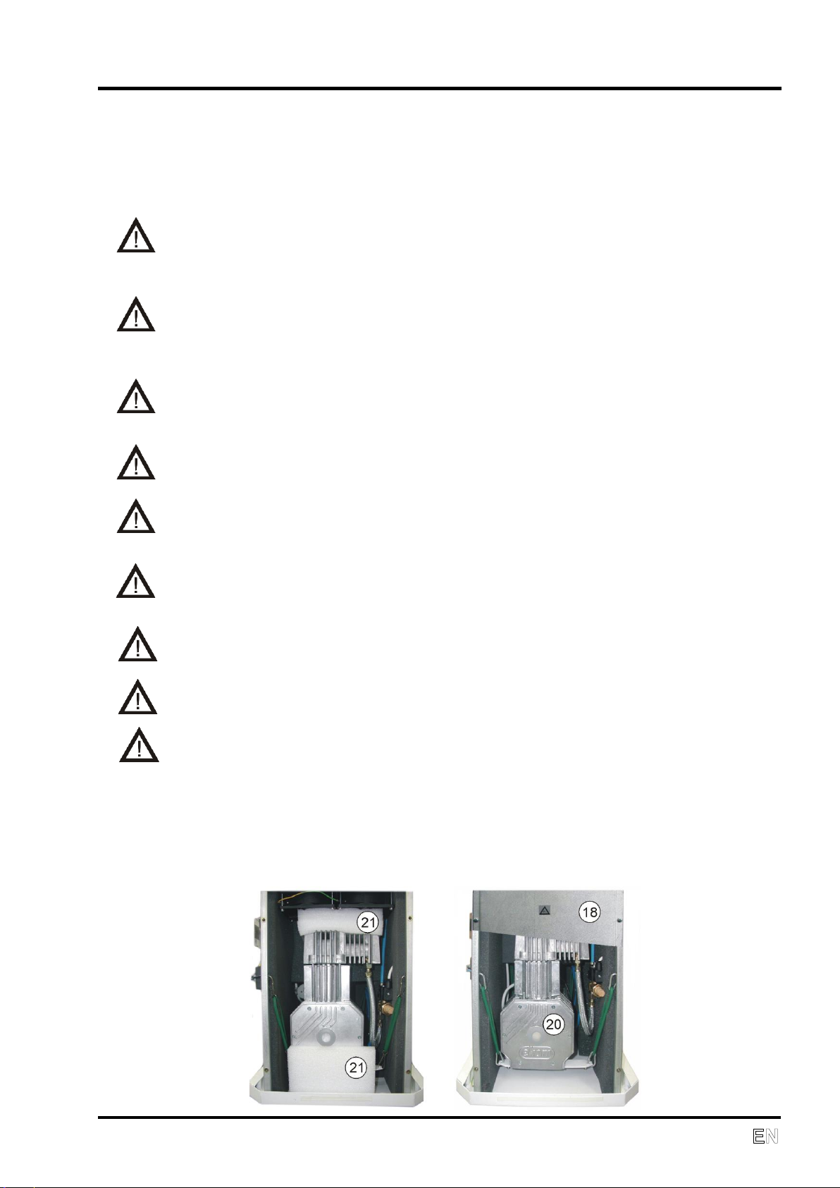
• Remove the front and back cover unscrewing the six screws on the
cabinet side.
• Unscrew the four screws and remove the internal back cover (18).
• Remove all packing elements above (21) and under the compressor (20).
• Screw the internal back cover back on, connect the ground wire, screw
the front and back cover and insert the suction filter.
Please retain the packing elements for future compressor transportation.
Compressed air connection
The medical compressor is equipped with quick couplings WALL (9) and
OUT (10) to the rear of the cabinet.
Connect the pressure hose from the given equipment/respiration equipment
to the quick coupling OUT (10) -outlet compressed air.
Connect the compressed air line from the central distribution line o the quick
coupling WALL (9) -inlet compressed air. Air from the distribution system is
automatically connected through the compressor to the OUT outlet port. In
this configuration, the compressor serves as a backup source of compressed
air. If the air pressure from the central distribution system is reduced, the
compressor automatically switches on and there is no interruption in the
supply of continuously pressurized air at the outlet of the compressor.
Please note that the air supply from the central distribution line
entering the compressor must be medical grade air (particulate size,
humidity.) The compressor does not modify the air from the central
distribution line.
The hose connecting the compressor to the respiration equipment
must not pass through a cold environment i.e. placed on the ground. It
should be as short as possible with no kinks (this may cause water to
condense inside the hose).
Electrical connection
The compressor comes with a plug containing an appropriate
protective contact (ground.) Adhere to local electrical regulations. The
voltage and frequency of the mains must comply with the
specifications on the data label.
The electrical cord must not be stressed or have any tension exerted
upon it, and must always be free.
• The socket must be accessible for safety reasons so that the equipment
can be safely disconnected in case of an emergency.
• The relevant current circuit must be protected.
OPERATION
NP-eVENT-16_10-2018 13
• Connection of the ground connection (7) to other equipment must adhere
to local electrical regulations.
• Fasten the electrical cord through the holder (8).
First operation
• Make sure the stabilizing screws used during transport were removed.
• Check that the connection to the compressed air supply is correct.
• Check for proper connection to the main power supply.
• Switch on the pressure switch (6) to position “I”.
After the compressor is first put into operation, the air tank of the compressor
is pressurized to a ‘switching-off’ pressure and the compressor will then be
automatically switched off. During the following time period the compressor
works in an automatic mode, i.e. according to the consumption of
compressed air; the pressure switch controls compressor operation.
During operation, the equipment releases condensed water from the
condenser (filter) automatically to the evaporation tray.
Accessories
Holder for supporting equipment - Item 604011346-000
The holder (19) is suitable for supporting a respiratory apparatus with
accessories. Please remove the plug in the middle of the upper side before
installation. Screw the holder into the socket and tighten it fast.
Technical data:
Diameter 25 mm
Height 1100 mm above the floor
The maximum holder load is 28 kg. The centre of gravity of supporting
equipment must be in the axis of the holder, max. 1100 mm above the floor.
Consult the manufacturer regarding any other connections.
The manufacturer is not liable for any damage resulting from excessive
loads on the equipment!
The supplier is obliged to ensure the acceptability of a load delivered
by a supplied accessory.
It is forbidden to lean or press against an installed accessory for
support!
The equipment must be lifted when travelling over an obstacle!
Supporting equipment must be disassemble before transport!
OPERATION
14 NP-eVENT-16_10-2018
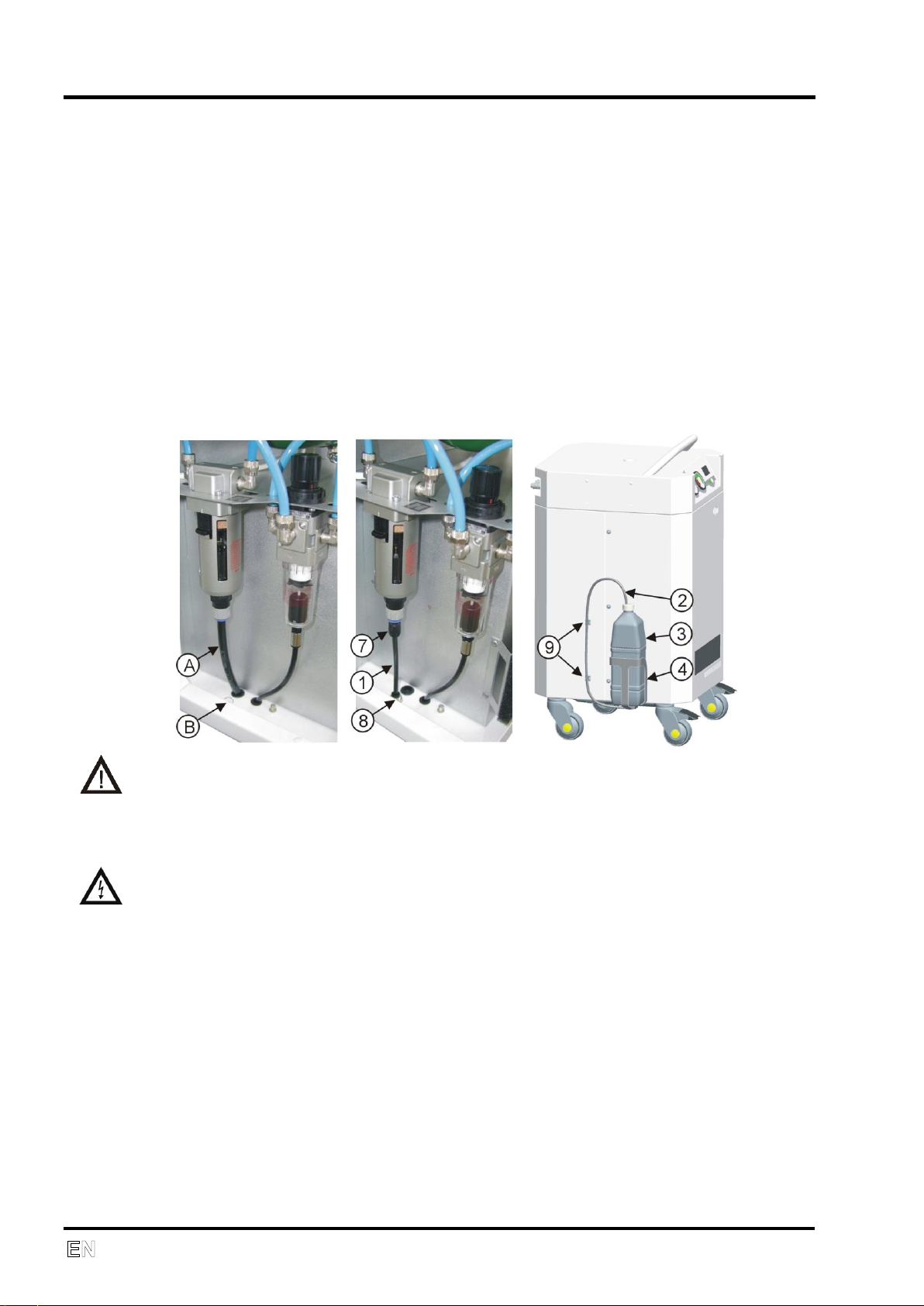
Kit for higher relative air humidity - Item 604011497-000
1. Hose PUR 6/4-130 062000337-000 1
2. Hose PUR 6/4-700 062000357-000 1
3. Tank LUH-1 062000333-000 1
4. Holder 3KB-972 023000564-000 1
5. Washer D5 043000002, 043000005-000 4
6. Screw M5 041000131-000 4
7. Reducer 10/6 062000339-000 1
8. Connector L6/6 025400153, 025400154-000 1
9. Clamp self-adhesive 033400011-000 2
Dismount the hose (A) and plug (B). Install the reducer (7), connector (8) and
plug-in hose (1). Screw holder (4), plug-in hose (2) and install tank (3). Fix
hose with two clamps (9).
Empty tank regularly.
OPERATION
In case of emergency, switch the equipment off at the switch and pull
out the main power plug.
Automatic operation. When the pressure in air tank falls to the ‘switch on’
pressure, the compressor is automatically switched on. The compressor is
automatically switched off when the pressure increases to the ‘switch off’
pressure in the air tank.
Switching on the compressor
The compressor is switched on at the main power switch (6) by putting it in
position "I". Switching on is signaled by the green indicator (4).
OPERATION
NP-eVENT-16_10-2018 15
Running the compressor
When the pressure of the air at the ‘Inlet’ port is reduced or if there is a
reduction of pressure in the air tank, the compressor is switched on and the
air tank is filled with compressed air. After the ‘switch-off’ pressure is
reached, the compressor is automatically switched off. Pressure of the output
air from compressor is indicated on the pressure gauge (1).
During compressor operation, the pointer of the humidity indicator (2) should
be in the green zone. If equipment air consumption is higher than maximum
output, the pointer of indicator will move from the green zone and the air from
compressor will not reach the declared parameters (see Technical data).
The hour meter (5) indicates total running time of the compressor.
Cleaning the suction filter
At least once a week take out and clean the suction filter (12) located on the
front side. Wash the filter in warm soapy water, rinse thoroughly and allow it
to dry. Insert the clean filters so that the suction openings are completely
covered by the filters.
Cooling failure alarm
Problems with compressor cooling are signaled by the red indicator (3) and
the acoustic alarm.
If a cooling failure alarm is signaled, secure an alternate air pressure
source and disconnect the compressor.
Cleaning the compressor
The product can be cleaned using normal detergents. To clean the
compressor, use a detergent that contains no abrasives, chemical solvents
or other corrosive agents.
MAINTENANCE
16 NP-eVENT-16_10-2018
5. MAINTENANCE
REPAIRS AND SERVICE
Warranty and extended warranty repairs are to be completed by the
manufacturer or a service provider authorized by the manufacturer.
The manufacturer reserves the right to modify the equipment in any
way that will not alter the function or the operation of the equipment.
Only a qualified technician or the Customer Service Department of the
manufacturer may perform repairs that go beyond routine maintenance.
Use only spare parts and accessories approved by the manufacturer.
Prior to any maintenance or repairs, switch off the compressor and
disconnect it from the mains (pull out the main power plug).
MAINTENANCE
NP-eVENT-16_10-2018 17
MAINTENANCE SCHEDULE
NOTICE
The operating entity is obliged to ensure that all tests of the equipment are carried
out repeatedly at least once within every 24 months (EN 62353) or in intervals as
specified by the applicable national legal regulations. A report must be prepared on
the results of the tests (e.g.: according to EN 62353, Annex G), including the
measurement methods used.
Maintenance range
Page
Time interval
To be
performed by
Clean suction filter
13
At least once a
week
Staff
Safety valve check
16
Once per year
Qualified expert
Replace filter (B)
16
Every 8000 hours
Qualified expert
Replace filter in
blow down filter (C)
16
Every 2000 hours
Qualified expert
Replace filter in the
pressure regulator
(D)
17
Every 2000 hours
Qualified expert
Test the tightness of
joints and inspect
the equipment
Service
documentation
After two years
Qualified expert
Replace piston
complete with piston
rings, O-rings and
bearing
Service
documentation
Every 4000 hours
Qualified expert
Bearing
replacement
Service
documentation
Every 4000 hours
Qualified expert
Perform “Repeated
Test” according to
EN 62353
15
1 x 2 years
Qualified expert

MAINTENANCE
18 NP-eVENT-16_10-2018
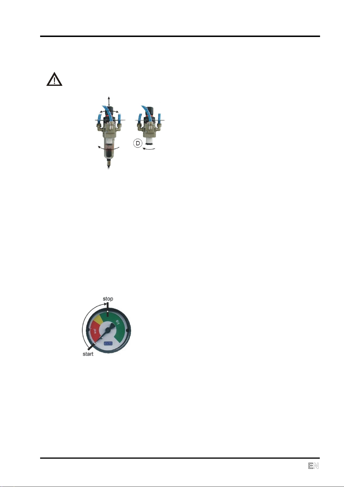
Safety valve check
The safety valve is adjusted to 8 bar (116 psig) by the manufacturer,
then tested and marked. It must not be readjusted.
• Turn the screw of the safety valve
(17) several rotations to left until the
safety valve puffs.
• Only allow the safety valve freely
puff for a short period of time.
• Turn the screw to the right until it is
tight, closing the valve.
Never use the safety valve to release pressure in the air tank. This could
damage the safety valve.
Replacing the suction filter
• Unlock the cover and pull it out.
• Replace the filter
• Lock the cover
Spare part:
Suction filter 05W POLYESTER, Item 025200194-000
Replacing the blow down filter
• Loosen lock on filter (14) by pulling it down.
• Slightly turn the cover of the filter and pull it out.
• Unscrew the filter holder.
• Replace filter (C), screw in the filter holder.
• Place the cover of filter and secure it by turning to right till it locks.
B
MAINTENANCE
NP-eVENT-16_10-2018 19
Replacing the pressure regulator filter
Before working on this equipment all air pressure must be released
from the tank so that pressure is zero and the equipment must be
disconnected from the electrical power mains.
• Unscrew the filter regulator cover (13) and pull it out.
• Unscrew the filter holder.
• Replace filter (D), screw in the filter holder.
• Screw in the regulator cover.
Setting output air pressure
Switch on the compressor and set the output pressure air flow until the
humidity indicator (2) remains in the green area. Unlock the control button of
the filter regulator (13) and rotate to set the demand output pressure. After
setting the pressure, lock the control button of the regulator by pushing down.
Capacity check
Before checking capacity it is necessary to switch off the compressor using
the power switch, vent air pressure out of the air tank and disconnect the
output hose from the OUT (10) fitting. Next switch the compressor on using
the power switch and measure (record) the time between start and stop (2).
Compressor capacity is met when the recorded time is not more than 45
seconds for DK50 D or 30 seconds for DK50 DM.

MAINTENANCE
20 NP-eVENT-16_10-2018
Stabilizing the compressor before shipping
Before shipping, the compressor must be stabilized to prevent movement.
The procedure is illustrated on page 9.
• Remove the front and back covers unscrewing screws on the cabinet side,
disconnect the ground connector on the covers.
• Disassemble the internal back cover (18) unscrewing four screws.
• Insert the shipping elements (21) under and above the compressor.
• Assemble the internal back cover (18), connect the ground connector on
the covers, and insert the covers and the suction filter.
SHUTDOWN
If the compressor is not going to be used for a long period of time,
disconnected it from the main power supply and release the pressure in the
air tank.
EQUIPMENT DISPOSAL
• Disconnect the equipment from the main power supply.
• Release the pressure in the air tank.
• Dispose of the equipment according to local regulations.
• Parts used in this product have no negative impact on the environment
when disposed of properly.
TROUBLESHOOTING
NP-eVENT-16_10-2018 21
6. TROUBLESHOOTING
Prior to servicing the equipment, reduce the pressure in the air tank to
zero and disconnect the equipment from the main power supply.
Only trained service personnel can perform the activities listed in the
troubleshooting guide.
PROBLEM
POTENTIAL CAUSE
TROUBLESHOOTING
Compressor
does not start
No main power voltage
Switched off main breaker in distribution
system
No current from the pressure
switch
Check supply
Replace a defective fuse
Loose wire terminal – tighten
Power cord defective – replace
Interrupted winding of motor,
damaged thermal protection
Replace motor
Defective capacitor
Replace capacitor
Jammed piston or another parts
Replace damaged parts
Pressure switch does not switch
on
Change pressure switch
The humidity
indicator is out
of the green
zone
Leakage of air from pneumatic
distribution system
Inspect pneumatic distribution system –
seal loose connection
Large consumption of
compressed air
Do not exceed max. flow (see Technical
data)
Compressor
often switches
on
Leakage of air from pneumatic
distribution system
inspect pneumatic distribution system –
seal loose connection
Leakage of check valve
Clean check valve, replace seal,
replace check valve
The operation
of compressor
is extended
Leakage of air from pneumatic
distribution system
Inspect pneumatic distribution system –
seal loose connection
Worn out piston rings
Replace worn out piston rings
Dirty filter inserts
Replace the dirty inserts
Red indication
lights – state
of overheating
Dirty suction filter
Clean or replace the dirty suction filter
Dirty filter inserts
Replace the dirty inserts with new ones
Cooling fans don’t work
Replace fans or faulty thermal switch
Unit is hot, unventilated area
Relocate unit
Compressor is
noisy
(knocking,
metal noises)
Damaged piston bearing or
bearing on motor
Replace damaged bearing
Loose (cracked) belt on the
compressor hanger
Replace damaged hanger
Water coming
out of outlets
Water trap (13) or (14) not
working
Clean or replace the water trap

SPARE PARTS
22 NP-eVENT-16_10-2018
7. Spare parts
• Suction filter (12) 4KB-552 025000011-000
• Suction filter (B) 05W POLYESTER 025200194-000
• Filter (C) 111511-40B 025200070-000
• Filter (D) AF20P-060S 025200113-000
• Fuse
• DK50 D 230V T6.3A 038100004-000
• DK50 D 120V, DK50 DM 230V T10A
038100005
• DK50 DM 120V T16A 038100007-000
• Nipple
• RECTUS 21SSTF08MPC 025500131-000
• DISS 1160-A 024000261-000
ELECTRIC AND PNEUMATIC DIAGRAMS
NP-eVENT-16_10-2018 23
EV1 EV2
YV1
1 2 3
40°C
ST1
4 5 6 7 8 9 10 11 12 13 14
HL2
80°C
ST2
HL1
RD
GN
1
gnye
bk
gy
bn
M1
M
Motor Soft Start-Stop
PCB
PE
U N
PH
0000
h
C
B1
1/N/PE ~ 115/230 V 50/60 Hz
ELECTRIC OBJECT OF 1st CAT.
XC
EV1 EV2
YV1
1 2 3
40°C
ST1
4 5 6 7 8 9 10 11 12 13 14
HL2
80°C
ST2
HL1
RD
GN
Motor Soft Start-Stop
PCB
PE
U N
PH
0000
h
1/N/PE ~ 115/230 V 50/60 Hz
ELECTRIC OBJECT OF 1st CAT.
XC
M1
1
M
B1
C
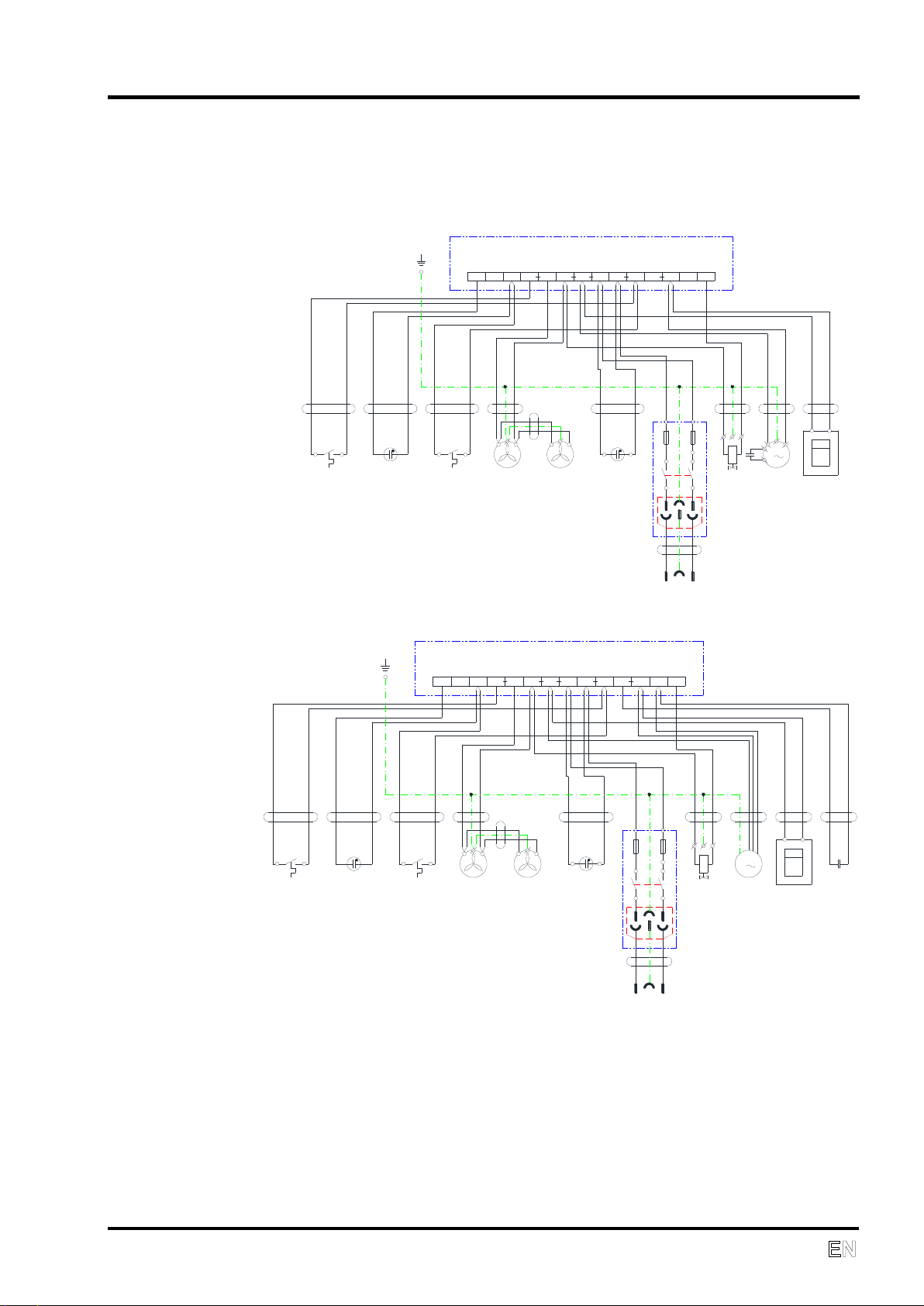
8. ELECTRIC AND PNEUMATIC DIAGRAMS
WIRING DIAGRAM
DK50 D
DK50 DM
Note
Wire entering the terminal should be marked with marking element with corresponding
number.
Des. Name Des. Name
HL1,HL2 Glow lamp M Electric motor
EV1,EV2 Ventilator ST1,ST2 Thermal switch
PH Hour meter XC Socket with fuses
YV Solenoid valve Cb1 Capacitor
ELECTRIC AND PNEUMATIC DIAGRAMS
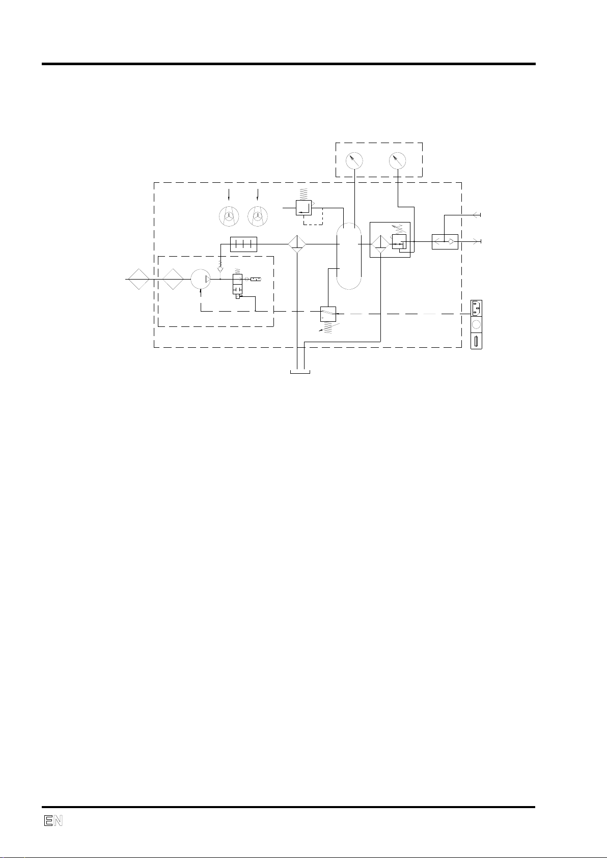
24 NP-eVENT-16_10-2018
PNEUMATIC DIAGRAM
2
1
19
3
4
6
8
5
18
18
13
14
9
7
17
10
12
WALL
20
OUT
11
15 16
CONTROL PANEL
1. Suction filter
2. Suction filter
3. Compressor
4. Solenoid valve
5. Sound absorber
6. Cooler
7. Micro filter with water trap
8. Check valve
9. Air tank
10. Pressure regulator with filter
11. Air Outlet
12. Air Inlet
13. Main input, power switch, primary fuses
14. Pressure sensor
15. Humidity indicator
16. Pressure gauge
17. Pressure relief valve
18. Fan
19. Water tray
20. Shuttle valve

СОДЕРЖАНИЕ
NP-eVENT-16_10-2018 25
СОДЕРЖАНИЕ
1. ОБЩИЕ CВЕДЕНИЯ .............................................................................................................. 26
ПРИМЕНЕНИЕ СОГЛАСНО НАЗНАЧЕНИЮ ................................................................... 26
ПРОТИВОПОКАЗАНИЯ И ПОБОЧНЫЕ ЭФФЕКТЫ ........................................................ 26
ОТВЕТСТВЕННОСТЬ ПЕРСОНАЛА ЗА БЕЗОПАСНОСТЬ ПАЦИЕНТА ...................... 26
МАРКИРОВКА ................................................................................................................... 26
ПРЕДУПРЕЖДЕНИЯ ........................................................................................................ 26
Общие предупреждения по безопасности ............................................................ 27
Предупреждения по безопасности для защиты от электрического тока ............. 27
ПРЕДОСТЕРЕГАЮЩИЕ ПРЕДУПРЕЖДЕНИЯ И СИМВОЛЫ ........................................ 28
УСЛОВИЯ ПРИМЕНЕНИЯ ............................................................................................... 29
УСЛОВИЯ ХРАНЕНИЯ И ТРАНСПОРТИРОВКИ ............................................................ 29
2. ОПИСАНИЕ ИЗДЕЛИЯ .......................................................................................................... 30
3. ТЕХНИЧЕСКИЕ ДАННЫЕ .................................................................................................... 32
Поправка эффективности потребляемого объема сжатого воздуха (ПОСВ) на
разность подъема .................................................................................................... 33
4. ОБСЛУЖИВАНИЕ .................................................................................................................. 34
УСТАНОВКА И ПЕРВЫЙ ПУСК В ЭКСПУАТАЦИЮ ........................................................ 34
Отфиксирование компрессора .............................................................................. 35
Присоединение сжатого воздуха ........................................................................... 35
Электрическое присоединение .............................................................................. 36
Первый пуск в эксплуатацию ................................................................................. 36
Дополнительное оснащение .................................................................................. 37
ОБСЛУЖИВАНИЕ ............................................................................................................. 38
Включение компрессора ........................................................................................ 38
Работа компрессора ............................................................................................... 38
Очистка и замена входного фильтра..................................................................... 39
Сигнализация помехи охлаждения ........................................................................ 39
Очистка изделия ..................................................................................................... 39
5. УХОД ...................................................................................................................................... 39
СВЕДЕНИЯ О РЕМОНТНЫХ УСЛУГАХ .......................................................................... 39
ИНТЕРВАЛЫ УХОДА ........................................................................................................ 40
УВЕДОМЛЕНИЕ ................................................................................................................ 40
Проверка предохранительного клапана ................................................................ 41
Замена фильтра ................................................................................................ ..... 41
Замена фильтровального вкладыша фильтрa ..................................................... 41
Замена фильтровального вкладыша регулятора ................................................ 42
Контроль мощности компрессора .......................................................................... 42
Фиксация агрегата перед транспортировкой ........................................................ 43
ПРИОСТАНОВЛЕНИЕ ЭКСПЛУАТАЦИИ ........................................................................ 43
ЛИКВИДАЦИЯ УСТРОЙСТВА .......................................................................................... 43
6. ПОИСК НЕИСПРАВНОСТЕЙ И ИХ УСТРАНЕНИЕ............................................................. 44
7. ЗАПЧАСТИ ............................................................................................................................. 45
8. ЕЛЕКТРИЧЕСКИЕ И ПНЕВМАТИЧЕСКИЕ СХЕМЫ ............................................................ 46
ЕЛЕКТРИЧЕСКАЯ СХЕМА ............................................................................................... 46
ПНЕВМАТИЧЕСКАЯ СХЕМА ........................................................................................... 46
9. ПРИЛОЖЕНИЕ ....................................................................................................................... 92
ОТЧЕТ ОБ УСТАНОВКЕ ................................................................................................... 93

ОБЩИЕ СВЕДЕНИЯ
26 NP-eVENT-16_10-2018
1. ОБЩИЕ CВЕДЕНИЯ
УВАЖАЕМЫЙ ПОЛЬЗОВАТЕЛЬ.
ПОЖАЛУЙСТА, ВНИМАТЕЛЬНО ПРОЧТИТЕ ДАННОЕ РУКОВОДСТВО ПО ЭКСПЛУАТАЦИИ ДЛЯ
ТОГО, ЧТОБЫ ОБЕСПЕЧИТЬ ОПТИМАЛЬНОЕ И ПРАВИЛЬНОЕ ФУНКЦИОНИРОВАНИЕ ВАШЕГО
МЕДИЦИНСКОГО ОБОРУДОВАНИЯ.
Изделие зарегистрировано и соответствует требованиям Федеральной Службы по
надзору в сфере здравоохранения и социального развития Российской Федерации.
Изделие соответствует системе сертификации ГОСТ Р Госстандарта России.
ПРИМЕНЕНИЕ СОГЛАСНО НАЗНАЧЕНИЮ
Медицинский компрессор DK50 D, DK50 DM в передвижном шкафчике
служит в качестве источника чистого, безмасляного, сжатого воздуха
для дыхательного оборудования.
ПРОТИВОПОКАЗАНИЯ И ПОБОЧНЫЕ ЭФФЕКТЫ
Противопоказания или побочные эффекты неизвестны.
ОТВЕТСТВЕННОСТЬ ПЕРСОНАЛА ЗА БЕЗОПАСНОСТЬ ПАЦИЕНТА
Инструкция по установке, обслуживанию и уходу является составной
частью устройства. Необходимо, чтобы она находилась всегда рядом с
устройством. Точное соблюдение настоящей инструкции является
предпосылкой правильного применения согласно назначению и
правильного обслуживания устройства.
МАРКИРОВКА
Продукты обозначены маркой согласия CE, исполняют директивы
безопасности Европейской унии (93/42/EEC).
ПРЕДУПРЕЖДЕНИЯ
• Безопасность обслуживающего персонала и бесперебойная
эксплуатация устройства гарантированы только при использовании
оригинальных составных частей устройства. Применять только
принадлежности и запчасти, указанные в технической документации
или непосредственно одобренные производителем.
• Если будут применяться иные принадлежности или расходный
материал, производитель не может принять на себя никакую
гарантию за безопасную эксплуатацию и безопасную работу.
• На повреждения, которые возникли при применении иных
принадлежностей или расходного материала, чем тех, которые
предписывает или рекомендует производитель, гарантия не
распространяется.

ОБЩИЕ СВЕДЕНИЯ
NP-eVENT-16_10-2018 27
• Производитель берет на себя ответственность по отношению к
безопасности, надежности и работе только тогда, когда:
- установку, новую настройку, изменения, расширения и ремонты
осуществляет производитель или представитель - сервисная
организация, уполномоченная производителем,
- устройство применяется в соответствии с инструкцией по установке,
обслуживанию иуходу.
• Инструкция по установке, обслуживанию и уходу соответствует при
распечатке варианту устройства и состоянию согласно
соответствующим техническим нормам по безопасности.
Производитель оставляет за собой все права по патентной охране
указанных соединений, методов и названий.
Общие предупреждения по безопасности
Производитель разработал и сконструировал устройство таким
образом, чтобы были исключены повреждения при правильном
применении по назначению. Производитель считает своей
обязанностью описать следующие меры по безопасности, чтобы можно
было исключить остальные повреждения.
• При эксплуатации устройства необходимо принимать во внимание
законы и региональные инструкции, действующие по месту
назначения. В интересах безопасного проведения работ за
соблюдение инструкций несут ответственность эксплуатирующее
лицо и пользователь.
• Оригинальную упаковку необходимо сохранить на случай возможного
возвращения. Только оригинальная упаковка гарантирует
оптимальную защиту устройства во время транспортировки. Если в
течение гарантийного срока необходимо вернуть устройство,
производитель не гарантирует за повреждения, нанесенные в
результате неправильной упаковки.
• Если непосредственно в связи с эксплуатацией устройства настанет
нежелательная ситуация, пользователь обязан без промедления
информировать своего поставщика об этой ситуации.
• Изделие не предназначено для эксплуатации во взрывоопасных
областях. Взрывоопасность угрожает при использовании
компрессора в близости огнеопасных анестезирующих средств.
• Никонда недавайте кислород или закись азота в компрессор.
Електрические компоненты изделия неурочные для их
использование.
• Устройство можно использовать только с аппаратом ИВЛ
оборудованным сигнализацией низкого давления.
Предупреждения по безопасности для защиты от электрического тока
• Оборудование может быть присоединено только к правильно
установленной розетке с защитным соединением. Доверительное
ОБЩИЕ СВЕДЕНИЯ
28 NP-eVENT-16_10-2018
заземление одержите тогда когда ест устройство присоединене в
розетку эквипотенциального соединения.
• Перед присоединением устройства необходимо проверить,
соответствуют ли сетевое напряжение и частота, указанные на
устройстве, значениям сети питания.
• Перед пуском в эксплуатацию необходимо проверить возможные
повреждения устройства и подсоединяемых воздушных
распределительных сетей. Поврежденные проводки и вилки сразу
же необходимо заменить.
• В случае опасных ситуаций или технических неисправностей,
устройство надо сразу же отсоединить от сети ( вытащить сетевой
штепсель).
• Во время всех работ, связанных с ремонтом и уходом, должны быть
сетевой штепсель вынут из розетки, из напорного трубопровода
выпущен воздух и выпущено давление из напорного резервуара.
• Устройство должен устанавливать только квалифицированный
работник.
ПРЕДОСТЕРЕГАЮЩИЕ ПРЕДУПРЕЖДЕНИЯ И СИМВОЛЫ
В инструкции по установке, обслуживанию и уходу, на упаковках и
изделии для особо важных сведений применяются следующие
наименования или знаки:
Внимание! Cмотри инструкции по применению
Внимание! Oпасноcть ранения электрическим током
Читайте инструкцию по применению
CE – обозначение
Внимание! Горячая поверхность
Манипуляционный знак на упаковке – ХРУПКИЙ ПРЕДМЕТ
Манипуляционный знак на упаковке – ЭТОЙ СТОРОНОЙ
ВВЕРХ
Манипуляционный знак на упаковке – БЕРЕЧЬ ОТ ВЛАГИ
Манипуляционный знак на упаковке – ТЕМПЕРАТУРНЫЕ
ОГРАНИЧЕНИЯ
Манипуляционный знак на упаковке – ОГРАНИЧЕННОЕ
СТОГОВАНИЕ
Знак на упаковке – УТИЛИЗИРОВАННЫЙ МАТЕРИАЛ
Присоединение защитного провода
Переменный ток
Клемма для эквипотенциального прямого соединения
Предохранитель
 Loading...