

EKOM DK50 DE User Manual

CONTENTS
CONTENTS
1. GENERAL INFORMATION ...................................................................................................... 5
INTENDED USE .................................................................................................................. 5
CONTRAINDICATIONS AND SIDE-EFFECTS ................................................................... 5
OPERATOR'S RESPONSIBILITY FOR PATIENT SAFETY ................................................ 5
MARKINGS ......................................................................................................................... 5
WARNINGS ........................................................................................................................ 5
General safety warnings ............................................................................................ 6
Electrical system safety warnings .............................................................................. 6
WARNING NOTICES AND SYMBOLS ................................................................................ 7
USE ..................................................................................................................................... 8
STORAGE AND TRANSPORT ........................................................................................... 8
2. EQUIPMENT DESCRIPTION ................................................................................................... 9
3. TECHNICAL DATA .................................................................................................................11
4. OPERATION ...........................................................................................................................13
INSTALLATION AND FIRST OPERATION ........................................................................13
Removal of transport stabilizers ...............................................................................13
Wheel installation .....................................................................................................14
Compressed air connection ......................................................................................14
Electrical connection.................................................................................................14
First operation ..........................................................................................................15
Accessories ..............................................................................................................16
OPERATION ......................................................................................................................16
Switching the compressor on ....................................................................................16
Running the compressor ..........................................................................................17
Cleaning and replacing filters ...................................................................................17
Cleaning the compressor ..........................................................................................17
5. MAINTENANCE ......................................................................................................................18
REPAIRS AND SERVICE...................................................................................................18
Cover removal ..........................................................................................................18
MAINTENANCE SCHEDULE .............................................................................................18
Safety valve check ...................................................................................................19
Checking tightness of joints and inspecting the equipment .......................................20
Replacing filter elements ..........................................................................................20
Setting output air pressure .......................................................................................21
Cleaning the pressure regulator ...............................................................................21
Replacing the suction filter (18) ................................ ................................................21
Stabilizing the compressor before shipping ..............................................................22
SHUTDOWN ......................................................................................................................22
EQUIPMENT DISPOSAL ...................................................................................................22
6. TROUBLESHOOTING.............................................................................................................23
7. SPARE PARTS .......................................................................................................................24
8. ELECTRIC AND PNEUMATIC DIAGRAMS ............................................................................25
WIRING DIAGRAM ............................................................................................................25
PNEUMATIC DIAGRAM .....................................................................................................26
9. ELECTROMAGNETIC COMPATIBILITY DECARATION ........................................................27
NUTZUNGSBESTIMMUNG ...............................................................................................31
10. ANNEX .................................................................................................................................. 111
INSTALLATION RECORD................................................................................................ 111
4 NP-DK50 DE-18_02-2019

GENERAL INFORMATION
1. GENERAL INFORMATION
INTENDED USE
The EKOM DK50 DE is a medical air compressor that supplies clean, oil-free
compressed air for use with medical ventilators.
CONTRAINDICATIONS AND SIDE-EFFECTS
There are no contraindications or side-effects known.
OPERATOR'S RESPONSIBILITY FOR PATIENT SAFETY
The Installation, Operation and Maintenance Manual is an integral part of the
equipment and must be kept with the compressor. Careful review of this
manual will provide information necessary for correct operation of the
equipment.
Rx only
US Federal law restricts the sale of this device by or on the order of a
physician.
MARKINGS
WARNINGS
Products marked with the CE mark of compliance meet the safety
requirements of the European Union (93/42/EEC).
The safety of operating personnel and trouble-free operation of the
equipment are ensured only if original parts are used. Only accessories
and spare parts mentioned in the technical documentation or expressly
approved by the manufacturer can be used.
If any other accessories or consumable materials are used, the
manufacturer cannot be held responsible for the safe operation and
functionality of the equipment.
The warranty does not cover damages resulting from the use of
accessories or consumable materials other than those recommended by
the manufacturer.
The manufacturer assumes responsibility for the safety, reliability and
function of the equipment only if:
- Installation, calibration, amendments, extensions and repairs are
performed by the manufacturer, one of its representatives or a service
provider authorized by the manufacturer
- The equipment is used in accordance with the Installation, Operation and
Maintenance Manual
NP-DK50 DE-18_02-2019 5

GENERAL INFORMATION
The Installation, Operation and Maintenance Manual accurately describes
the design of the compressor and its compliance with safety and technical
standards. The manufacturer reserves all rights to its wiring diagrams,
procedures and names.
General safety warnings
The equipment is designed to operate safely when used correctly. Please
note the following safety measures to avoid injury or damage.
Equipment operation must comply with all local codes and regulations.
Original packaging should be kept for the possible return of the unit. Only
original packaging ensures optimal protection of the equipment during
transport. If it is necessary to return the equipment during the warranty
period, the manufacturer is not liable for damages caused by incorrect
packaging.
The user must immediately notify the supplier if any problem occurs during
the use of the equipment.
This product is not intended for use in areas where there is a risk of an
explosion. Do not operate the compressor in the presence of flammable
anesthetics.
Never feed oxygen or nitrous oxide into the compressor. Compressor
components are not approved for oxygen or nitrous oxide use.
Electrical system safety warnings
The equipment must be connected to ground. I order to assure proper
grounding, connect the compressor to a receptacle marked "hospital
grade."
Before the compressor is plugged in, make sure that the voltage and
frequency of the mains specified on the equipment are the same as the
power mains.
Before operating, check for possible damage to the equipment and any
connections. Damaged pneumatic and electrical lines must be replaced
immediately.
If a technical failure occurs, immediately disconnect the equipment from
the mains (pull out the main power plug).
During repairs and maintenance, ensure that:
- The main power plug is removed from the power socket
- Compressed air lines are disconnected
- All pressure has been released from the air tank
Only a qualified technician can install this equipment.
6 NP-DK50 DE-18_02-2019
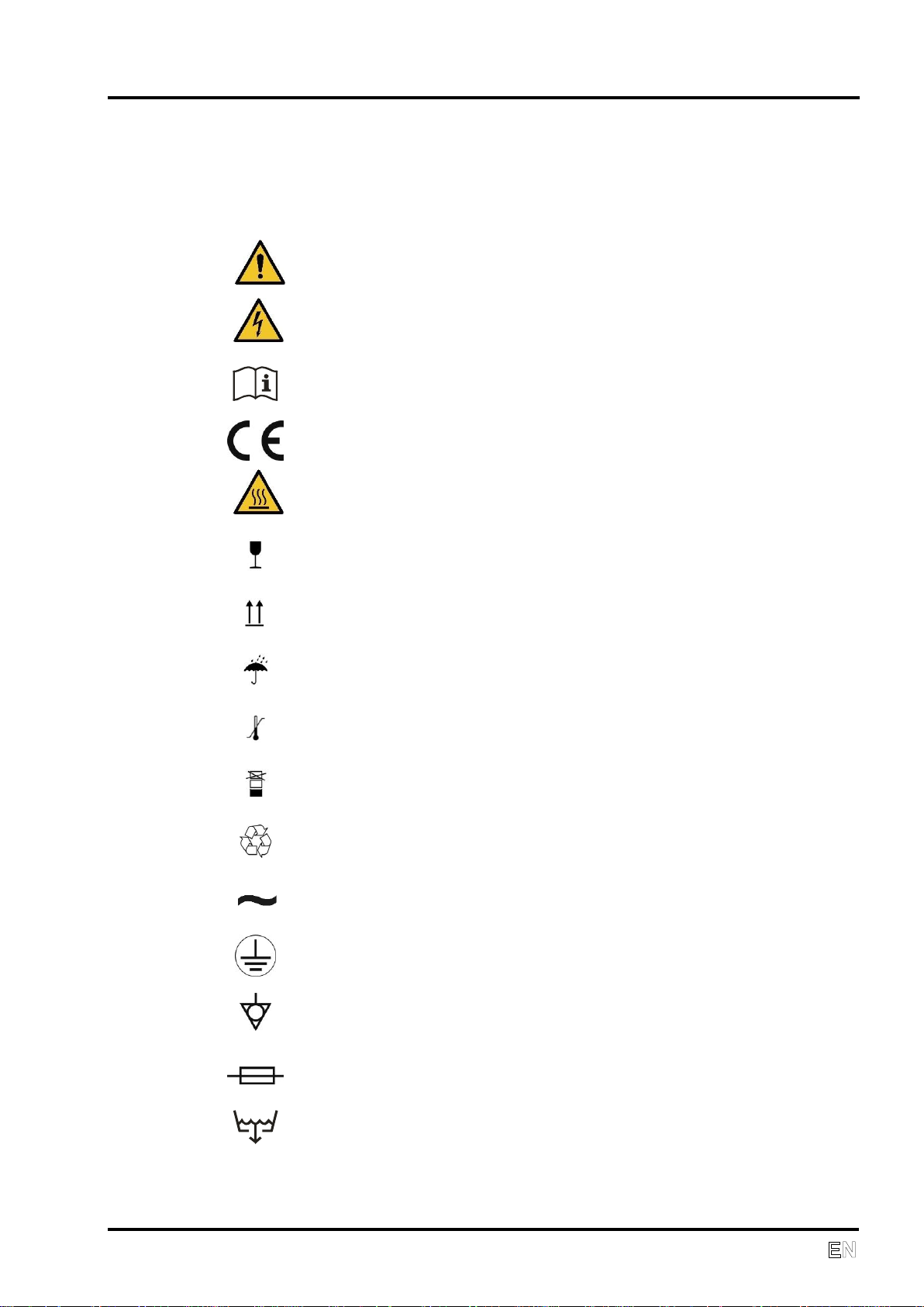
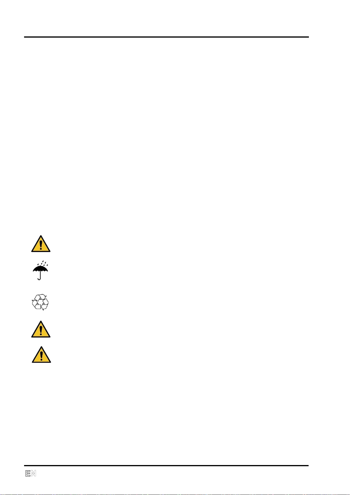
WARNING NOTICES AND SYMBOLS
Attention, see instructions for use
Caution, risk of electric shock
Consult instructions for use
CE mark of compliance
Caution, hot surface
Handling mark on package – FRAGILE
Handling mark on package – THIS SIDE UP
Handling mark on package – KEEP DRY
Handling mark on package – TEMPERATURE LIMITATIONS
Handling mark on package – LIMITED STACKING
Mark on package – RECYCLABLE MATERIAL
Alternating current
Ground connection
Equipotentiality
Fuse
Condensate drain
The following symbols are used for important information in the Installation,
Operation and Maintenance Manual and on packaging and the product:
GENERAL INFORMATION
NP-DK50 DE-18_02-2019 7
GENERAL INFORMATION
USE
The equipment can be installed and operated only in a dry, ventilated and
dust-free area. Climatic conditions for operation - see Technical data.
The compressor must stand on a flat and stable base.
The compressor must not be exposed to rain. The equipment must not be
used in humid or wet environments. Never use the compressor in the
presence of flammable liquids or gases.
Before connecting the compressor to respiration equipment, make sure
that it meets the requirements of the respiration equipment. Refer to the
Technical data for this purpose.
Any use other than the compressor‘s intended use is not considered to be
safe. The manufacturer is not responsible for any damages that result if
the compressor is used for any other purpose. Risk is exclusively
assumed by the operator/user.
STORAGE AND TRANSPORT
The compressor is shipped from the factory in transport packaging with the
pump stabilized, protecting it from damage during transport.
For transport, always use the original packaging and secure the compressor
in the upright position.
Protect the compressor from humidity, contamination and extreme
temperatures during transport and storage. A compressor in its original
packaging should be stored in a warm, dry and dust-free area.
Keep the packaging material, if possible. If not, dispose of the packaging
material in an environmentally-friendly way. Cardboard can be recycled.
Before moving or transporting the compressor, the pressure in the air tank
and hoses must be released and any condensed water must be drained.
Secure the motor to prevent movement before shipping.
Prior to transport it is necessary to secure the motor inside the
compressor (Chapter 5).
8 NP-DK50 DE-18_02-2019

EQUIPMENT DESCRIPTION
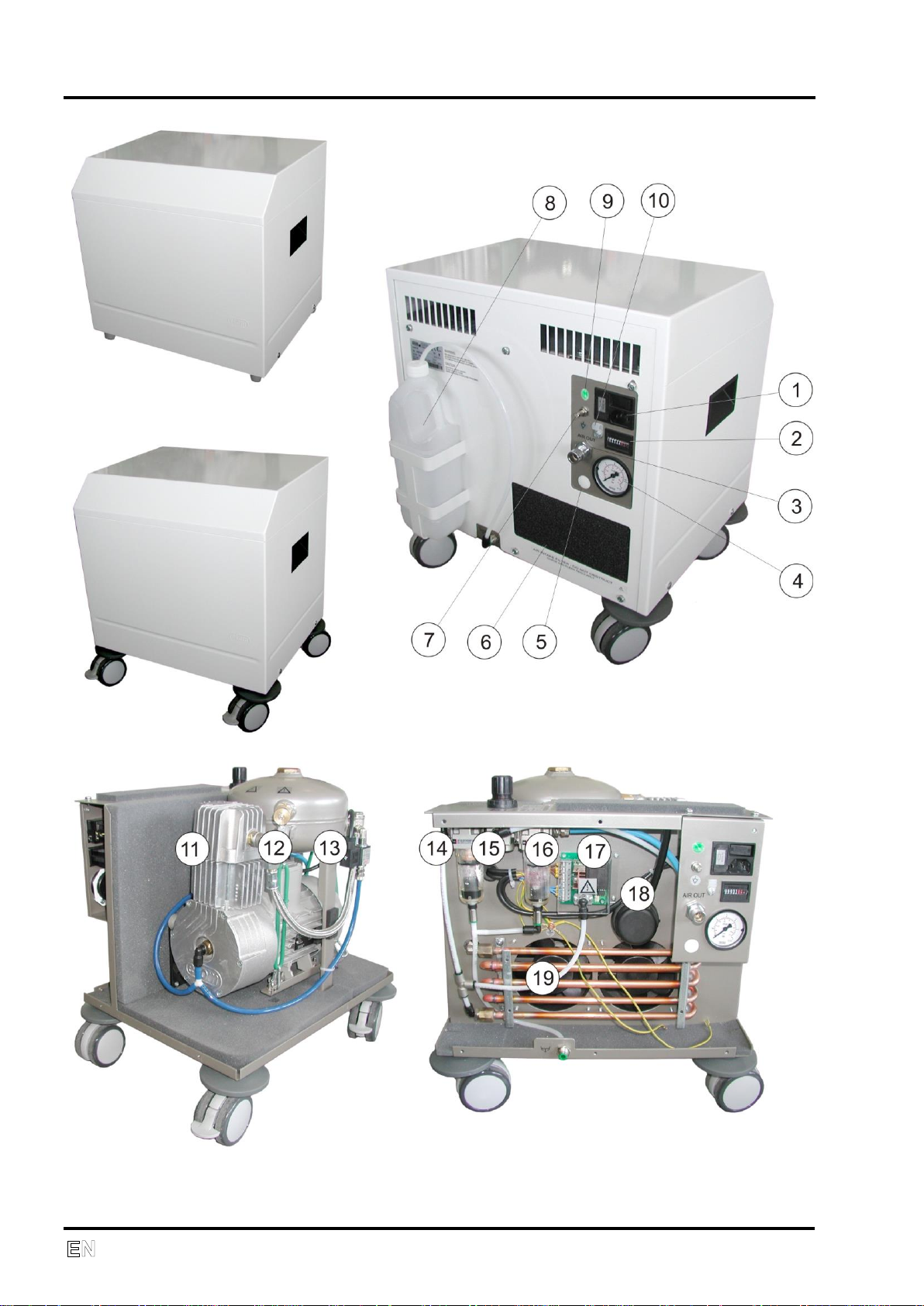
2. EQUIPMENT DESCRIPTION
1. Switch, main connector, fuses
2. Hour counter
3. OUT – compressed air output
4. Outlet pressure gauge (accuracy ± 5%)
5. WALL – input of compressed air from central distribution (Auxiliary
equipment)
6. Suction filter
7. Equipotential (ground) pin
8. Condensate tank
9. Power indicator
10. Socket for the electrical cord
11. Compressor
12. Safety valve
13. Air tank
14. Filter (40 μm) and water trap
15. Pressure regulator
16. Filter (5 μm) and water trap
17. Control electronics
18. Suction filter
19. Cooler
The compressor contains an oil-free piston (11) driven by a low-maintenance single-phase
electric motor. Compressed air is cooled in the cooler (19) where condensed water is
separated into a separate tank (8). Incoming air passes through two filters (6,18)
undergoing double filtration as it passes through the system (14,16). Constant pressure at
the output is maintained by the pressure regulator (15). The built-in air tank (13) enables
peak air consumption of 200 L/min.
The following applies to products with additional equipment – WALL coupling (5):
If the device is equipped with a WALL quick coupling (5), it can be used as a back-up air
source. In this configuration, the respiratory equipment is supplied with compressed air
from the central air distribution of the medical facility. Air pressure in the central distribution
line is sensed by a pressure sensor. If the pressure is sufficient, the compressor stays in
STANDBY mode. If the pressure falls, the control unit automatically places the compressor
into operation.
When the compressor is used as the main source of air, the control unit determines its
operation based on current demand for air. If air consumption is zero, the device switches
to STANDBY mode.
NP-DK50 DE-18_02-2019 9
EQUIPMENT DESCRIPTION
10 NP-DK50 DE-18_02-2019
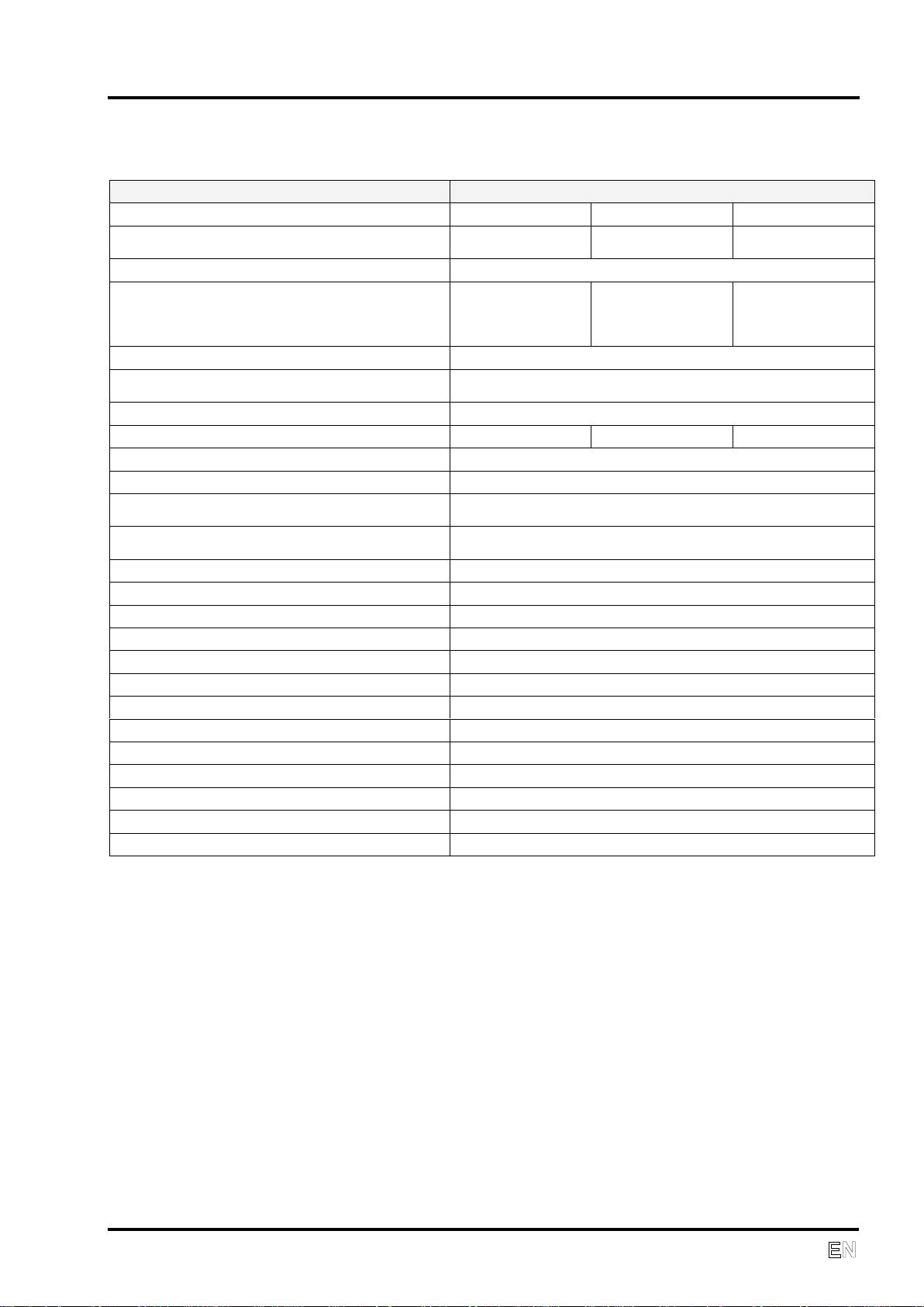
3. TECHNICAL DATA
TYPE
DK50 DE
VERSION basic
standard
advanced
Output flow at pressure
3.5 bar (51 psig)
L/min
40 / 32*
50 / 40*
60 / 50*
Peak flow
200** L/min ( 7 Cft/min )
Voltage / Frequency / Nominal current
V/Hz/A
230/50 / 2.8
230/60 / 2.8
120/60 / 5.6
100/50-60 / 5.6
230/50 / 2.8
230/60 / 2.8
120/60 / 5.6
100/50-60 / 5.6
230/50 / 3.3
230/60 / 3.9
120/60 / 6
100/50-60 / 6
Air filtration
m
5
Pressure dew point at 40 L/min
( 1.4 Cft/min ), 3 bar( 43.5 psig ), 20°C (68°F)
5°C (9°F) below the ambient temperature
Outlet connection DISS 1160-A (3/4"-16 UNF)
Sound level dB(A) @50Hz
≤49
≤50
≤51
Mode of operation
Continuous - S1
Separation of condensed water
Automatic
Output pressure
3.0 bar (43 psig)
Adjustable to max. 3.5 bar (51 psig)
Automatic start up pressure (backup***)
Decrease in pressure in the central distribution line under
2.8 bar ( 40.6 psig)
Air tank capacity
2 L (0.61gall UK)
Pressure range
5 bar ( 72.5 psig ) – 6.5 bar ( 94 psig)
Operating pressure of safety valve
7 bar ( 101.5 psig )
Adjustment of output air pressure
Pressure regulator
Dimensions of compressor
w x d x h
440 x 350 x 420 mm (17.5 x 14x 16.5 in )
Dimensions of compressor with wheels
w x d x h
470 x 380 x 505 mm (18.5 x 15x 20 in )
Dimensions of packaging
w x d x h
510 x 480 x 470 mm ( 20 x 19 x 18.5 in )
Net weight
34 kg ( 75 lbs )
Net weight of compressor with wheels
36 kg ( 79 lbs )
Gross weight
42 kg ( 93 lbs )
Gross weight of compressor with wheels
43 kg ( 95 lbs )
Implementation according to EN 60601-1, EN 12021
Class I.
Classification acc. to MDD 93/42 EEC, 2007/47 EC
II b
TECHNICAL DATA
* ) With membrane dryer (optional)
**) With 0.6 bar drop (8.7 psig)
***) Extra equipment
NP-DK50 DE-18_02-2019 11
TECHNICAL DATA
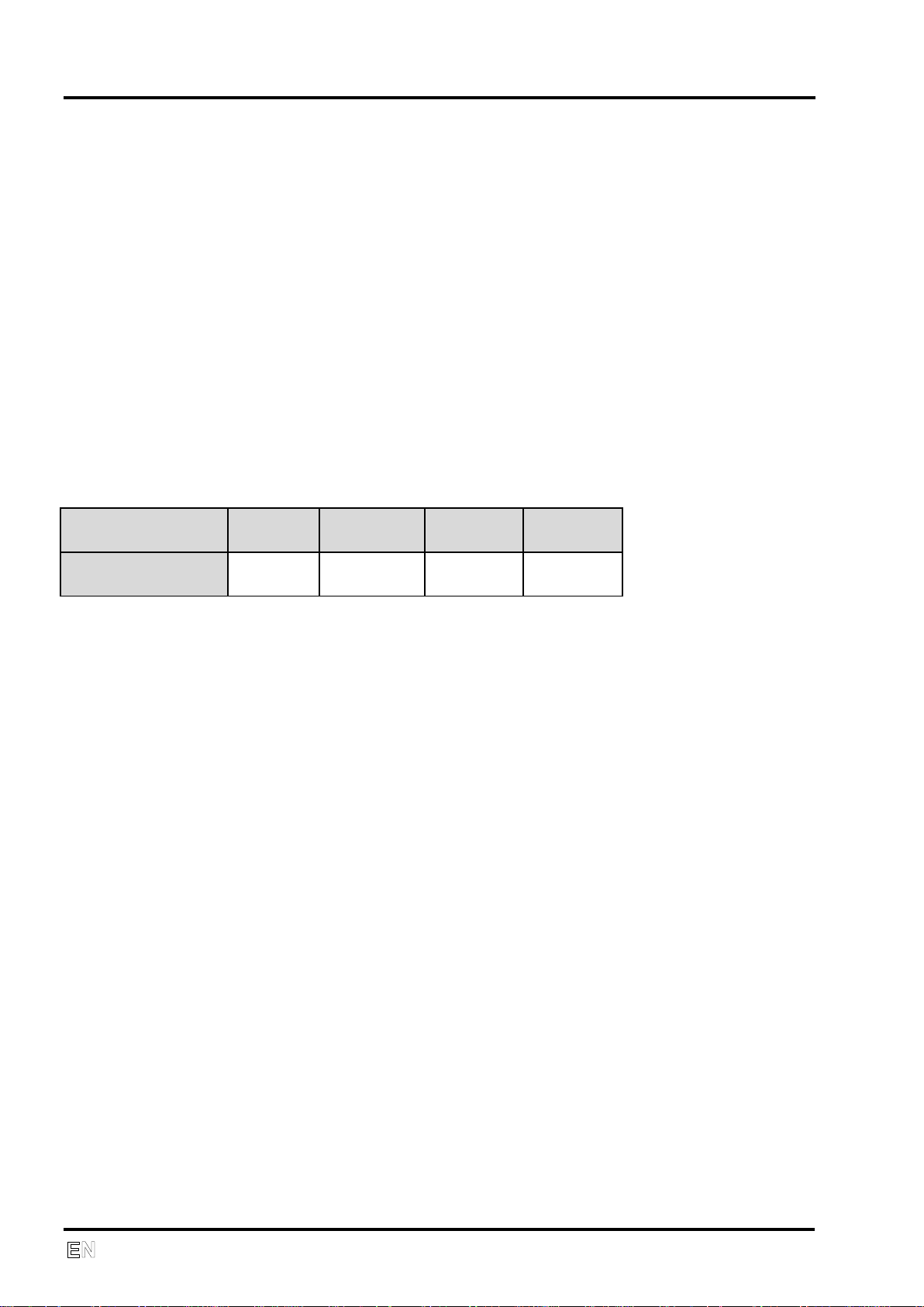
Elevation [mamsl]
0 - 1500
1501 -
2500
2501 -
3500
3501 -
4500
FAD [l/min]
FAD x 1
FAD x 0.8
FAD x
0.71
FAD x
0.60
Climatic conditions for storage and transport
Temperature –25°C to +55°C (-13°F to +131°F), 24 hrs +70°C (+158°F)
Relative air humidity 10% to 90% (no condensation)
Relative air humidity for seaworthy packing 10% to 100% (with condensation)
Climatic conditions for operation
Temperature +15°C to +40°C (+59°F to +104°F)
Relative air humidity up to +95%
IPX0 Rating
FAD efficiency correction for differences in elevation
FAD correction table
FAD efficiency refers to conditions at an elevation of 0 mamsl:
Temperature: 20°C
Atmospheric pressure: 101325 Pa
Relative humidity: 0%
12 NP-DK50 DE-18_02-2019
4. OPERATION
INSTALLATION AND FIRST OPERATION
Do not use the compressor immediately after unpacking as it will not
adjust to the ambient temperature.
Only qualified personnel can install the compressor and put it into
operation for the first time. The installer shall train the operating
personnel in the use and routine maintenance of the equipment.
Installation and training of personnel should be acknowledged by the
installer‘s signature on the installation certificate.
Prior to start-up, the four screws for transport stabilization must be
removed. If the compressor is switched on without removing the
stabilizers, the compressor could be permanently damaged.
The compressor does not contain a backup power supply.
Never block the suction filter on the backside or the vent outlets on the
top of the equipment.
If the compressor is equipped with a main source of air, the standby air
source must be available.
OPERATION
ANY MODIFICATION OF THIS EQUIPMENT IS FORBIDDEN!
If this equipment is used nearby other instruments, the equipment must
be observed in order to verify normal operations in the configuration it
will be used.
Instruments may be affected electro-magnetically!
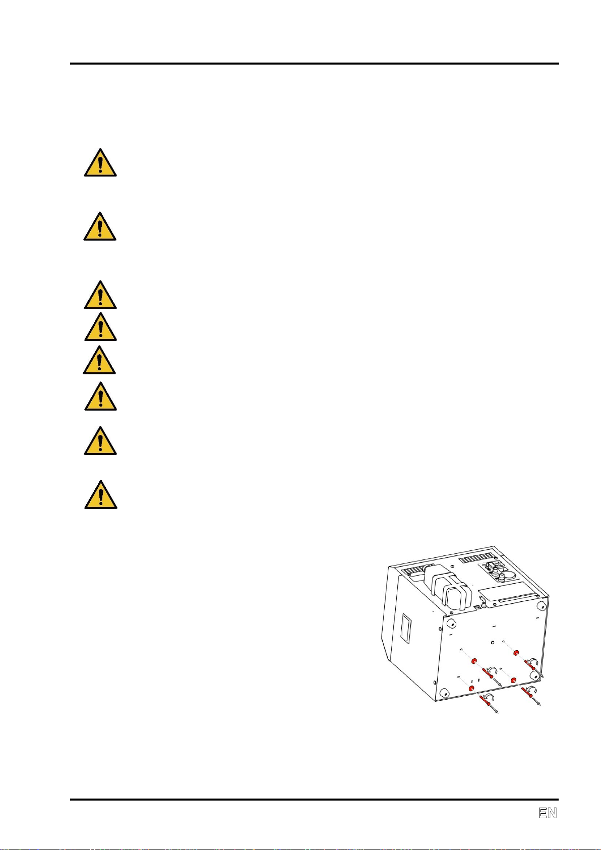
Removal of transport stabilizers
On the bottom of the unit are four M6
stabilizing screws that must be removed
before start-up. They are marked with a
red warning washer.
Please retain the stabilizing screws for
future transport of the compressor.
NP-DK50 DE-18_02-2019 13
OPERATION
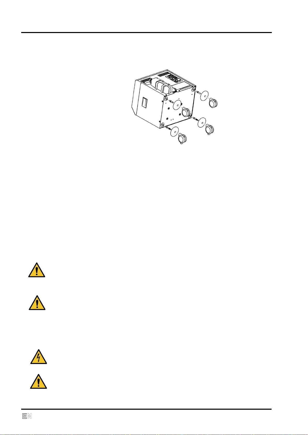
Wheel installation
Wheels must be installed following the figure below for versions of the
compressor with wheels.
Compressed air connection
The given appliance or respiratory apparatus should be connected to the
OUT (3) quick coupler, as this is the outlet for compressed air.
The following applies for equipment with additional equipment – WALL (5)
coupling:
Compressed air from the central distribution line is connected via the WALL
(5) quick coupling as this is the inlet for compressed air, if applicable. Air
from the distribution system is automatically connected through the
compressor to the OUT outlet port. In this configuration, the compressor
serves as a backup source of compressed air. If the air pressure from the
central distribution system is reduced, the compressor automatically switches
on and there is no interruption in the supply of continuously pressurized air at
the outlet of the compressor.
Please note that the air supply from the central distribution line
entering the compressor must be medical grade air (particulate size,
humidity.) The compressor does not modify the air from the central
distribution line.
The hose connecting the compressor to the respiration equipment
must not pass through a cold environment i.e. placed on the ground. It
should be as short as possible with no kinks (this may cause water to
condense inside the hose).
Electrical connection
The compressor comes with a plug containing an appropriate
protective contact (ground.) Adhere to local electrical regulations. The
voltage and frequency of the mains must comply with the
specifications on the data label.
The electrical cord must not be stressed or have any tension exerted
upon it, and must always be free.
14 NP-DK50 DE-18_02-2019

The socket must be accessible for safety reasons so that the equipment
The relevant current circuit must be protected.
Connection of the ground connection (7) to other equipment must adhere
Fasten the electrical cord through the holder (10).
First operation
Make sure that the stabilizing screws used during transport were
Check that the connection to the compressed air supply is correct.
Check for proper connection to the main power supply.
Switch on the pressure switch (1) to position “I”.
The compressor will be operational once it is put into operation. If there is no
air consumption at the output, the device switches to STANDBY mode. When
air consumption resumes, the compressor automatically switches on.
During operation, the device drains off the entrapped condensed water from
pneumatic circuits via automatic filter separators into a tank.
The following applies to device with additional equipment – WALL (5)
coupling:
After the compressor is put into operation, it shall work in one of the following
modes depending upon the pressure level in the central distribution and upon
air consumption.
STANDBY – When there is sufficient pressure in the central air distribution
line, the main switch is on, the compressor is idle. The device operates as a
standby source of air as it checks the pressure in the central air distribution
line and, if the pressure falls, the compressor switches on.
OPERATION
can be safely disconnected from the power supply in case of an
emergency.
to local electrical regulations.
removed.
When pressure is low in the central air distribution line, or if the device is
not connected to the central distribution line, the compressor is running. If
there is no air consumption at the outlet, the device switches to STANDBY
mode. When air consumption resumes, the compressor automatically
switches on.
During operation, the device drains the trapped condensed water from
pneumatic circuits via automatic filter separators into a separate tank.
NP-DK50 DE-18_02-2019 15
OPERATION
Accessories
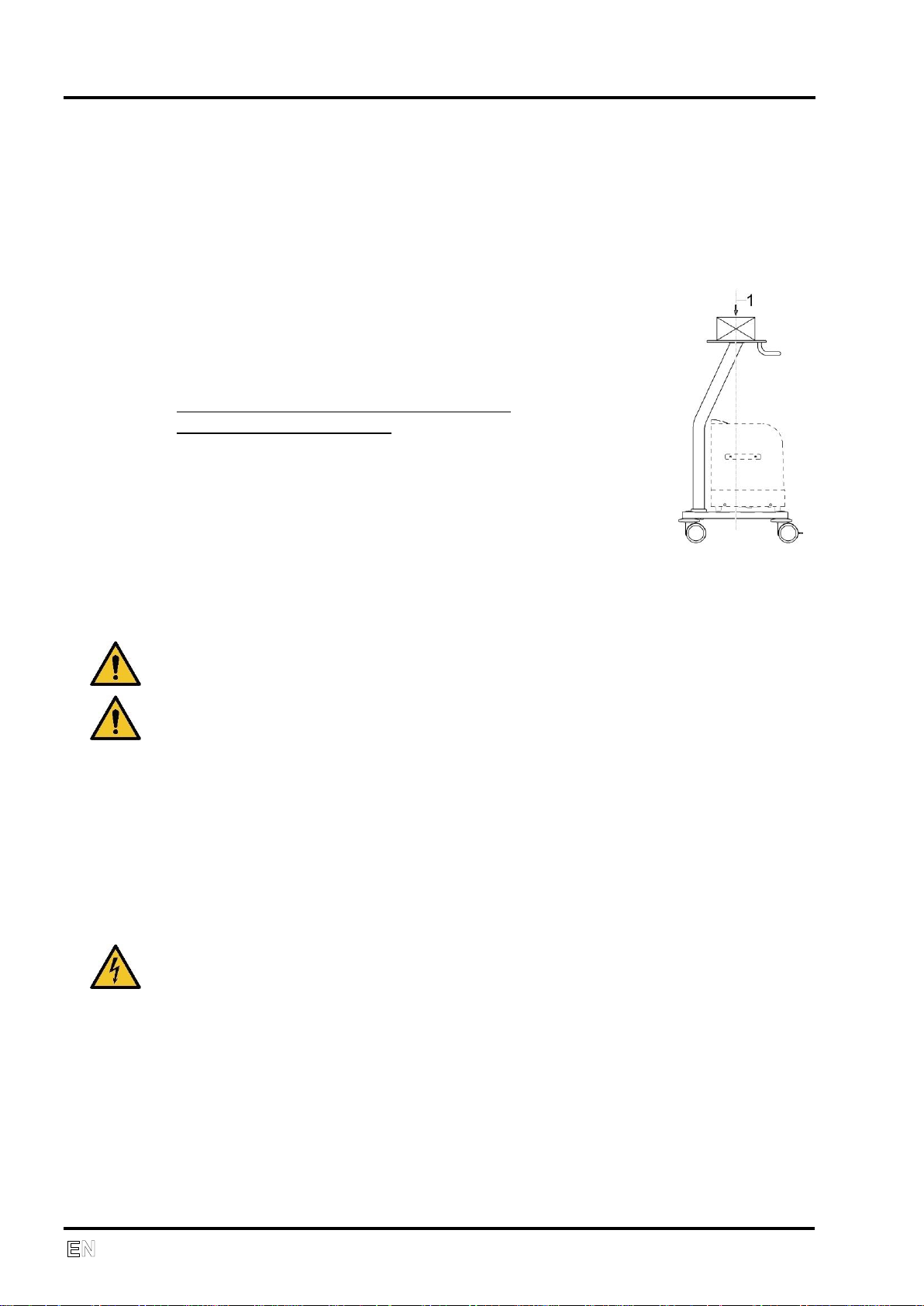
Trolley SD 30 (24)
The trolley accommodates the compressor, a fan and a humidifier. Large
casters allow for mobility and braking, guided by means of an ergonomic
handle. A wide base ensures the stability of the entire assembly.
Specifications
Supply No.: 602021222
Dimensions: 535x575x1070
Maximal load-carrying capacity with load
in the upper plate axis (1):
Trolley without compressor - 25kg
Trolley with compressor - 30kg
The manufacturer is not liable for any damage
resulting from excessive loads on the equipment!
The supplier is obliged to ensure the acceptability of a load delivered
by a supplied accessory.
It is forbidden to lean or press against an installed accessory for
support!
The equipment must be lifted when travelling over an obstacle!
Supporting equipment must be disassemble before transport!
The maximum load on the upper trolley plate is 30 kg!
Humidifier holder (25)
This clamp is used to attach the Fischer & Paykel humidifier to the trolley in
its proper position.
Supply No. 604031175
OPERATION
In case of emergency, switch the equipment off at the switch and pull
out the main power plug.
Switching the compressor on
The compressor is switched on at the main power switch (1) by putting it in
position "I".
16 NP-DK50 DE-18_02-2019
Running the compressor
Compressor operation is automatic. The compressor runs permanently,
when air consumption is lower than the set point; once set point is reached
the operation is switched to idle run. The pressure gauge displays the value
of output pressure. When air consumption stops, the compressor shall switch
off after around 30 seconds and switch on after air consumption is restored.
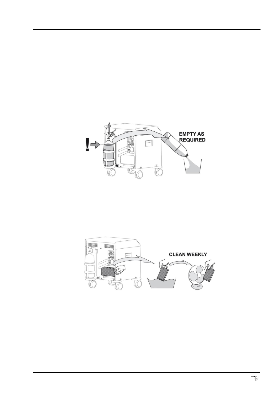
The condensed liquid drains into a tank (8) at the back of the device. When
the tank fills up, it must be emptied.
OPERATION
Cleaning and replacing filters
At least once a week take out and clean the suction filter (6) located on the
back side. Wash the filter in warm soapy water, rinse thoroughly and allow it
to dry. Insert the clean filters so that the intake openings are completely
covered by the filters. A replacement suction filter (6) No. 025000018 is
included in the basic equipment for the product.
Cleaning the compressor
To clean the compressor, use a detergent that contains no abrasives,
chemical solvents or other corrosive agents.
NP-DK50 DE-18_02-2019 17
MAINTENANCE
Maintenance
Page
Time interval
To be
performed by
Clean suction filter
13
At least once a
week
Staff
Safety valve check
15
Once per year
Qualified expert
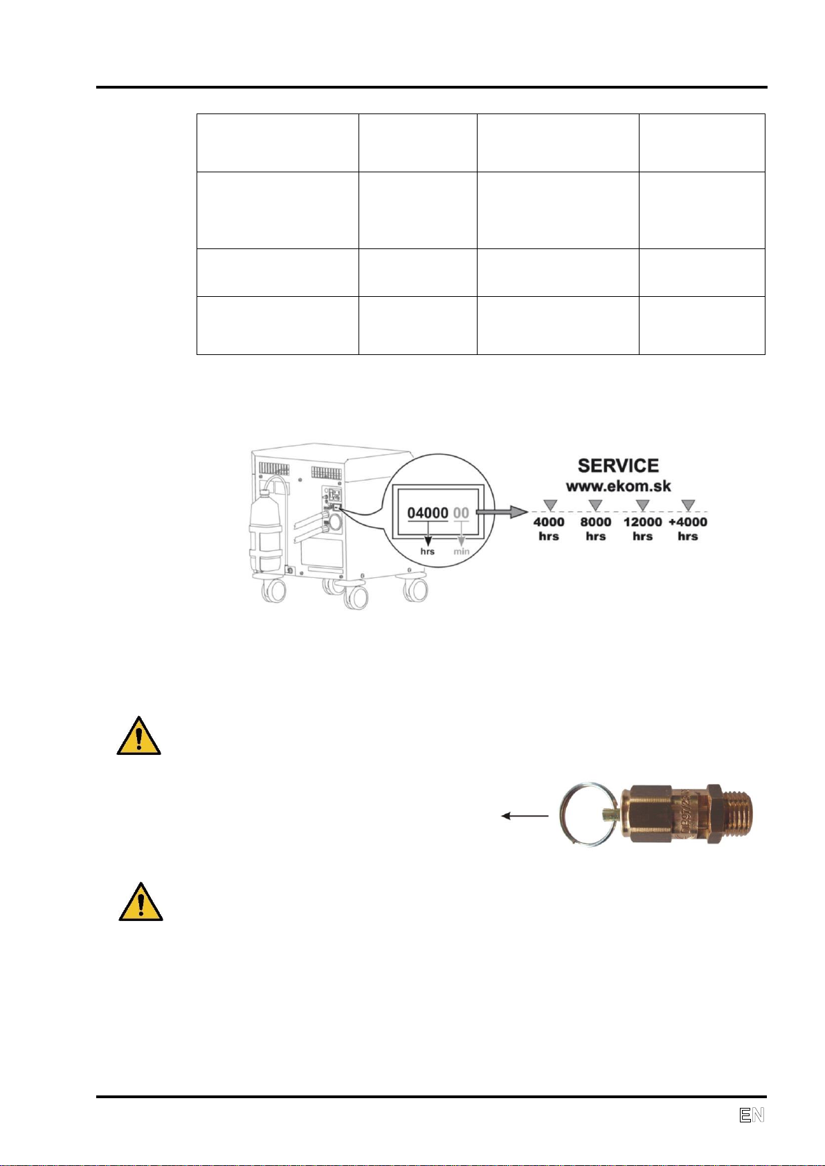
Replace filters in
filter
16
Every 4000 hours
Qualified expert
5. MAINTENANCE
REPAIRS AND SERVICE
Warranty and extended warranty repairs are to be completed by the
manufacturer or a service provider authorized by the manufacturer.
The manufacturer reserves the right to modify the equipment in any
way that will not alter the function or the operation of the equipment.
Only a qualified technician or the Customer Service Department of the
manufacturer may perform repairs that go beyond routine maintenance.
Use only spare parts and accessories approved by the manufacturer.
Prior to any maintenance or repairs, switch off the compressor and
disconnect it from the mains (pull out the main power plug).
Cover removal
- Unscrew the 6 screws from the rear cover
- Disconnect the grounding wire
- Remove the rear cover
- Unscrew the 4 screws from the rear of the main cover
- Disconnect the grounding wire
- Remove the main cover
- Reassemble using the opposite order
MAINTENANCE SCHEDULE
Notice!
The operating entity is obliged to ensure that all tests of the equipment are carried
out repeatedly at least once within every 24 months (EN 62353) or in intervals as
specified by the applicable national legal regulations. A report must be prepared on
the results of the tests (e.g.: according to EN 62353, Annex G), including the
measurement methods used.
18 NP-DK50 DE-18_02-2019
MAINTENANCE
Test the tightness of
joints and inspect
the equipment
16
After two years
Qualified expert
Replace piston
complete with piston
rings, O-rings and
bearing
Service
documentation
Every 8000 hours
Qualified expert
Replace suction
filter
16
Every 8000 hours
Qualified expert
Perform “Repeated
Test” according to
EN 62353
14
1 x 2 years
Qualified expert
Safety valve check
The safety valve is adjusted to 7 bar by the manufacturer, then tested
and marked. It must not be readjusted.
Only allow the safety valve freely
puff for a short period of time.
Never use the safety valve to release pressure in the air tank. This could
damage the safety valve.
NP-DK50 DE-18_02-2019 19
 Loading...