

EKOM DK50 9x4VRT/M, DK50 9x4VRTS/M User Manual
DK50-9x4VRT/M
EN
User manual

October 2018
Z_2195/2018
Chap. 3 – pgs.5
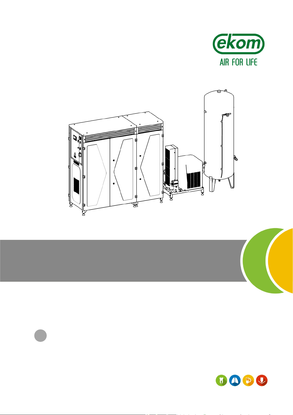
COMPRESSOR
DK50 9x4VRT/M
EKOM spol. s r. o.
Priemyselná 5031/18
SK-921 01 Piešťany
Slovak Republic
tel.: +421 33 7967255
fax: +421 33 7967223
www.ekom.sk
email: ekom@ekom.sk
DATE OF LAST REVISION
10/2018
NP-DK50-9x4VRTM_ED-EN-
2_10-2018
112000370-0001

DK50 9x4VRT/M
CONTENTS
IMPORTANT INFORMATION .......................................................................................................... 5
1. CONFORMITY WITH THE REQUIREMENTS OF EUROPEAN UNION DIRECTIVES ..................... 5
2. INTENDED USE .................................................................................................................................. 5
3. CONTRAINDICATIONS AND SIDE-EFFECTS ................................................................................... 5
4. WARNINGS AND SYMBOLS .............................................................................................................. 5
5. NOTICE ............................................................................................................................................... 6
6. STORAGE AND TRANSPORT ........................................................................................................... 7
7. TECHNICAL DATA .............................................................................................................................. 8
8. PRODUCT DESCRIPTION ............................................................................................................... 12
9. EQUIPMENT FUNCTION .................................................................................................................. 14
10. PNEUMATIC DIAGRAM .................................................................................................................... 16
INSTALLATION .............................................................................................................................. 17
11. CONDITIONS FOR USE ................................................................................................................... 17
12. PLACEMENT OF THE COMPRESSOR ........................................................................................... 18
13. PNEUMATIC CONNECTIONS .......................................................................................................... 20
14. ELECTRICAL CONNECTIONS ......................................................................................................... 21
OPERATION ................................................................................................................................... 25
15. INITIAL START UP OF THE DEVICE ............................................................................................... 2 5
16. SWITCHING THE COMPRESSOR ON ............................................................................................ 25
17. COMPRESSOR SHUT-DOWN ......................................................................................................... 3 0
MAINTENANCE ............................................................................................................................. 30
18. PRODUCT MAINTENANCE .............................................................................................................. 30
TROUBLESHOOTING AND REMEDYING PROBLEMS ............................................................... 39
19. TROUBLESHOOTING COMMON PROBLEMS ................................................................................ 39
20. REPAIR SERVICE ............................................................................................................................. 41
21. DISPOSAL OF THE DEVICE ............................................................................................................ 41
ANNEX ........................................................................................................................................... 42
22. MAPPING PARAMETERS ............................................................................................................... 42
23. INSTALLATION RECORD ................................................................................................................. 44
NP-DK50-9x4VRTM_ED-EN-2_10-2018 - 4 - 10/2018
DK50 9x4VRT/M
IMPORTANT INFORMATION
1. CONFORMITY WITH THE REQUIREMENTS OF EUROPEAN UNION DIRECTIVES
This product confirms to the requirements of Directives 93/42/EEC (Medical Device Directive) and
2006/42/EEC and is safe for the intended use when all safety instructions are followed.
2. INTENDED USE
The compressor is used as a central source of
clean, oil-free compressed air to power
individual devices and equipment with
compressed air used in large dental clinics
and laboratories, in hospitals wards and other
settings where the parameters and properties
of the compressed air are suitable to the
specific application.
3. CONTRAINDICATIONS AND SIDE-EFFECTS
There are no contraindications or side-effects known.
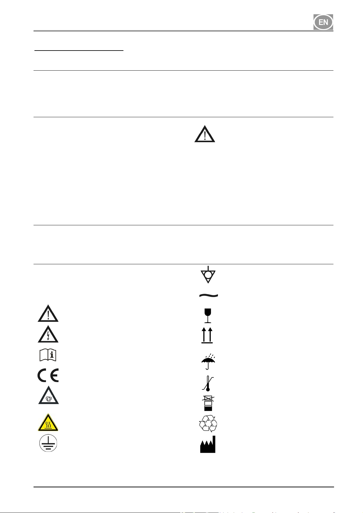
4. WARNINGS AND SYMBOLS
The following labels and symbols are used in
the Installation, Operation and Maintenance
Manual and on the equipment and its
packaging to indicate important details and
information:
Compressed air supplied by the
compressor is unsuitable for use
with artificial lung ventilation
devices without further filtration.
Any use of the product outside the framework
of its intended use is considered improper
use. The manufacturer is not liable for any
damages or injury resulting from misuse.
Terminal for ground connection
Alternating current
General warnings
Danger, electrocution hazard
Read the user manual
CE conformity marking
Handling mark on package –
FRAGILE
Handling mark on package – THIS
WAY UP
Handling mark on package – DO
NOT EXPOSE TO RAIN
Handling mark on package –
TEMPERATURE RANGE
Compressor is remote-controlled
and may start without warning
Warning! Hot surface
Earth (ground) connection
Handling mark on package –
LIMITED STACKING
Mark on package – RECYCLABLE
MATERIAL
Manufacturer
10/2018 NP-DK50-9x4VRTM_ED-EN-2_10-2018
- 5-

5. NOTICE
DK50 9x4VRT/M
The product is designed and manufactured to
be safe for the user and its surrounding
environment when used in the defined
manner. Keep the following warnings in mind.
This keeps risks to a minimum.
5.1. General warnings
READ THE USER MANUAL CAREFULLY
BEFORE USING THE DEVICE AND KEEP IT
FOR FUTURE USE!
The user manual aids in the correct
installation, operation and maintenance of
the product. It is included with the product
and must be kept close to it at all times.
Careful review of this manual will provide
the information necessary for the intended
use and correct operation of the product.
Equipment containing the condensing dryer
is provided with a separate manual for
these components.
The user manual corresponds to the
configuration of the product and its
compliance with applicable safety and
technical standards at the time of its
printing. The manufacturer reserves all
rights for the protection of its configuration,
methods and names.
Translation of the user manual is
performed in accordance with the best
available knowledge. The Slovak version is
to be used in the event of any
uncertainties.
5.2. General safety warnings
The manufacturer designed and manufactured
the product to minimise all risks when used
correctly for the intended purpose. The
manufacturer considers it responsible for
specifying the following general safety
precautions.
Only the original packaging ensures
optimal protection of the equipment during
transport. Save this packaging should you
ever have to return the equipment. The
manufacturer is not liable for damages
caused by faulty packaging when returning
a product for transport during the warranty
period.
Use a fork lift truck or similar hoisting
equipment for any movement or handling of
the product.
This warranty does not cover damages
originating from the use of accessories or
consumables other than those specified or
suggested by the manufacturer.
The manufacturer only guarantees the
safety, reliability and function of the
equipment if:
- installation, new settings, changes,
modifications and repairs are performed
by the manufacturer or its
representative, or a service provider
authorized by the manufacturer..
the product is used pursuant to the user
manual.
Use and operation of the product must
comply with all local codes and regulations.
The operator and user are responsible for
following all appropriate regulations in the
interests of performing work safely.
Only the use of original parts guarantees
the safety of operating personnel and
reliable operation of the product itself. Only
use accessories and parts mentioned in the
technical documentation or expressly
approved by the manufacturer.
The manufacturer assumes no liability for
any damages or other risks if any
accessories or parts other than mentioned
in the technical documentation or expressly
approved by the manufacturer are used.
This warranty does not cover damages
originating from the use of accessories or
consumables other than those specified or
suggested by the manufacturer.
The user must make sure that the
equipment is functioning correctly and
safely every time it is used.
The user / operator must be capable of
safely using and properly operating the
NP-DK50-9x4VRTM_ED-EN-2_10-2018 - 6 - 10/2018
DK50 9x4VRT/M
product. The user must be trained to
operate the product and must be
experienced.
Create operating regulations for the person
operating the product.
Wear hearing protection when starting the
product, during operation and any time it is
in operation.
Operating the product in operating
premises that may contain mixtures of
flammable gases such as operating rooms
or in areas that may contain explosive
mixtures of particulate, such as coal dust,
is prohibited.
Flammable materials pose an explosion
hazard!
Use of the product in wet or damp
environments is prohibited.
The user shall inform the supplier
immediately if any problem occurs in direct
connection with the operation of the
equipment.
5.3. Electrical system safety warnings
The equipment may only be connected to a
properly installed socket connected to earth
(grounded).
Before the product is plugged in, make
sure that the mains voltage and frequency
stated on the product are the same as the
power mains.
Check for possible damage to the product
and the connected air distribution system
before use. Replace damaged pneumatic
and electrical conductors immediately.
Immediately disconnect the product from
the mains in hazardous situations or when
a technical malfunction occurs.
During repairs and maintenance, ensure
that:
product is disconnected from the
mains
pressure is released from all lines
Only the manufacturer, or a qualified
specialist trained by the manufacturer may
install, modify or upgrade the product itself.
Only a qualified electrician may install
electrical components!
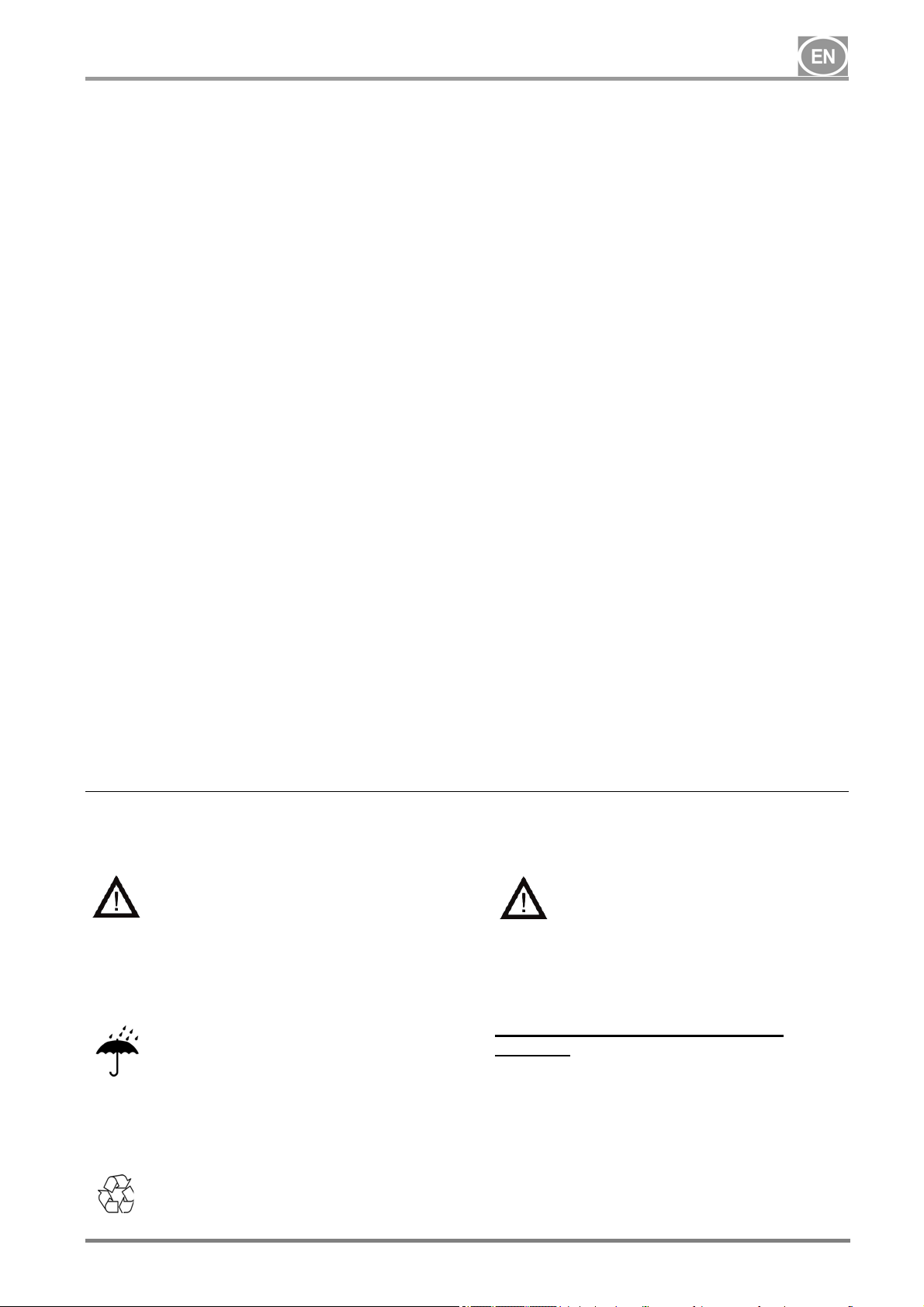
6. STORAGE AND TRANSPORT
The compressor is shipped from the factory in
a transport packaging. This protects the
device from damage during transport.
The original compressor
packaging must be used for
transport whenever possible. The
compressor is to be shipped in a
vertical position and must be
secured using transport straps.
Protect the compressor from humid
and dirty environments and extreme
temperatures during transport and
storage. Store a compressor in its
original packaging in a warm, dry and
dust-free area. Do not store near any
chemical substances.
Keep packaging material if possible.
If not, please dispose of the
packaging material in an
environmentally-friendly way.
Packaging cardboard can be
recycled with old paper.
The compressor must be
transported only when all air has
been vented. Before moving or
transporting the compressor,
release all the air pressure from
the tank and hoses and drain the
condensed water.
Ambient conditions for storage and
transport
Products may only be stored and transported
in vehicles that are free of any traces of
volatile chemicals under the following
conditions :
Temperature : +0°C až +50°C,
Max. relative humidity: 90%,
10/2018 NP-DK50-9x4VRTM_ED-EN-2_10-2018
- 7-
7. TECHNICAL DATA
DK50 9x4VRT/M
Compressors are designed for dry and wellventilated indoor environments with the
following conditions:
Tab.1
Type
Output at 6 bar
Voltage / frequency
Current draw (max.)
Main circuit breaker
Main feeder gauge
Enclosure
Air tank capacity
Working pressure
Safety valve
Noise level
l/min 2380 2380
V / Hz
A 45 45
A
2
mm
l 500 500
bar
bar 10 10
dB 85 74
DK50 9x4VRT/M DK50 9x4VRTS/M
Temperature : +5°C to +40°C,
Max. relative humidity.: 70%,
Max. absolute humidity.: 15 g/m
3 x 400 / 50 3 x 400 / 50
50 50
10 10
IP10 IP30
6 8 6 8
3
.
Total weight of compressor (net)
Weight - compressor module
Weight - dryer module
Weight of air tank
Compressor dimensions, total
(w x d x h)
Dimensions - compressor module
(w x d x h)
Dimensions – ED108 dryer
module
(w x d x h)
Air tank dimensions
(w x d x h)
Operating mode
Dryer performance with
condensation dryer (ED108)
(PDP*)
Time to fill air tank from 0 to 7 bar
Recommended cooling air
changes in space
Electrical class
kg 747 817
kg 540 610
kg 80 80
kg 127 127
mm 3800x705 x2100 3800x705 x2100
mm 1840x630 x1730 1860x705 x1760
mm 760x580x1050 760x580x1050
mm 770x705 x2100 770x705 x2100
+3°C +3°C
s 50 50
3
m
/h 3250 3250
class I.
S1 – 100% S1 – 100%
class I.
NP-DK50-9x4VRTM_ED-EN-2_10-2018 - 8 - 10/2018
DK50 9x4VRT/M
Tab.2
Type
DK50 9x4VRT/M DK50 9x4VRTS/M
Output at 8 bar
Voltage / frequency
Current draw (max.)
Main circuit breaker
Main feeder gauge
Enclosure
Air tank capacity
Working pressure
Safety valve
Noise level
Total weight of compressor (net)
Weight - compressor module
Weight - dryer module
Weight of air tank
Compressor dimensions, total
(w x d x h)
Dimensions - compressor module
(w x d x h)
Dimensions – ED108 dryer
module
(w x d x h)
Air tank dimensions
(w x d x h)
Operating mode
l/min 1780 1780
V / Hz
A 47 47
A
2
mm
l 500 500
bar
bar 11 11
dB 80 69
kg 747 817
kg 540 610
kg 85 74
kg 127 127
mm 3800x705 x2100 3800x705 x2100
mm 1840x630 x1730 1860x705 x1760
mm 760x580x1050 760x580x1050
mm 770x705 x2100 770x705 x2100
3 x 400 / 50 3 x 400 / 50
50 50
10 10
IP10 IP30
8 10 8 10
S1 – 100% S1 – 100%
Dryer performance with
condensation dryer (ED108)
(PDP*)
Time to fill air tank from 0 to 7 bar
Recommended cooling air
changes in space
Electrical class
+3°C +3°C
s 50 50
3
m
/h 3250 3250
class I.
class I.
(*) Apply the correction factor for the ED180 dryer
10/2018 NP-DK50-9x4VRTM_ED-EN-2_10-2018
- 9-
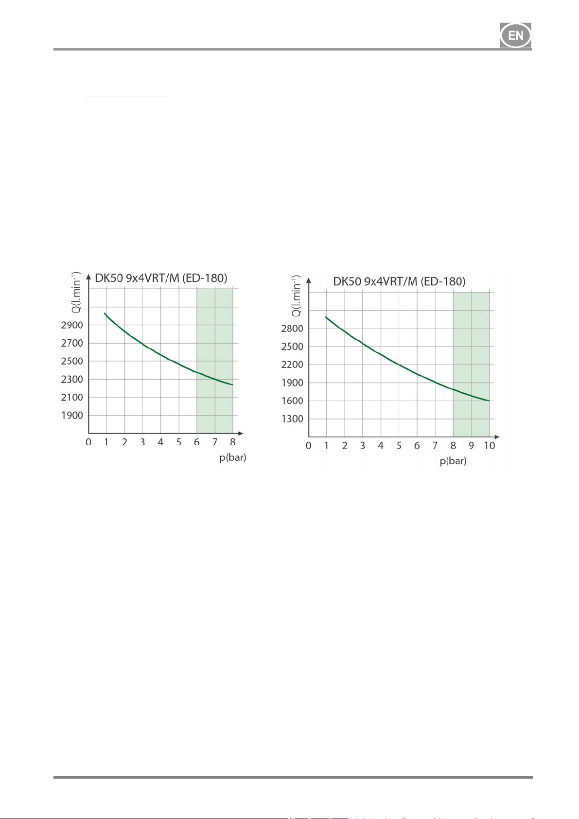
7.1. Free air delivery (FAD) correction due to elevation
FAD correction table
DK50 9x4VRT/M
Elevation [MASL]
FAD [l/min] FAD x 1 FAD x 0.8 FAD x 0.71 FAD x 0.60
0 - 1500 1501 - 2500 2501 - 3500 3501 - 4500
FAD reference conditions:
Elevation: 0 MASL
Temperature: 20°C
Atmospheric pressure: 101 325 Pa
Relative humidity: 0%
7.2. Dryer performance correction
ED180 dryer reference values
Temperature of air entering the dryer t
°C 35 (max.55)
inlet
Ambient temperature t0 °C 25 (max.45)
Working pressure p bar 7 (max.16)
Pressure dew point PDP °C +3 (-22 atm.)
ED180 dryer correction factors
Correction factor for working pressure
p (bar) 4 5 6 7 8 9 10
FC1
Correction factor for temperature of compressed air entering the dryer
t
(°C) 30 35 40 45 50 55
inlet
FC2
The cooler cools the compressed air to a temperature of ~19
temperature. Therefore:
t
= to + 19oC
inlet
It means E.G. at ambient temperature of t
Dew point correction factor
PDP (°C) 3 4 5 6 7 8 9
FC3
Correction factor for ambient temperature
to (°C) 25 30 35 40
FC4
0.78 0.85 0.93 1.0 1.06 1.11 1.15
1.2 1.0 0.85 0.71 0.58 0.49
o
C higher than the ambient
= 16oC, t
o
= 16o + 19o = 35oC → FC2 = 1,0
inlet
1 1.04 1.09 1.14 1.18 1.25 1.3
1 0.96 0.92 0.88
NP-DK50-9x4VRTM_ED-EN-2_10-2018 - 10 - 10/2018
DK50 9x4VRT/M
Calculation to determine dryer pressure dew point value:
Q
F
3
C
skut
FFFQ
421
CCCn
= actual airflow
Q
skut
Q
= nominal dryer flow (1800lit/min)
n
F
= working pressure correction factor
C1
F
= correction factor for air entering the dryer
C2
F
= dew point correction factor
C3
= ambient temperature correction factor
F
C4
See the user manual for the dryer on the CD for more information
10/2018 NP-DK50-9x4VRTM_ED-EN-2_10-2018
- 11-
8. PRODUCT DESCRIPTION
DK50 9x4VRT/M
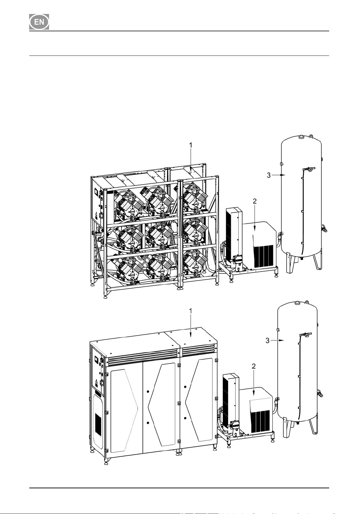
8.1. Variants
DK50 9x4VRT/M compressor comprised of
the following modules (Fig.1a):
- compressor module with 9 compressor
air pumps and controls
- a (condensing) dryer module with
connection hoses
- air tank module
Fig. 1a Compressor without enclosure
Fig.1b Compressor with enclosure
DK50 9x4VRTS/M compressor comprised of
the following modules (Fig. 1b):
- a compressor module with 9 compressor
air pumps and controls along with a
soundproof enclosure
- a (condensing) dryer module with
connection hoses
- air tank module
1. Compressor module
2. Dryer module
3. Air tank module
NP-DK50-9x4VRTM_ED-EN-2_10-2018 - 12 - 10/2018

DK50 9x4VRT/M
8.2. Accessories
Accessories are available for compressor
directly from the manufacturer (by special
request in an order) or may be ordered
directly from the manufacturer at a later time,
see below. Individual accessories may be
combined.
Accessories not included in the standard
order must be ordered separately!
8.2.1. Central air pump intake kit
This kit provides a properly sized central filter
located on the compressor module with intake
ducts to the individual compressors. This
extends the central filter replacement interval
(now every 2,000 hours) and eliminates the
need to replace filters on individual
compressors with simple and fast replacement
of the central filter.
Compressor type Kit article no.
DK50 9x4VRT/M 447000001-067
DK50 9x4VRTS/M 447000001-066
8.2.2. Set of compressed air outlet filters
The compressor may be equipped with a set
of filters if needed. A pressure regulator may
be added to the set of filters. The set of filters
is fully compatible with all compressors listed
above.
If a higher level of air filtration is
required, this specification must be
agreed upon with the supplier and
made clear in the order.
Level of filtration Pressure regulator Kit article no.
3µm
3µm – 0.3µm 447000001-060
SET OF
FILTERS
8.2.3. Compressor module enclosure (soundproofing)
Enclosing the compressor module reduces the
noise generated by the compressor by up to
11 dB(a) compared to the existing module
3µm – 0.01µm 447000001-062
1µm – AC/HC 447000001-064
3µm – 0.3µm
3µm – 0.01µm 447000001-063
1µm – AC/HC 447000001-065
Compressor type With central intake Kit article no.
DK50 9x4VRT/M yes 447000001-068
yes
no
while ensuring sufficient cooling for the air
pumps themselves for S1 class continuous
operations.
447000001-058
447000001-061
DK50 9x4VRT/M no 447000001-069
10/2018 NP-DK50-9x4VRTM_ED-EN-2_10-2018
- 13-
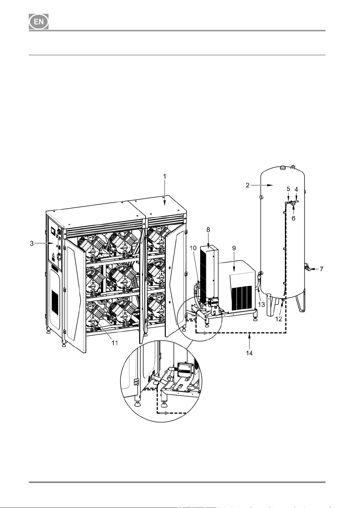
9. EQUIPMENT FUNCTION
DK50 9x4VRT/M
The compressor produces oil-free, dry,
filtered compressed air to power pneumatic
devices and equipment used in dental clinics
and laboratories, hospital departments and
more.
Compressor air pumps (11) draw in
atmospheric air through the inlet filters and
compress it through check valves and into the
compressed air system. From there, the
compressed air proceeds to the cooler (8), in
which the compressed air is cooled for the first
time and condensate is produced. The air
then passes through a water separator and
Fig. 2 Equipment function
into the condensing dryer (9). This continues
to lower the temperature of the air and
produces more condensate. The temperature
then rises to reduce the relative humidity. The
clean, dry air then passes through a check
valve and enters the air tank (2). Condensate
from the water separator and the dryer is
drained off into a 10 l vessel in the
condensate drain kit. The dryer ensures the
continuous and no-loss drying of the
compressed air. The treated compressed air
is then ready for additional use in the air tank.
1. Compressor module
2. Air tank
3. Switchboard
4. Safety valve
5. Pressure sensor
6. Pressure gauge
7. Outlet valve
8. Cooler
9. Condensation dryer
10. Water separator
11. Compressor air pump
12. Drain valve
13. Connecting hoses
14. Electric cables
NP-DK50-9x4VRTM_ED-EN-2_10-2018 - 14 - 10/2018
 Loading...