

EKOM DK50 4x4VRT/M, DK50 6x4VRT/M User Manual
DK50 4x4VRT/M
DK50 6x4VRT/M
User manual
EN

COMPRESSOR
DK50 4x4VRT/M
DK50 6x4VRT/M
EKOM spol. s r. o.
Priemyselná 5031/18
SK-921 01 Piešťany
Slovak Republic
tel.: +421 33 7967255
fax: +421 33 7967223
www.ekom.sk
email: ekom@ekom.sk
DATE OF LAST REVISION
03/2019
NP-DK50-Nx4VRTM_ED-EN-
4_03-2019
112000285-0001

DK50 4x4VRT/M
DK50 6x4VRT/M
03/2019 -4- NP-DK50-Nx4VRTM_ED-EN-4_03-2019
CONTENTS
IMPORTANT INFORMATION ........................................................................................................ 5
1. CE MARKING .......................................................................................................................................... 5
2. INTENDED USE ...................................................................................................................................... 5
3. CONTRAINDICATIONS AND SIDE-EFFECTS ...................................................................................... 5
4. WARNINGS AND SYMBOLS .................................................................................................................. 5
5. WARNING ............................................................................................................................................... 6
6. STORAGE AND TRANSPORT CONDITIONS ....................................................................................... 7
7. TECHNICAL DATA .................................................................................................................................. 8
8. PRODUCT DESCRIPTION ................................................................................................................... 12
9. EQUIPMENT FUNCTION ...................................................................................................................... 15
10. PNEUMATIC SCHEMATIC ................................................................................................................... 17
11. CONDITIONS FOR USE ....................................................................................................................... 18
12. PLACEMENT OF THE CMPRESSOR .................................................................................................. 19
13. PNEUMATIC CONNECTIONS .............................................................................................................. 21
14. ELECTRICAL CONNECTIONS ............................................................................................................. 22
OPERATION ................................................................................................................................ 25
15. COMMISSIONING ................................................................................................................................. 25
16. SWITCHING THE COMPRESSOR ON ................................................................................................ 26
17. SWITCHING OFF THE COMPRESSOR............................................................................................... 31
MAINTENANCE ........................................................................................................................... 31
18. EQUIPMENT MAINTENANCE .............................................................................................................. 31
TROUBLESHOOTING ................................ ................................................................ ................. 40
19. TROUBLESHOOTING COMMON PROBLEMS ................................................................................... 40
20. REPAIR SERVICE INFORMATION ...................................................................................................... 42
ANNEX ......................................................................................................................................... 43
21. MAPPING PARAMETERS .................................................................................................................... 43
22. INSTALLATION RECORD .................................................................................................................... 45
DK50 4x4VRT/M
DK50 6x4VRT/M
NP-DK50-Nx4VRTM_ED-EN-4_03-2019 03/2019
-5-
IMPORTANT INFORMATION
1. CE MARKING
Products marked with the CE mark of
compliance meet the safety guidelines of the
European Union (93/42/EEC).
2. INTENDED USE
The compressor is used as a source of clean,
oil-free compressed air to power dental unit,
instruments, and devices in laboratories
where the parameters and properties of the
compressed air are suitable for the specific
application.
Compressed air supplied by the
compressor is unsuitable for use
with artificial lung ventilation
devices without further filtration
Any other use of the product beyond its
intended use is considered an incorrect use.
The manufacturer is not liable for any
damages or injuries resulting from the
incorrect use.
3. CONTRAINDICATIONS AND SIDE-EFFECTS
There are no contraindications or side-effects known.
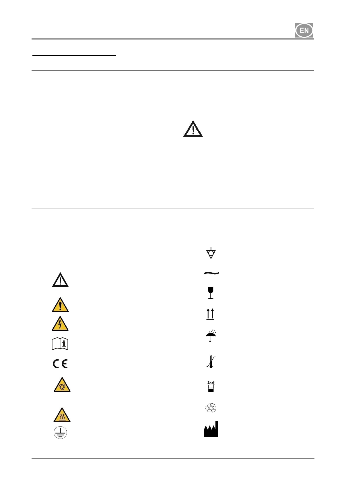
4. WARNINGS AND SYMBOLS
The following symbols are used in the user
manual, device and its packaging to denote
important details and information:
Information, instructions
and cautions to prevent
health and property
damages.
Warning
Danger, electric shock
hazard
Read the user manual
CE mark of compliance
The compressor is
remote-controlled and
may start without
warning.
Warning! Hot surface!
Earth (ground)
connection
Terminal for ground
connection
Alternating current
Handling mark on
package – FRAGILE
Handling mark on
package – THIS WAY
UP
Handling mark on
package – DO NOT
EXPOSE TO RAIN
Handling mark on
package –
TEMPERATURE
RANGE
Handling mark on
package – LIMITED
STACKING
Mark on package –
RECYCLABLE
MATERIAL
Manufacturer

DK50 4x4VRT/M
DK50 6x4VRT/M
03/2019 -6- NP-DK50-Nx4VRTM_ED-EN-4_03-2019
5. WARNING
The product has been designed and
manufactured to ensure it is safe for users
and its surroundings when used in the defined
manner. The following safety warnings must
be respected. This minimises any residual
risks.
5.1. General warnings
• The user manual serves to aid in the
proper installation, operation and
maintenance of the product. The user
manual is delivered with the equipment and
must be kept close to it at all times.
Following this manual precisely is the
prerequisite for the proper use of the
equipment in the defined manner.
• Equipment containing the condensing dryer
is provided with a separate manual for
these components.
• Only the original packaging ensures
protection of the equipment during
transport. Original packaging should be
kept if necessary to return the equipment
later. The manufacturer provides no
warranty for damages caused by faulty
packaging during the transport of
equipment returned during the warranty
period.
• Use a fork truck or other suitable type of
handling equipment to transport and move
the equipment
• The manufacturer only guarantees the
safety, reliability and function of the
equipment if:
- installation, new settings, changes,
modifications and repairs are performed by
the manufacturer or its representative, or a
service provider authorized by the
manufacturer.
- the equipment is used pursuant to the user
manual.
5.2. General safety warnings
• Operation of the equipment must be in
compliance with all local codes and
regulations. The operator and user are
responsible for following all appropriate
regulations in the interests of performing
work safely.
• Only the use of original parts can
guarantee the safety of operating
personnel and reliable operation of the
equipment. Only use accessories and parts
mentioned in the technical documentation
or expressly approved by the manufacturer.
• The manufacturer accepts no liability for
damages or related risks from the use of
any accessories or parts that are not
mentioned in the technical documentation
or expressly approved by the manufacturer.
The warranty does not cover damages
originating from the use of accessories or
consumable materials other than those
specified or recommended by the
manufacturer.
• The user must be convinced of the proper
function and safe condition of the
equipment before each and every use.
• The user/operator must be able to correctly
and safely operate the equipment. The
user must be trained to operate the
equipment and have the required level of
experience.
• Create operating instructions for personnel
operating the equipment
• Use hearing protection when starting up
the equipment, during operation and any
time it is running.
• Operation of the equipment in areas in
which flammable gas mixtures, such as
operating rooms, or in areas where
flammable mixtures of solids, such as coal
dust, may be present is prohibited.
• Flammable materials represent an
explosion hazard!
• Operating the equipment in damp or wet
areas is prohibited
• If any adverse effects or problems arise in
direct connection with the use of the
equipment, the user must inform their
supplier immediately.
DK50 4x4VRT/M
DK50 6x4VRT/M
NP-DK50-Nx4VRTM_ED-EN-4_03-2019 03/2019
-7-
5.3. Electrical system safety warnings
• The equipment must be connected to earth
(grounded).
• Check the mains voltage and frequency on
the equipment’s nameplate and ensure
they match the power system before
connecting the equipment to the mains.
• Inspect the equipment for any damage and
the connected air distribution system
before commissioning. Replace damaged
compressed air and electric lines
immediately.
• Immediately disconnect the equipment
from the mains if a technical failure or a
dangerous situation occurs.
• During repairs and maintenance, ensure
that:
- the equipment is disconnected from
the mains
- pressure is released from all lines
• The equipment must be installed or its
function expanded by the manufacturer or
a qualified professional trained by the
manufacturer.
• Only a qualified electrician may install
electrical components!
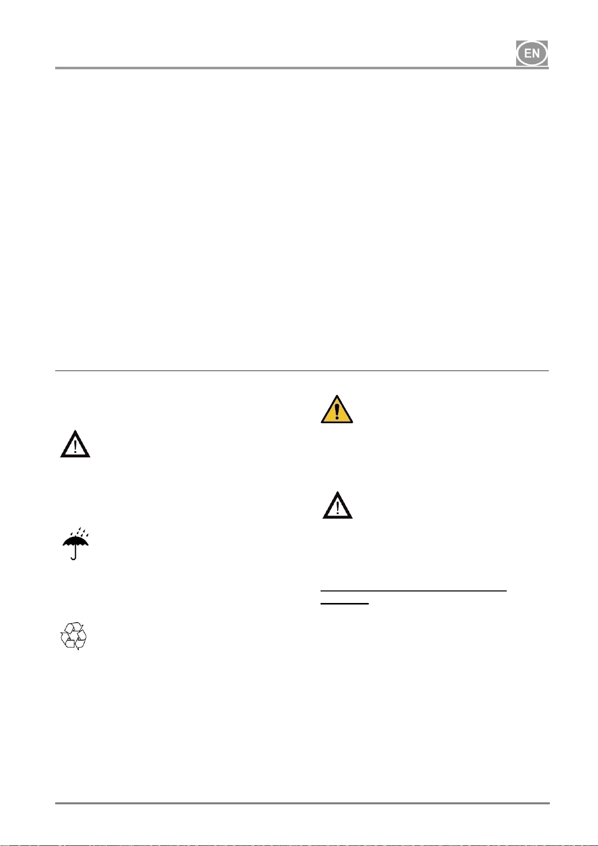
6. STORAGE AND TRANSPORT CONDITIONS
The compressor is shipped from the factory in
transport packaging. This protects the
equipment from damage during transport.
The original compressor
packaging must be used for
transport whenever possible. The
compressor is shipped in a
vertical position and must be
secured using transport straps.
Protect the compressor from humid
and dirty environments and extreme
temperatures during transport and
storage. A compressor in its original
packaging can be stored in a warm,
dry and dust-free area. Do not store
near any chemical substances.
Keep the packaging material if
possible. If not, please dispose of
the packaging material in an
environmentally friendly way and
recycle if possible. Packaging
cardboard can be recycled with
paper.
The compressor may only be
transported when all air pressure
has been vented. Before moving
or transporting the compressor,
release all air pressure from the
tank and hoses and drain
condensate from the air tank.
Storing or shipping the
equipment in any conditions
other than those specified below
is prohibited.
Ambient conditions for storage and
transport
The equipment may be stored in premises
and on vehicles without any traces of volatile
chemicals under the following conditions:
Temperature: +0°C to +50°C,
Max. relative humidity: 90%
DK50 4x4VRT/M
DK50 6x4VRT/M
03/2019 -8- NP-DK50-Nx4VRTM_ED-EN-4_03-2019
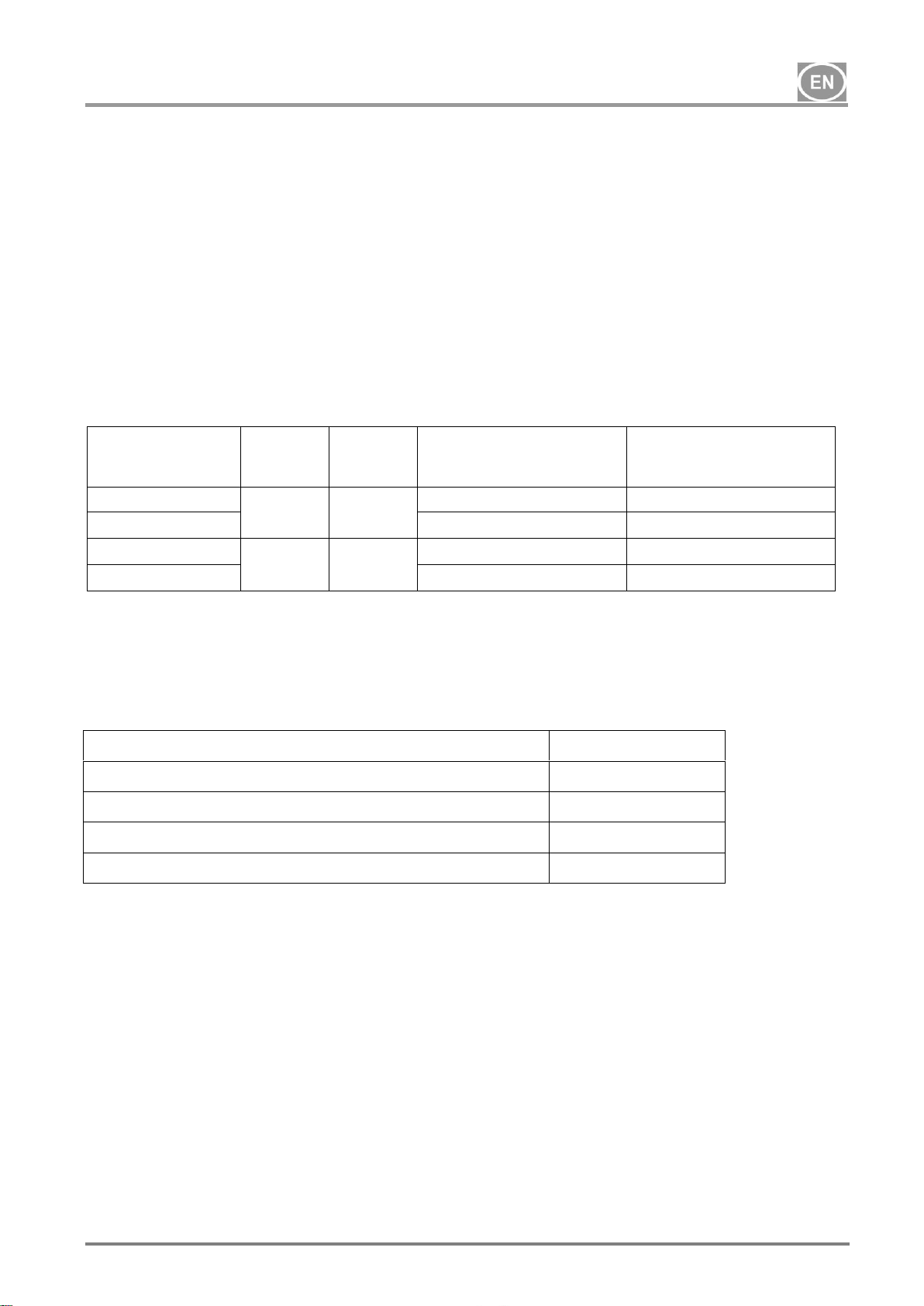
7. TECHNICAL DATA
Compressors are designed for dry and ventilated indoor environments with the following conditions:
Temperature: +5°C to +40°C,
Max. relative humidity: 70%,
Max. absolute humidity: 15 g/m3.
Tab. 1
Type
DK50
4x4VRT/M
DK50
4x4VRTS/M
DK50
6x4VRT/M
DK50
6x4VRTS/M
Output at 6 bar
l/min
1040
1040
1560
1560
Voltage / frequency
V / Hz
3 x 400 / 50
3 x 400 / 50
3 x 400 / 50
3 x 400 / 50
Current draw (max.)
A
22
22
31
31
Main circuit breaker
A
25
25
32
32
Main feeder gauge
mm2
4
4
6
6
Enclosure
IP10
IP30
IP10
IP30
Air tank capacity
l
500
500
500
500
Working pressure
bar
6 8
6 8
6 8
6 8
Safety valve
bar
10
10
10
10
Noise level
dB
80
69
83
72
Total weight of compressor (net)
kg
461
594
540
676
Weight - compressor module
kg
268
401
350
483
Weight - dryer module
kg
66
66
66
66
Weight of air tank
kg
127
127
127
127
Compressor dimensions, total
(w x d x h)
mm
3000x705
x2100
3000x705
x2100
3000x705
x2100
3000x705
x2100
Dimensions - compressor module
(w x d x h)
mm
1240x630
x1750
1250x705
x1790
1240x630
x1750
1250x705
x1790
Dimensions – ED108 dryer
module (w x d x h)
mm
760x550x1015
760x550 x1015
760x550 x1015
760x550 x1015
Air tank dimensions
(w x d x h)
mm
770x705 x2100
770x705 x2100
770x705 x2100
770x705 x2100
Operating mode
S1 – 100%
S1 – 100%
S1 – 100%
S1 – 100%
Dryer performance with
condensation dryer (ED108)
(PDP*)
+3°C
+3°C
+3°C
+3°C
Time to fill air tank from 0 to 7 bar
s
150
150
105
105
Recommended cooling air
changes in space
m3/h
2250
2250
3000
3000
Electrical class
class I.
class I.
class I.
class I.
DK50 4x4VRT/M
DK50 6x4VRT/M
NP-DK50-Nx4VRTM_ED-EN-4_03-2019 03/2019
-9-
Tab.2
Typ
DK50
4x4VRT/M
DK50
4x4VRTS/M
DK50
6x4VRT/M
DK50
6x4VRTS/M
Output at 8 bar
l/min
800
800
1315
1315
Voltage / frequency
V / Hz
3 x 400 / 50
3 x 400 / 50
3 x 400 / 50
3 x 400 / 50
current draw (max.)
A
23
23
33
33
Main circuit breaker
A
25
25
40
40
Main feeder gauge
mm2
4
4
6
6
Enclosure
IP10
IP30
IP10
IP30
Air tank capacity
l
500
500
500
500
Working pressure
bar
8 10
8 10
8 10
8 10
Safety valve
bar
11
11
11
11
Noise level
dB
80
69
83
72
Total weight of compressor (net)
kg
461
594
540
676
Weight - compressor module
kg
268
401
350
483
Weight - dryer module
kg
66
66
66
66
Weight of air tank
kg
127
127
127
127
Compressor dimensions, total
(w x d x h)
mm
3000x705
x2100
3000x705
x2100
3000x705
x2100
3000x705
x2100
Dimensions - compressor module
(w x d x h)
mm
1240x630
x1750
1250x705
x1790
1240x630
x1750
1250x705
x1790
Dimensions – ED108 dryer
module (w x d x h)
mm
760x550x1015
760x550 x1015
760x550 x1015
760x550 x1015
Air tank dimensions (w x d x h)
mm
770x705 x2100
770x705 x2100
770x705 x2100
770x705 x2100
Operating mode
S1 – 100%
S1 – 100%
S1 – 100%
S1 – 100%
Dryer performance with
condensation dryer (ED108)
(PDP*)
+3°C
+3°C
+3°C
+3°C
Time to fill air tank from 0 to 7 bar
s
170
170
115
115
Recommended cooling air
changes in space
m3/h
2250
2250
3000
3000
Electrical class
class I.
class I.
class I.
class I.
(*) Apply the correction factor for the ED108 dryer
DK50 4x4VRT/M
DK50 6x4VRT/M
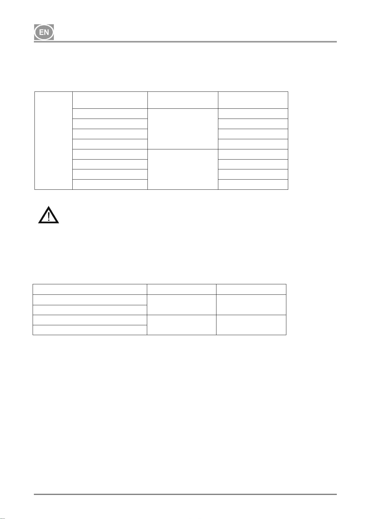
03/2019 -10- NP-DK50-Nx4VRTM_ED-EN-4_03-2019
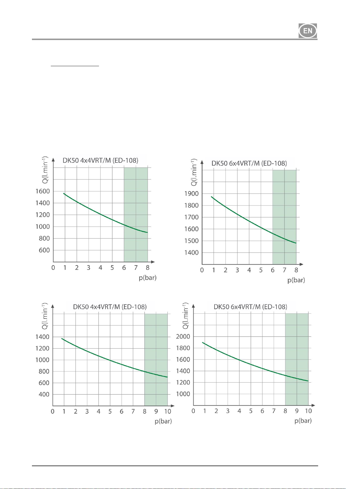
7.1. Free air delivery (FAD) correction due to elevation
FAD correction table
FAD output related to conditions:
Elevation: 0 MASL
Temperature: 20°C
Atmospheric pressure: 101325 Pa
Relative humidity: 0%
7.2. Dryer performance correction
ED108 dryer reference values
Temperature of air entering the dryer
t
inlet
°C
35 (max. 55)
Ambient temperature
t0
°C
25 (max. 45)
Working pressure
p
bar
7 (max. 16)
Pressure dew point
PDP
°C
+3 (-22 atm)
ED108 dryer correction factors
Correction factor for working pressure
p (bar) 4 5 6 7 8 9
10
FC1
0.78
0.85
0.93
1.0
1.06
1.11
1.15
Correction factor for temperature of compressed air entering the dryer
t
inlet
(°C)
30
35
40
45
50
55
FC2
1.2
1.0
0.85
0.71
0.58
0.49
The cooler cools the compressed air to a temperature of ~19oC higher than the ambient
temperature. Therefore:
t
inlet
= to + 19oC
It means E.G. at ambient temperature of to = 16oC, t
inlet
= 16o + 19o = 35
o
C → F
C2
= 1,0
Dew point correction factor
PDP (°C)
3 4 5 6 7 8 9
FC3 1 1.04
1.09
1.14
1.18
1.25
1.3
Correction factor for ambient temperature
to (°C)
25
30
35
40
FC4 1 0.96
0.92
0.88
Elevation [MASL]
0 - 1500
1501 - 2500
2501 - 3500
3501 - 4500
FAD [l/m]
FAD x 1
FAD x 0.8
FAD x 0.71
FAD x 0.60
DK50 4x4VRT/M
DK50 6x4VRT/M
NP-DK50-Nx4VRTM_ED-EN-4_03-2019 03/2019
-11-
Calculation to determine dryer pressure dew point value:
421
3
CCCn
skut
C
FFFQ
Q
F
Q
skut
= actual airflow
Qn = nominal dryer flow (1800 l/m)
FC1 = working pressure correction factor
FC2 = correction factor for air entering the dryer
FC3 = dew point correction factor
FC4 = ambient temperature correction factor
See the user manual for the dryer on the CD for more information
DK50 4x4VRT/M
DK50 6x4VRT/M
03/2019 -12- NP-DK50-Nx4VRTM_ED-EN-4_03-2019
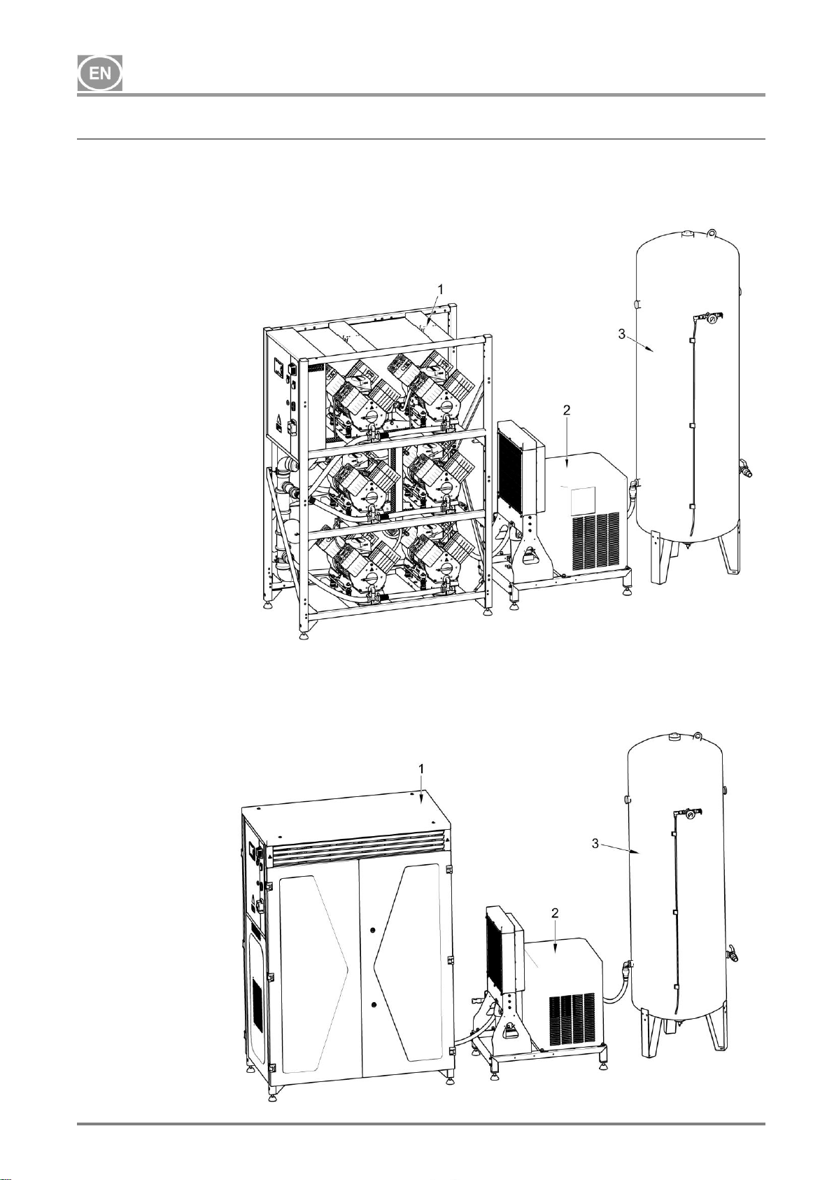
8. PRODUCT DESCRIPTION
8.1. Delivery includes
DK50 4x4VRT/M or DK50 6x4VRT/M
compressor comprised of the following
modules (Fig. 1a):
- compressor module with 4 or 6
compressor aggregates and controls
- a (condensing) dryer module with
connection hoses
- air tank module
Fig. 1a Compressor without enclosure
DK50 4x4VRTS/M or DK50 6x4VRTS/M
compressor comprised of the following
modules
(Fig. 1b):
- a compressor module with 4 or 6
compressor aggregates and controls
along with a soundproof enclosure
- a (condensing) dryer module with
connection hoses
- air tank module
Fig. 1b Compressor with enclosure
1. Compressor module
2. Dryer module
3. Air tank module
DK50 4x4VRT/M
DK50 6x4VRT/M
NP-DK50-Nx4VRTM_ED-EN-4_03-2019 03/2019
-13-
8.2. Accessories
Accessories are available for compressor
directly from the manufacturer (by special
request in an order) or may be ordered
directly from the manufacturer at a later time,
see below. Individual accessories may be
combined.
Accessories not included in the standard
order must be ordered separately!
8.2.1. DK50 4x4VRT/M performance
enhancement kit
If the performance of an existing DK50
4x4VRT compressor is insufficient, the
manufacturer has developed an accessory
DK50 6x4VRT/M performance enhancement
kit.
The DK50 4x4 VRT/M conversion kit converts
the existing compressor into a fully functional
DK50 6x4VRT/M compressor with the
required parameters in an efficient manner at
optimal cost.
Compressor type
Central
intake
Dryer
type
Rated voltage /
working pressure
Kit article no.
DK50 4x4VRT/M
no
ED-108
3x400V/50Hz (6-8bar)
447000001-024
DK50 4x4VRTS/M
3x400V/50Hz (8-10bar)
447000001-034
DK50 4x4VRT/M
yes
ED-108
3x400V/50Hz (6-8bar)
447000001-025
DK50 4x4VRTS/M
3x400V/50Hz (8-10bar)
447000001-035
8.2.2. Central aggregate intake kit
This kit provides a properly sized central filter
located on the compressor module with intake
ducts to the individual compressors. This
extends the central filter replacement interval
(now every 2,000 hours) and eliminates the
need to replace filters on individual
compressors with simple and fast replacement
of the central filter.
Compressor type
Kit article no.
DK50 4x4VRT/M
447000001-021
DK50 4x4VRTS/M
447000001-020
DK50 6x4VRT/M
447000001-019
DK50 6x4VRTS/M
447000001-018
DK50 4x4VRT/M
DK50 6x4VRT/M
03/2019 -14- NP-DK50-Nx4VRTM_ED-EN-4_03-2019
8.2.3. Set of compressed air outlet filters
The compressor may be equipped with a set
of filters if needed. A pressure regulator may
be added to the set of filters. The set of filters
is fully compatible with all compressors listed
above.
SET OF
FILTERS
Level of filtration
Pressure regulator
Kit article no.
3 µm
yes
447000001-010
3 µm - 0.3 µm
447000001-012
3 µm - 0.01 µm
447000001-014
1µm – AC/HC
447000001-016
3 µm
no
447000001-011
3 µm - 0.3 µm
447000001-013
3 µm - 0.01 µm
447000001-015
1µm – AC/HC
447000001-017
If a higher level of air filtration is
required, this specification must be
agreed upon with the supplier and
made clear in the order.
8.2.4. Compressor module enclosure
(soundproofing)
Enclosing the compressor module reduces the
noise generated by the compressor by up to
11 dB(a) compared to the existing module
while ensuring sufficient cooling for the
aggregates themselves for S1 class
continuous operations.
Compressor type
With central intake
Kit article no.
DK50 4x4VRT/M
yes
447000001-022
DK50 6x4VRT/M
DK50 4x4VRT/M
no
447000001-023
DK50 6x4VRT/M
DK50 4x4VRT/M
DK50 6x4VRT/M
NP-DK50-Nx4VRTM_ED-EN-4_03-2019 03/2019
-15-
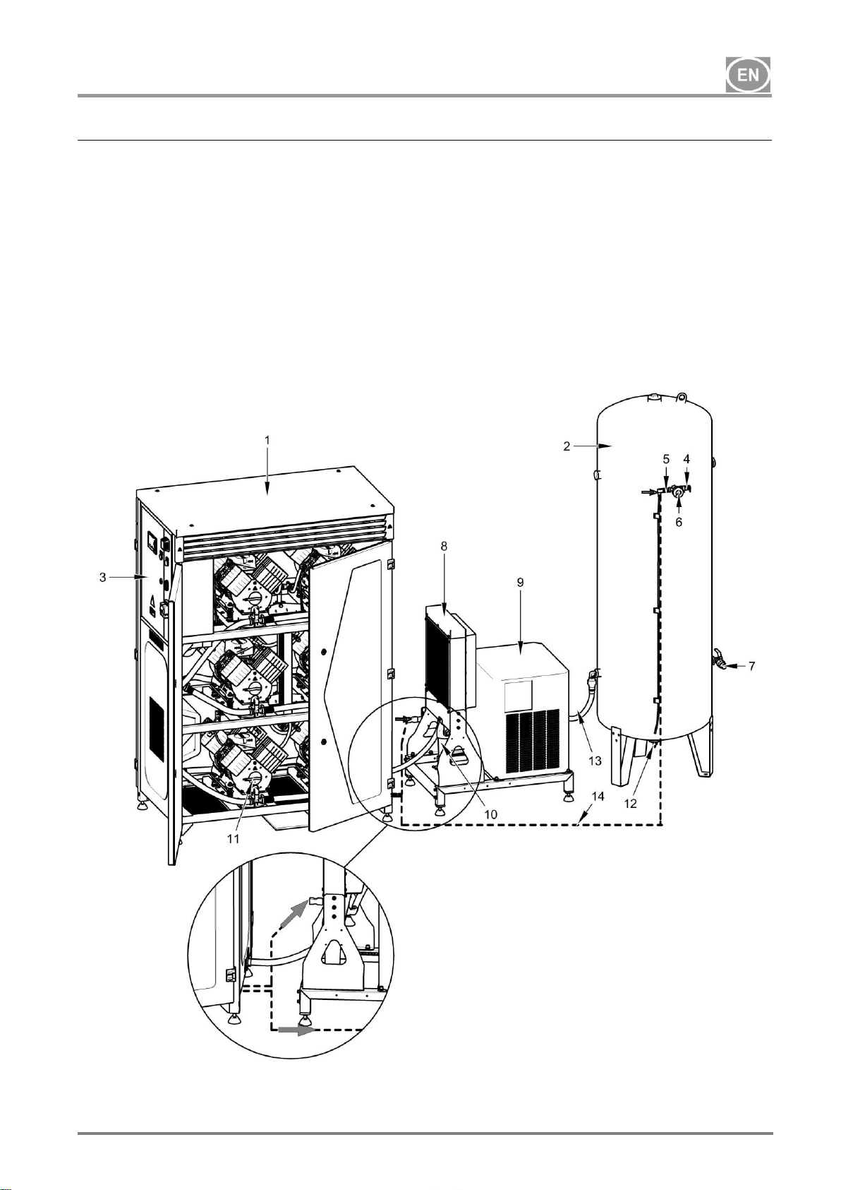
9. EQUIPMENT FUNCTION
The compressor produces oil-free, dry,
filtered compressed air to power pneumatic
devices and equipment used in dental clinics
and laboratories, hospital departments and
more.
Compressor air pumps (11) draw in
atmospheric air through the inlet filters and
compress it through check valves and into the
compressed air system. From there, the
compressed air proceeds to the cooler (8), in
which the compressed air is cooled for the first
time and condensate is produced. The air
then passes through a water separator and
into the condensing dryer (9). This continues
to lower the temperature of the air and
produces more condensate. The temperature
then rises to reduce the relative humidity. The
clean, dry air then passes through a check
valve and enters the air tank (2). Condensate
from the water separator and the dryer is
drained off into a 10 l vessel in the
condensate drain kit. The dryer ensures the
continuous and no-loss drying of the
compressed air. The treated compressed air
is then ready for additional use in the air tank.
Fig. 2 Equipment function
1. Compressor module
2. Air tank
3. Switchboard
4. Safety valve
5. Pressure sensor
6. Pressure gauge
7. Outlet valve
8. Cooler
9. Condensation dryer
10. Water separator
11. Compressor aggregate
12. Drain valve
13. Connecting hoses
14. Electric cables
 Loading...