

EKOM DK50 4VR/50, DK50 4VR/50S Installation, Operation And Maintenance Manual

DK50 4VR/50
CONTENTS
IMPORTANT INFORMATION ................................................................................................................. 3
1. CE MARKING ............................................................................................................................ 3
2. WARNINGS ................................................................................................................................ 3
3. ALERT NOTICES AND SYMBOLS ............................................................................................ 4
4. STORAGE AND TRANSPORT .................................................................................................. 4
5. TECHNICAL DATA ..................................................................................................................... 5
6. PRODUCT DESCRIPTION ........................................................................................................ 6
7. FUNCTION ................................................................................................................................. 8
INSTALLATION ..................................................................................................................................... 12
8. USE ........................................................................................................................................... 12
9. INSTALLATION ........................................................................................................................ 12
10.WIRING DIAGRAMS ................................................................................................................ 16
11.PNEUMATIC DIAGRAM ........................................................................................................... 18
12.FIRST OPERATION ................................................................................................................. 19
OPERATION .......................................................................................................................................... 20
13.SWITCHING THE COMPRESSOR ON ................................................................................... 20
MAINTENANCE .................................................................................................................................... 22
14.MAINTENANCE SCHEDULE ................................................................................................. 22
15.MAINTENANCE ........................................................................................................................ 22
16.STORAGE ................................................................................................................................ 25
17.DISPOSING OF THE APPLIANCE .......................................................................................... 25
18.REPAIR SERVICE .................................................................................................................... 25
19.SOLVING PROBLEMS ............................................................................................................. 2 5
NP-DK50 4VR50-11_04-2018 - 2 - 04/2018

DK50 4VR/50
IMPORTANT INFORMATION
1. CE MARKING
Products labeled with the CE mark of compliance meet the safety guidelines (93/42/EEC) of the European
Union.
2. WARNINGS
2.1. General warnings
This Installation, Operation and Maintenance Manual is a part of the appliance and must be kept with the
compressor. Careful review of this manual will provide the information necessary for correct operation of the
appliance.
The safety of operating personnel and trouble-free operation of the appliance are guaranteed only if
original parts are used. Only accessories and parts mentioned in the technical documentation or expressly
approved by the manufacturer can be used.
If any other accessories or consumable materials are used, the manufacturer cannot be held responsible
for the safe operation of the appliance. This guarantee does not cover damages originating from the use of
accessories or consumable material other than those specified or suggested by the manufacturer.
The manufacturer guarantees the safety, reliability and function of the appliance only if:
- Installation, new settings, amendments, extensions and repairs are performed by the manufacturer or
its representative, or a service provider authorized by the manufacturer
- The appliance is used in accordance with this Installation, Operation and Maintenance Manual
The manufacturer reserves all rights for the protection of its wiring diagrams, methods and names.
Translation of Manual for Installation, Operation and Maintenance is carried out in accordance with the
best knowledge. In the case of ambiguities, the Slovak version of the text prevails.
2.2. General safety warnings
The manufacturer developed and designed the equipment in such a way so that any risks were excluded if it
is used according to intention. The manufacturer considers it to be its obligation to describe the following
safety measures in order to exclude residual damages.
Operation of the appliance must be in compliance with all local codes and regulations.
Original packaging should be kept for the return of the appliance. Only the original packaging ensures
protection of the appliance during transport. If it is necessary to return the appliance during the guarantee
period, the manufacturer is not liable for damages caused by improper packaging.
Each time the appliance is used, the operator must make sure that it is functioning correctly and safely.
The user must fully understand the operation of the appliance.
The product is not intended for operation in areas with a risk of explosion.
If any problem occurs during use of the appliance, the user must inform his supplier immediately.
2.3. Electrical system safety warnings
The appliance must be connected to earth (grounded).
Before the appliance is plugged in, make sure that the mains voltage and mains frequency stated on the
appliance are the same as the power mains.
Prior to putting into operation it is necessary to check for possible damage of the equipment and
connected air and electric distributions. Damaged pneumatic and electric lines must be immediately
replaced.
Immediately disconnect the appliance from the mains (pull out mains plug) if a technical failure occurs.
During repairs and maintenance, ensure that:
- The mains plug is pulled out from the socket
- Pressure pipes are vented and pressure is released from the air tank.
The appliance must be installed by an approved, qualified technician.
04/2018 - 3 - NP-DK50 4VR50-11_04-2018
DK50 4VR/50
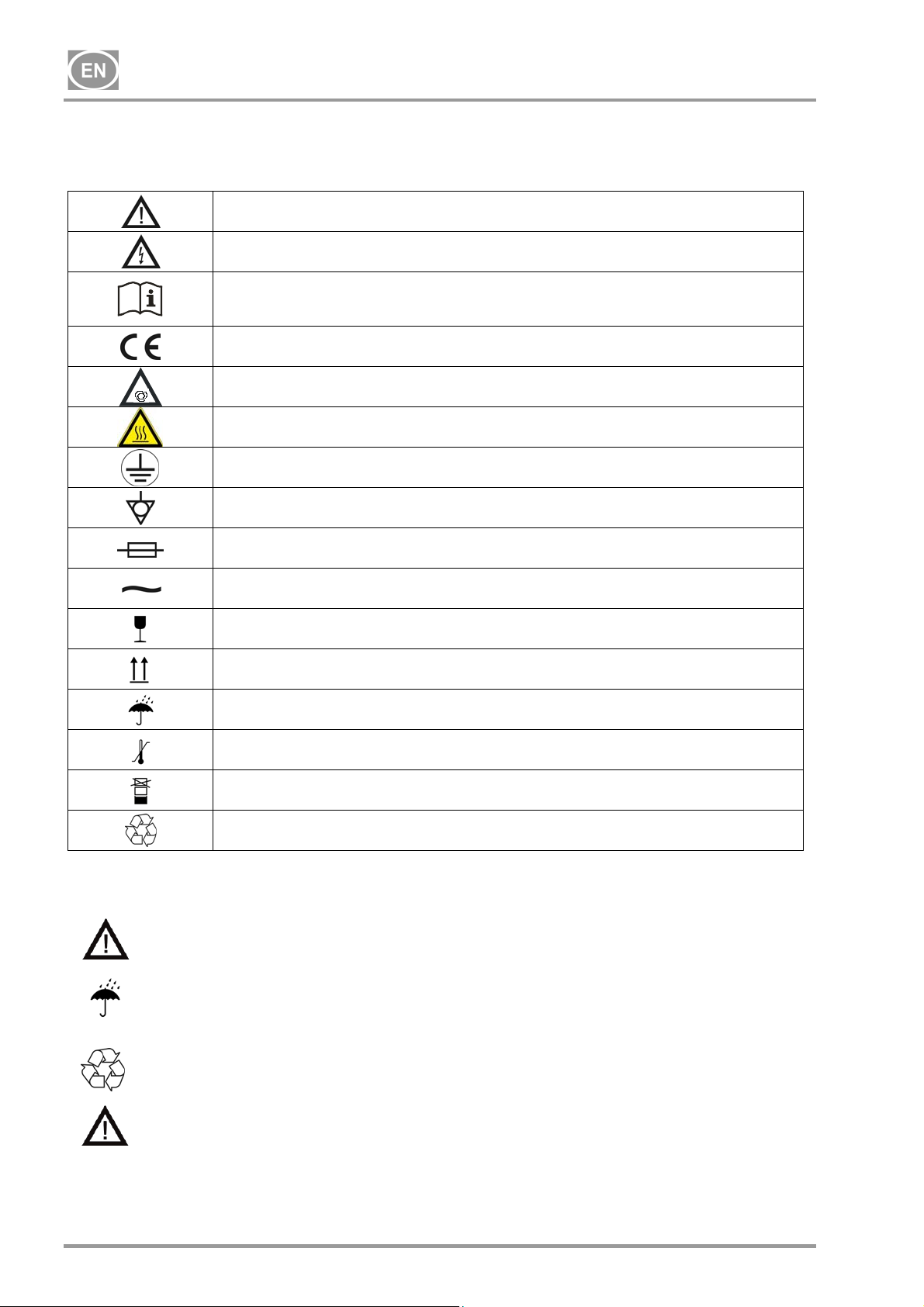
3. ALERT NOTICES AND SYMBOLS
In the Installation, Operation and Maintenance Manual and on packaging and product, the following labels or
symbols are used for important information:
Attention, see instructions for use
Caution, risk of electric shock
Consult instructions for use
CE mark of compliance
Compressor is remote-controlled and may start without warning
Caution! Hot surface
Earth (ground) connection
Terminal for ground connection
Fuse
Alternating current
Handling mark on package – FRAGILE
4. STORAGE AND TRANSPORT
The compressor is shipped in cardboard that protects the appliance from damage during transport.
Caution! For transport, always use the original packaging and secure the compressor
in the upright position.
Protect the compressor from humidity and extreme temperatures during transport and storage.
A compressor in its original packaging can be stored in a warm, dry and dust-free area. Do not
store near any chemical substances.
Keep packaging material if possible. If not, please dispose of the packaging material in an
environmentally friendly way and recycle if possible.
Caution! Before moving or transporting the compressor, release all the air pressure from
the tank and hoses and drain the condensed water.
Handling mark on package – THIS SIDE UP
Handling mark on package – KEEP DRY
Handling mark on package – TEMPERATURE LIMITATIONS
Handling mark on package – LIMITED STACKING
Mark on package – RECYCLABLE MATERIAL
NP-DK50 4VR50-11_04-2018 - 4 - 04/2018
DK50 4VR/50
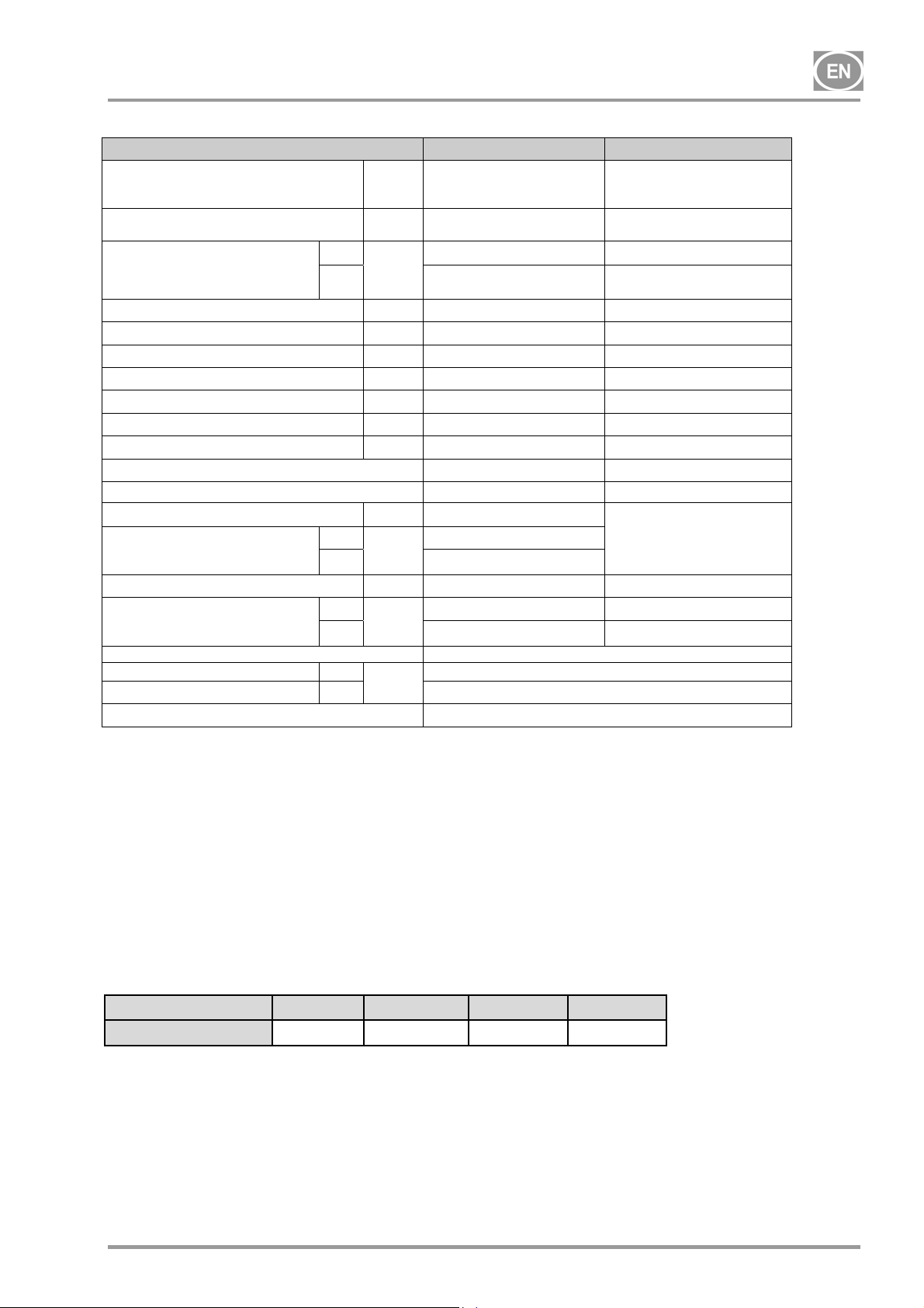
5. TECHNICAL DATA
Rated voltage /
frequency
Compressor output
at pressure of 6 bar
Compressor output at 6 bar with
dryer
Peak compressor current
Maximum compressor current with dryer A
Motor output kW
Air tank capacity L
Working pressure bar
Maximum operating pressure of safety valve bar
Noise L
Mode of operation
Mode of operation with dryer
Compressor dimensions W x L x H
Dimensions
with dryer
W x L x H
Weight
Weight
with dryer
Air dryer performance
Atmospheric dew point
Pressure dew point
Configuration pursuant to STN EN 60 601-1
V / Hz
L.min-1
MD
L.min
NDM
A
pfA
mm
MD
mm
NDM 580x635x790
kg
MD
kg
NDM
MD
°C
NDM
-1
[dB]
DK50 4VR/50 DK50 4VR/50S
3x400/50 3x400/50
250 250
200 200
180 180
4.7 5.1
4.8 5.2
2.2 2.2
50 50
6.0 – 8.0 6.0 – 8.0
12.0 12.0
77 58
Continuous S1 Continuous S1
Continuous S1 Continuous S1
580x580x790
580x635x790
70 128
81 139
89 147
- Air leaving the dryer is filtered using a 5 µm filter at a minimum.
Climatic conditions during storage and transport
Temperature : –25°C to +55°C, 24 h to +70°C
Relative air humidity : 10% to 90 % (no condensation)
Climatic operation conditions
Temperature : +5°C to +40°C
Relative air humidity : 70%
5.1. FAD efficiency correction for differences in elevation
750x770x1015
-20
-40
Type B, class I.
FADcorrectiontable
Elevation[mamsl] 0‐1500 1501‐2500 2501‐3500 3501‐4500
FAD[l/min] FADx1 FADx0.8 FADx0.71 FADx0.60
FAD efficiency refers to conditions at an elevation of 0 mamsl: Temperature: 20°C
Atmospheric pressure: 101325 Pa
Relative humidity: 0%
04/2018 - 5 - NP-DK50 4VR50-11_04-2018
DK50 4VR/50
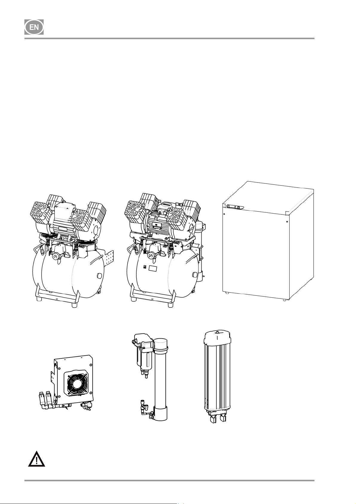
6. PRODUCT DESCRIPTION
6.1. Model variations and their uses
Compressors are the source of clean, oil-free compressed air used to drive dental appliances and
equipment.
Compressors models are designed for the following uses:
Dental compressors DK50 4VR/50 - are designed for independent installation in a suitable environment.
Dental compressors DK50 4VR/50/M - are designed for independent installation in a suitable
environment and are equipped with an air dryer. (MD, NDM )
Dental compressors DK50 4VR/50S - are installed in cabinets with efficient noise mufflers and are
suitable for use in office environments.
Dental compressors DK50 4VR/50S/M - are installed in cabinets and are equipped with air dryers.
(MD, NDM )
DK50 4VR/50
COOLER
Without additional filtration equipment, the compressed air from a compressor is not
suitable for the operation of breathing appliances or similar equipment.
DK50 4VR/50/M
MEMBRANE
DRYER
DK50 4VR/50S/M
DRYER NDM
NP-DK50 4VR50-11_04-2018 - 6 - 04/2018
DK50 4VR/50
6.2. Optional accessories
Products may be equipped with optional accessories that are not included with the basic product
and must be ordered separately:
Filter regulator / set 603022106-000 /
The filter regulator filters out impurities in the compressed air down to a size
of 5 m. The use of this accessory on a compressor without a dryer partially
reduces moisture content in the supplied compressed air. Filtered
compressed air is suitable for use anywhere its parameters meet the
stipulated requirements. The regulator ensures a supply of output air at a
constant pressure (so long as the pressure value set on the regulator is not
higher than the switching pressure set on the pressure switch).
Regulator / set 603022104-000 /
The regulator ensures a supply of output air at a constant pressure (so long
as the pressure value set on the regulator is not higher than the switching
pressure set on the pressure switch).
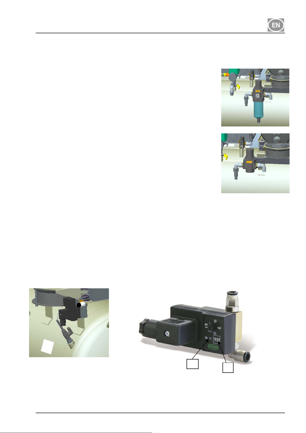
Automatic condensate drain / set 603013114-000 /
The automatic condensate drain automatically drains condensate from the compressor's air tank based on a
pre-set time interval.
The drain automatically opens a solenoid valve at a pre-set time interval to drain condensate from the air
tank.
A timer is used to set the time between actuation of the solenoid valve (approximately 30 minutes).
The time between actuations of the solenoid valve can be adjusted to a lower value if excessive amount
of condensate is generated.
- The TEST button (2) is used to check the actuation of the solenoid valve, and when pushed the
solenoid valve should open (ON) and the time between actuations of the solenoid valve begins from this
point.
- The LED (1) lights up to signalize the valve is open(ON).
1
2
04/2018 - 7 - NP-DK50 4VR50-11_04-2018
DK50 4VR/50
7. FUNCTION
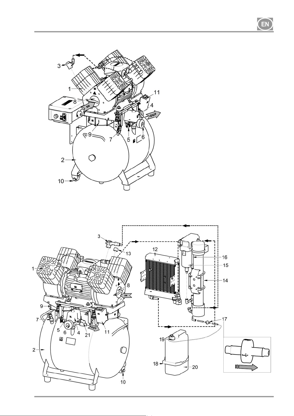
Compressor (Fig.1)
The compressor (1) draws in air through a filter (8) and compresses it through a check valve (3) into an air
tank (2). The connected apparatus draws the compressed air from the air tank until the pressure drops to a
default preset level on the air-pressure switch (4) switching the compressor on. The compressor again
compresses air into the nozzle until the maximum pressure is reached and the compressor switches off.
Safety valve (5) prevents the pressure in air chamber from rising above the maximal allowed value. The
drain valve (7) releases the condensate from the air nozzle. Compressed, dry and clean air is then ready for
additional use in the air tank.
Compressor with membrane dryer (MD) (Fig. 2)
The compressor (1) draws in air through an inlet filter (8) and compresses it into a cooler (12). The air then
passes through a filter (16) and micro-filter (15) into the dryer (14) with the dry and clean air passing through
a check valve (3) to the air tank (2). Condensate from the filter and micro-filter is automatically released into
a drainage vessel. The dryer ensures continuous drying of the compressed air. Compressed, dry and clean
air is then ready for additional use in the air tank.
Compressor with NDM dryer (Fig. 3)
The compressor (1) draws in air through an inlet filter (8) and compresses it into the cooler. The air then
passes through the dryer chamber (23) containing the adsorbent media where moisture is removed and then
out via the check valve (3) and into the air tank (2). The adsorbent media regenerates when the drying
chamber is being evacuated, always after the compressor is switched off by the pressure switch. The air is
then released from the adsorption chamber via the open solenoid valve as it is evacuated using dry
compressed air. Air drying occurs in one chamber while regeneration occurs in the other chamber. The
mode of each chamber changes in regular cycles and the drying and regeneration processes are then
performed in the alternate chamber. Compressed, dry and clean air is then ready for additional use.
The pressure switch (24) protects the dryer from damage if the compressor operates for an extended period
of time at low pressure (less than 5 bar)
Compressor cabinet (Fig. 4)
The soundproof cabinet itself is compact yet allows sufficient exchange of cooling air. The fan (9) underneath
the compressor aggregate and the cabinet fans (33) cool the compressor and the space inside the cabinet.
The fans operate when the compressor motor is running. The cooling fans automatically start if the
temperature in the cabinet reaches over 40°C, even when the compressor is not running. The fans
automatically switch off once the cabinet temperature drops to around 32°C.
An indicator (34) located on the front of the cabinet indicates maintenance is needed on the compressor with
the NDM dryer unit (see the Maintenance Interval chapter)
Make sure that nothing impedes the free flow of air under and around the compressor.
Never cover the hot air outlet on the top back side of the case.
If placing the compressor on a soft floor such as carpet, create space for ventilation
between the base and floor or the box and floor, e.g. underpin the footings with hard pads.
NP-DK50 4VR50-11_04-2018 - 8 - 04/2018
DK50 4VR/50
Fig. 1 - Compressor
Fig. 2 - Compressor with membrane dryer (MD)
1. Compressor
2. Air tank
3. Check valve
4. Pressure switch
5. Safety valve
6. Pressure gauge
7. Condensate drain valve
8. Inlet filter
9. Compressor fan
10. Compressor wheel
11. Hour meter
12. Dryer cooler
13. Plug
14. Membrane dryer (MD)
15. Micro-filter
16. Filter
17. Check valve
18. Magnetic bracket
19. Plug
20. Condensate vessel
21. Outlet valve
22. Exhaust muffler
23. Adsorption dryer (NDM)
24. Pressure switch 2
25. Cabinet pressure gauge
26. Switch
27. all bump stop
28. Cabinet connector
29. Pressure gauge hose
30. Supporting bracket
31. Compressor wheel
32. Positioning truck
33. Cabinet fan
34. Maintenance indicator
04/2018 - 9 - NP-DK50 4VR50-11_04-2018
 Loading...