

EKOM DK50 2x4VR/110, DK50 2x4VR/110S, DK50 2x4VR/110/M, DK50 2x4VR/110S/M Installation, Operation And Maintenance Manual
Page 1
Page 2

DK50 2x4VR/110
NP-DK50 2x4VR110-12_10-2016 - 2 - 10/2016
CONTENTS
IMPORTANT INFORMATION ................................................................................................................. 3
1. CE MARKING ............................................................................................................................ 3
2. WARNINGS ................................................................................................................................ 3
3. ALERT NOTICES AND SYMBOLS ............................................................................................ 4
4. STORAGE AND TRANSPORT .................................................................................................. 4
5. TECHNICAL DATA ..................................................................................................................... 5
6. PRODUCT DESCRIPTION ........................................................................................................ 6
7. FUNCTION ................................................................................................................................. 8
INSTALLATION ..................................................................................................................................... 11
8. USE ........................................................................................................................................... 11
9. INSTALLATION ........................................................................................................................ 11
10. WIRING DIAGRAMS ............................................................................................................... 16
11. PNEUMATIC DIAGRAM .......................................................................................................... 18
12.FIRST OPERATION ................................................................................................................. 19
OPERATION .......................................................................................................................................... 19
13.SWITCHING THE COMPRESSOR ON ................................................................................... 20
MAINTENANCE .................................................................................................................................... 21
14.MAINTENANCE SCHEDULE ................................................................................................. 21
15.MAINTENANCE ........................................................................................................................ 21
16.STORAGE ................................................................................................................................ 25
17.DISPOSING OF THE APPLIANCE .......................................................................................... 25
18.REPAIR SERVICE .................................................................................................................... 25
19.SOLVING PROBLEMS ............................................................................................................. 2 5
Page 3

DK50 2x4VR/110
10/2016 - 3 - NP-DK50 2x4VR110-12_10-2016
IMPORTANT INFORMATION
1. CE MARKING
Products labeled with the CE mark of compliance meet the safety guidelines (93/42/EEC) of the European
Union.
2. WARNINGS
2.1. General warnings
This Installation, Operation and Maintenance Manual is a part of the appliance and must be kept with the
compressor. Careful review of this manual will provide the information necessary for correct operation of the
appliance.
The safety of operating personnel and trouble-free operation of the appliance are guaranteed only if
original parts are used. Only accessories and parts mentioned in the technical documentation or expressly
approved by the manufacturer can be used.
If any other accessories or consumable materials are used, the manufacturer cannot be held responsible
for the safe operation of the appliance. This guarantee does not cover damages originating from the use of
accessories or consumable material other than those specified or suggested by the manufacturer.
The manufacturer guarantees the safety, reliability and function of the appliance only if:
- Installation, new settings, amendments, extensions and repairs are performed by the manufacturer or
its representative, or a service provider authorized by the manufacturer
- The appliance is used in accordance with this Installation, Operation and Maintenance Manual
The manufacturer reserves all rights for the protection of its wiring diagrams, methods and names.
Translation of Manual for Installation, Operation and Maintenance is carried out in accordance with the
best knowledge. In the case of ambiguities, the Slovak version of the text prevails.
2.2. General safety warnings
The manufacturer developed and designed the equipment in such a way so that any risks were excluded if it
is used according to intention. The manufacturer considers it to be its obligation to describe the following
safety measures in order to exclude residual damages.
Operation of the appliance must be in compliance with all local codes and regulations.
Original packaging should be kept for the return of the appliance. Only the original packaging ensures
protection of the appliance during transport. If it is necessary to return the appliance during the guarantee
period, the manufacturer is not liable for damages caused by improper packaging.
Each time the appliance is used, the operator must make sure that it is functioning correctly and safely.
The user must fully understand the operation of the appliance.
The product is not intended for operation in areas with a risk of explosion.
If any problem occurs during use of the appliance, the user must inform his supplier immediately.
2.3. Electrical system safety warnings
The appliance must be connected to earth (grounded).
Before the appliance is plugged in, make sure that the mains voltage and mains frequency stated on the
appliance are the same as the power mains.
Prior to putting into operation it is necessary to check for possible damage of the equipment and
connected air and electric distributions. Damaged pneumatic and electric lines must be immediately
replaced.
Immediately disconnect the appliance from the mains (pull out mains plug) if a technical failure occurs.
During repairs and maintenance, ensure that:
- The mains plug is pulled out from the socket
- Pressure pipes are vented and pressure is released from the air tank.
The appliance must be installed by an approved, qualified technician.
Page 4
DK50 2x4VR/110
NP-DK50 2x4VR110-12_10-2016 - 4 - 10/2016
3. ALERT NOTICES AND SYMBOLS
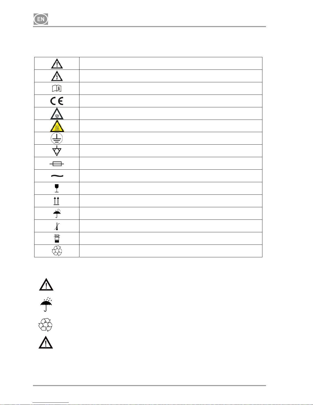
In the Installation, Operation and Maintenance Manual and on packaging and product, the following labels or
symbols are used for important information:
Information, instructions and cautions for the prevention of damage to health or
materials
Caution! Dangerous electrical voltage
Read the user manual!
CE mark of compliance
Compressor is remote-controlled and may start without warning
Caution! Hot surface
Earth (ground) connection
Terminal for ground connection
Fuse
Alternating current
Handling mark on package – FRAGILE
Handling mark on package – THIS SIDE UP
Handling mark on package – KEEP DRY
Handling mark on package – TEMPERATURE LIMITATIONS
Handling mark on package – LIMITED STACKING
Mark on package – RECYCLABLE MATERIAL
4. STORAGE AND TRANSPORT
The compressor is shipped in cardboard that protects the appliance from damage during transport.
Caution! For transport, always use the original packaging and secure the compressor
in the upright position.
Protect the compressor from humidity and extreme temperatures during transport and storage.
A compressor in its original packaging can be stored in a warm, dry and dust-free area. Do not
store near any chemical substances.
Keep packaging material if possible. If not, please dispose of the packaging material in an
environmentally friendly way and recycle if possible.
Caution! Before moving or transporting the compressor, release all the air pressure
from the tank and hoses and drain the condensed water.
Page 5
DK50 2x4VR/110
10/2016 - 5 - NP-DK50 2x4VR110-12_10-2016
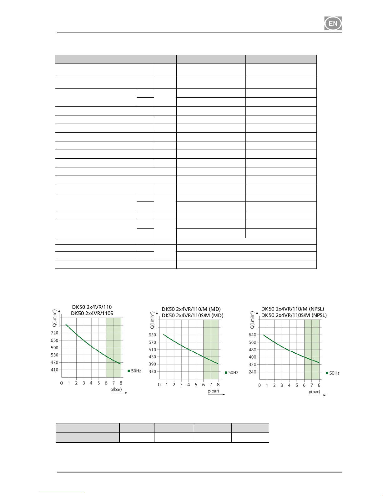
5. TECHNICAL DATA
DK50 2x4VR/110
DK50 2x4VR/110S
Rated voltage /
frequency
V / Hz
3x400/50 3x400/50
Compressor output
at pressure of 6 bar
Lit.min-1
520 520
Compressor output at 6 bar with
dryer
MD
Lit.min
-1
430 430
NDL
400 400
Maximum compressor current
A
9.4 10.2
Maximum compressor current with dryer A
10.1 10.6
Motor output kW
2x2.2 2x2.2
Air tank capacity Lit.
110 110
Working pressure bar
6.0 – 8.0
6.0 – 8.0
Maximum operating pressure of safety valve bar
9.0 9.0
Noise L
pfA
[dB]
77 58
Mode of operation
Continuous S1 Continuous S1
Mode of operation with dryer
Continuous S1 Continuous S1
Compressor dimensions W x L x H
mm
1090x500x830 1260x795x1025
Dimensions
with dryer
W x L x H
MD
mm
1210x670x830
1550x795x1240
NDL 1210x770x1240
1550x795x1240
Weight
kg
136 218
Weight
with dryer
MD
kg
158 240
NDL
172 252
Air dryer performance
Atmospheric dew point
MD
°C
-20
Pressure dew point
NDL
- 35
Configuration pursuant to EN 60 601-1
Type B, class I.
Climatic conditions during storage and transport
Temperature : –25°C to +55°C, 24 h to +70°C
Relative air humidity : 10% to 90 % (no condensation)
Climatic operation conditions
Temperature : +5°C to +40°C
Relative air humidity : 70%
5.1. FAD efficiency correction for differences in elevation
FADcorrectiontable
FAD efficiency refers to conditions at an elevation of 0 mamsl: Temperature: 20°C
Atmospheric pressure: 101325 Pa
Relative humidity: 0%
Elevation[mamsl] 0‐1500 1501‐2500 2501‐3500 3501‐4500
FAD[l/min] FADx1 FADx0.8 FADx0.71 FADx0.60
Page 6
DK50 2x4VR/110
NP-DK50 2x4VR110-12_10-2016 - 6 - 10/2016
6. PRODUCT DESCRIPTION
6.1. Model variations and their uses
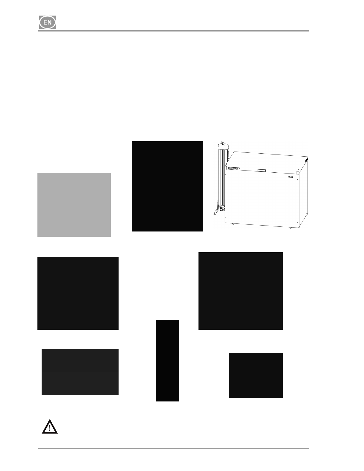
Compressors are the source of clean, oil-free compressed air used to drive dental appliances and
equipment.
Compressors models are designed for the following uses:
Dental compressors DK50 2x4VR/110 - are designed for independent installation in a suitable
environment.
Dental compressors DK50 2x4VR/110/M - are designed for independent installation in a suitable
environment and are equipped with an air dryer.
Dental compressors DK50 2x4VR/110S - are installed in cabinets with efficient noise mufflers and are
suitable for use in office environments.
Dental compressors DK50 2x4VR/110S/M - are installed in cabinets and are equipped with air dryers.
DK50 2x4VR/110 DK50 2x4VR/110/M (NDL) DK50 2x4VR/110S/M
DK50 2x4VR/110/M (MD) S110R
DRYER MD WITH COOLER DRYER NDL COOLER
Without additional filtration equipment, the compressed air from a compressor is not
suitable for the operation of breathing appliances or similar equipment.
Page 7
DK50 2x4VR/110
10/2016 - 7 - NP-DK50 2x4VR110-12_10-2016
6.2. Optional accessories
Products may be equipped with optional accessories that are not
included with the basic product and must be ordered separately:
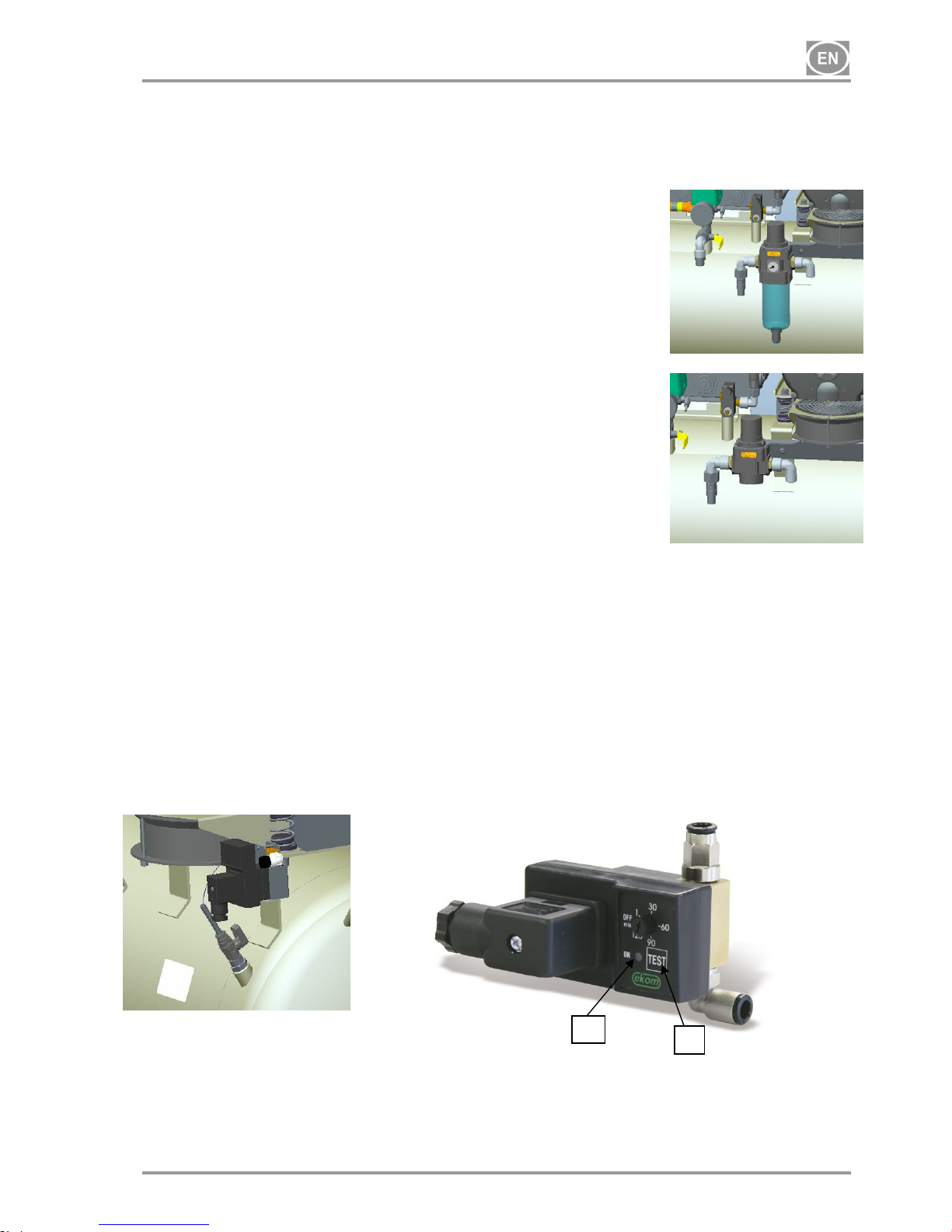
Filter regulator / set 604012967-000 /
The filter regulator filters out impurities in the compressed air down to a size
of 5 m. The use of this accessory on a compressor without a dryer partially
reduces moisture content in the supplied compressed air. Filtered
compressed air is suitable for use anywhere its parameters meet the
stipulated requirements. The regulator ensures a supply of output air at a
constant pressure (so long as the pressure value set on the regulator is not
higher than the switching pressure set on the pressure switch).
Regulator / set 604022073-000 /
The regulator ensures a supply of output air at a constant pressure (so long
as the pressure value set on the regulator is not higher than the switching
pressure set on the pressure switch).
Automatic condensate drain / set 604011998-000 /
The automatic condensate drain automatically drains condensate from the compressor's air tank based on a
pre-set time interval.
The drain automatically opens a solenoid valve at a pre-set time interval to drain condensate from the air
tank.
A timer is used to set the time between actuation of the solenoid valve (approximately 30 minutes).
The time between actuations of the solenoid valve can be adjusted to a lower value if excessive amount
of condensate is generated.
- The TEST button (2) is used to check the actuation of the solenoid valve, and when pushed the
solenoid valve should open (ON) and the time between actuations of the solenoid valve begins from this
point.
- The LED (1) lights up to signalize the valve is open(ON).
1
2
Page 8
DK50 2x4VR/110
NP-DK50 2x4VR110-12_10-2016 - 8 - 10/2016
7. FUNCTION
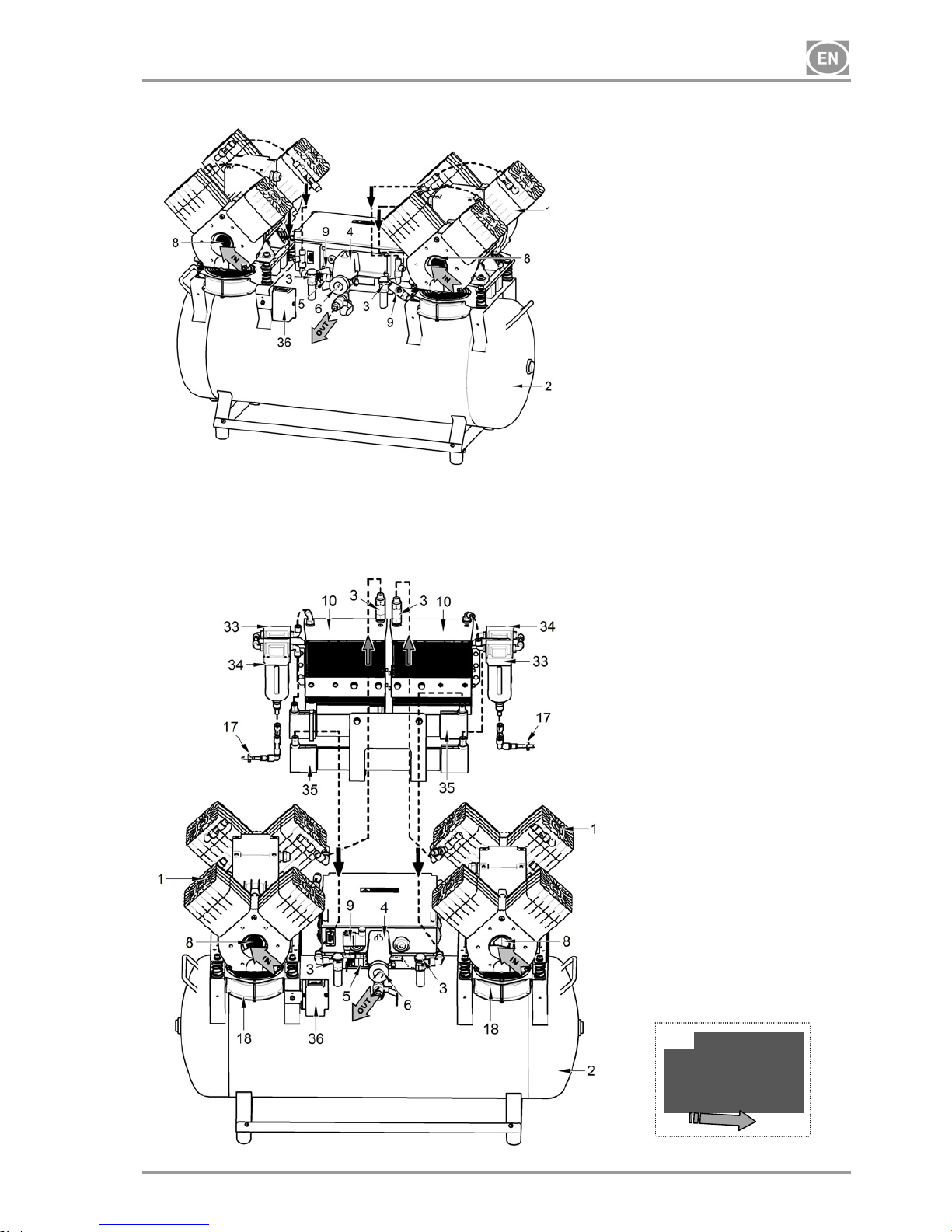
Compressor (Fig.1)
The compressor (1) draws in air through a filter (8) and compresses it through a check valve (3) into an air
tank (2). The connected apparatus draws the compressed air from the air tank until the pressure drops to a
default preset level on the air-pressure switch (4) switching the compressor on. The compressor again
compresses air into the nozzle until the maximum pressure is reached and the compressor switches off.
After compressor aggregate is switched off, pressure hose shall be pressure-release solenoid valve (9).
Safety valve (5) prevents the pressure in air chamber from rising above the maximal allowed value. The
drain valve (7) releases the condensate from the air nozzle. Compressed, dry and clean air is then ready for
additional use in the air tank.
Compressor with membrane dryer (MD) (Fig. 2)
The compressor (1) draws in air through an inlet filter (8) and compresses it through a check valve (3) into a
cooler (10). The air then passes through a filter (33) and micro-filter (34) into the dryer (35) with the dry and
clean air passing through a check valve (3) to the air tank (2). Condensate from the filter and micro-filter is
automatically released into a drainage vessel. The dryer ensures continuous drying of the compressed air.
Compressed, dry and clean air is then ready for additional use in the air tank.
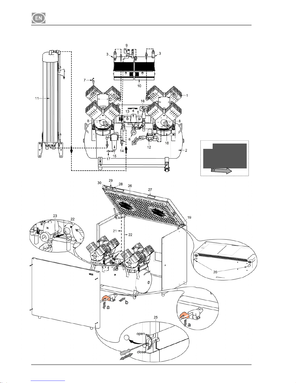
Compressor with NDL dryer (Fig. 3)
The compressor (1) draws in air through an inlet filter (8) and compresses it through a check valve (3) into
the cooler (10). The air then proceeds through the condensate separator (15) and the drying chamber (11)
with the adsorbent media where moisture is removed and then on to the air tank (2). The adsorbent media
regenerates when the drying chamber is being evacuated, always after the compressor is switched off by the
pressure switch. The air is then released from the adsorption chamber via the open solenoid valve as it is
evacuated using dry compressed air. Air drying occurs in one chamber while regeneration occurs in the
other chamber. The mode of each chamber changes in regular cycles and the drying and regeneration
processes are then performed in the alternate chamber. Compressed, dry and clean air is then ready for
additional use. Constant output pressure is maintained by the pressure regulator (12).
The pressure switch (13) protects the dryer from damage if the compressor operates for an extended period
of time at low pressure (less than 5 bar)
Compressor cabinet (Fig. 4)
The soundproof cabinet itself is compact yet allows sufficient exchange of cooling air.
The fan (18) underneath the compressor aggregate and the cabinet fans (26) cool the compressor and the
space inside the cabinet. The fans operate when the compressor motor is running. The cooling fans
automatically start if the temperature in the cabinet reaches over 40°C, even when the compressor is not
running. The fans automatically switch off once the cabinet temperature drops to around 32°C.
An indicator (29) located on the front of the cabinet indicates maintenance is needed on the compressor with
the NDL dryer unit (see the Maintenance Interval chapter)
Make sure that nothing impedes the free flow of air under and around the compressor.
Never cover the hot air outlet on the top back side of the case.
If placing the compressor on a soft floor such as carpet, create space for ventilation
between the base and floor or the box and floor, e.g. underpin the footings with hard pads.
Page 9
DK50 2x4VR/110
10/2016 - 9 - NP-DK50 2x4VR110-12_10-2016
Fig. 1 - Compressor
Fig.2- Compressor with membrane dryer (MD)
1. Compressor
2. Air tank
3. Check valve
4. Pressure switch
5. Safety valve
6. Pressure gauge
7. Condensate drain valve
8. Inlet filter
9. Solenoid valve
10. Dryer cooler
11. Adsorption dryer (NDL)
12. Pressure regulator (Optional accessories)
13. Pressure switch 2
14. Pressure relief valve
15. Condensate separator
16. Control valve
17. Check valve
18. Compressor fan
19. Box gas springs
20. Wall bump stop
21. Power supply cord
22. Pressure gauge hose
23. Angular screwing
24. -
25. Compressor wheel
26. Cabinet fan
27. Handle
28. Switch
29. Maintenance indicator
30. Cabinet pressure gauge
31. Temperature switch
32. Positioning truck
33. Filter
34. Micro-filter
35. Membrane dryer (MD)
36. Hour meter
17
Page 10
DK50 2x4VR/110
NP-DK50 2x4VR110-12_10-2016 - 10 - 10/2016
Fig. 3 - Compressor with adsorption dryer (NDL)
Fig. 4 - Cabinet
17
Page 11
DK50 2x4VR/110
10/2016 - 11 - NP-DK50 2x4VR110-12_10-2016
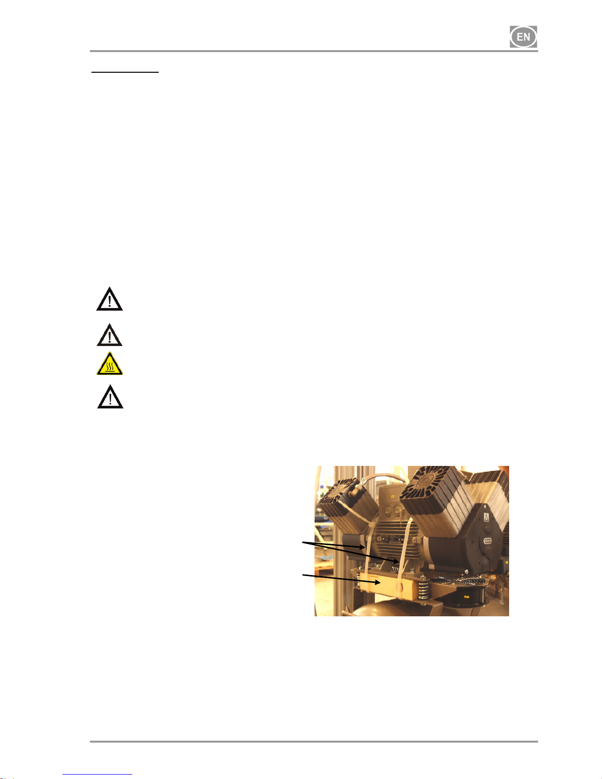
Unpacking Fig.5
INSTALLATION
8. USE
The appliance must be installed and operated in a dry, well ventilated and dust-free area where ambient
temperature is within the range of +5°C to +40°C and relative air humidity does not exceed 70%. Otherwise,
failure-free operation of the compressor cannot be guaranteed. The compressor must be installed so that it
is accessible at all times for operation and maintenance. Please ensure that the appliance label is
accessible.
The appliance must stand on a flat, sufficiently stable base. See paragraph 5 (Technical data) when
positioning or lifting the compressor.
Compressors cannot be exposed to outdoor environments. The appliance cannot be used in moist or wet
environments. Do not use the compressor in the presence of explosive gases, dust or combustible liquids.
Before connecting the compressor to medical equipment, the supplier must confirm that it meets all
requirements for its use. Refer to the technical data of the product for this purpose. When a unit is to be
built-in, classification and evaluation of compatibility must be done by the manufacturer or supplier of the
product to be used.
Any use other than that described in this manual is not covered by the guarantee, and the manufacturer is
not liable for any damages that may result. The operator/user assumes all risk.
9. INSTALLATION
Only qualified personnel can install and start up the appliance and train operating
personnel in its correct use and maintenance. Installation and training of all operators
shall be confirmed by the installer’s signature on the certificate of installation.
Prior to installation, ensure that the compressor is free of all transport packaging and
stabilizers to avoid any risk of damage to the product.
Caution! When in operation, the compressor is hot. Burns or fire may result if contact is
made by the operator or any flammable material.
Electric cord for connection to electric mains and air hoses may not be broken. The power
cord may not be exposed to pulling, pressure and excessive heat.
9.1. Placement of the compressor
Dental compressor DK50 2x4VR/110 (Fig. 5)
After removing all packaging material, place the product on the floor and remove the stabilization parts (X
and Y). Connect the equipment to the compressor using suitable means. Insert the mains plug into a rated
outlet circuit.
Dental compressor DK50 2x4VR/110/M (MD) (Fig 5).
After unpacking the equipment, position it on the floor and free it from all packing materials and remove the
fixation components (X and Y) - see Detail A. Connect the outlet pressure hose to the connector on the
device. Insert the mains plug into a rated outlet circuit.
X
Y
Page 12
DK50 2x4VR/110
NP-DK50 2x4VR110-12_10-2016 - 12 - 10/2016
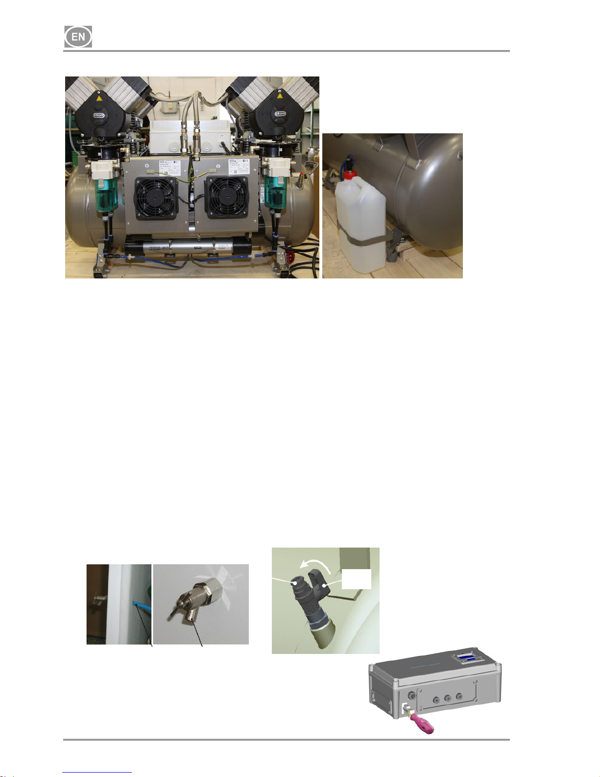
Fig.6
Connect the hoses for the condensate drain to the condensate vessel.
Dental compressor DK50 2x4VR/110/M (NDL) (Fig. 5)
After removing all packaging material, place the product on the floor and remove the stabilization parts (X
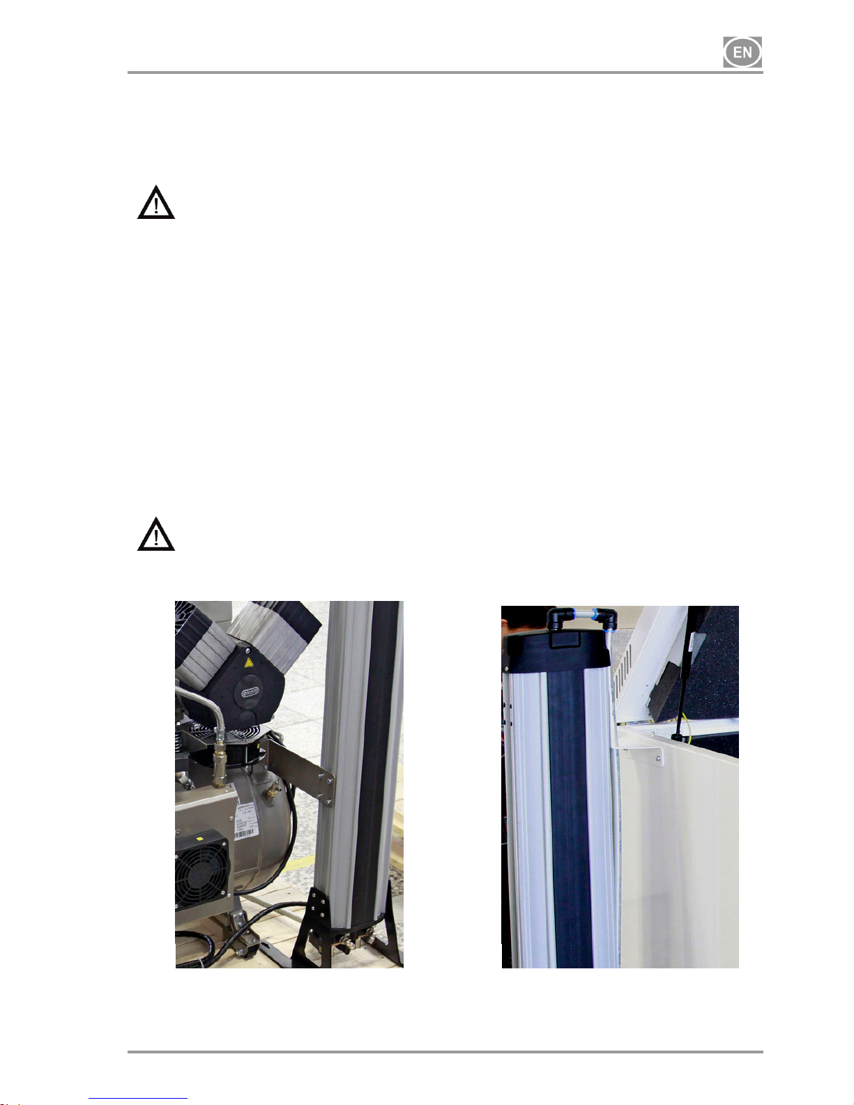
and Y). Place the dryer on the floor and attach it to the compressor using the bolts and washers - Fig. 7.
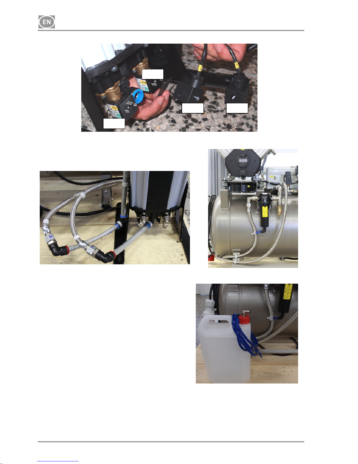
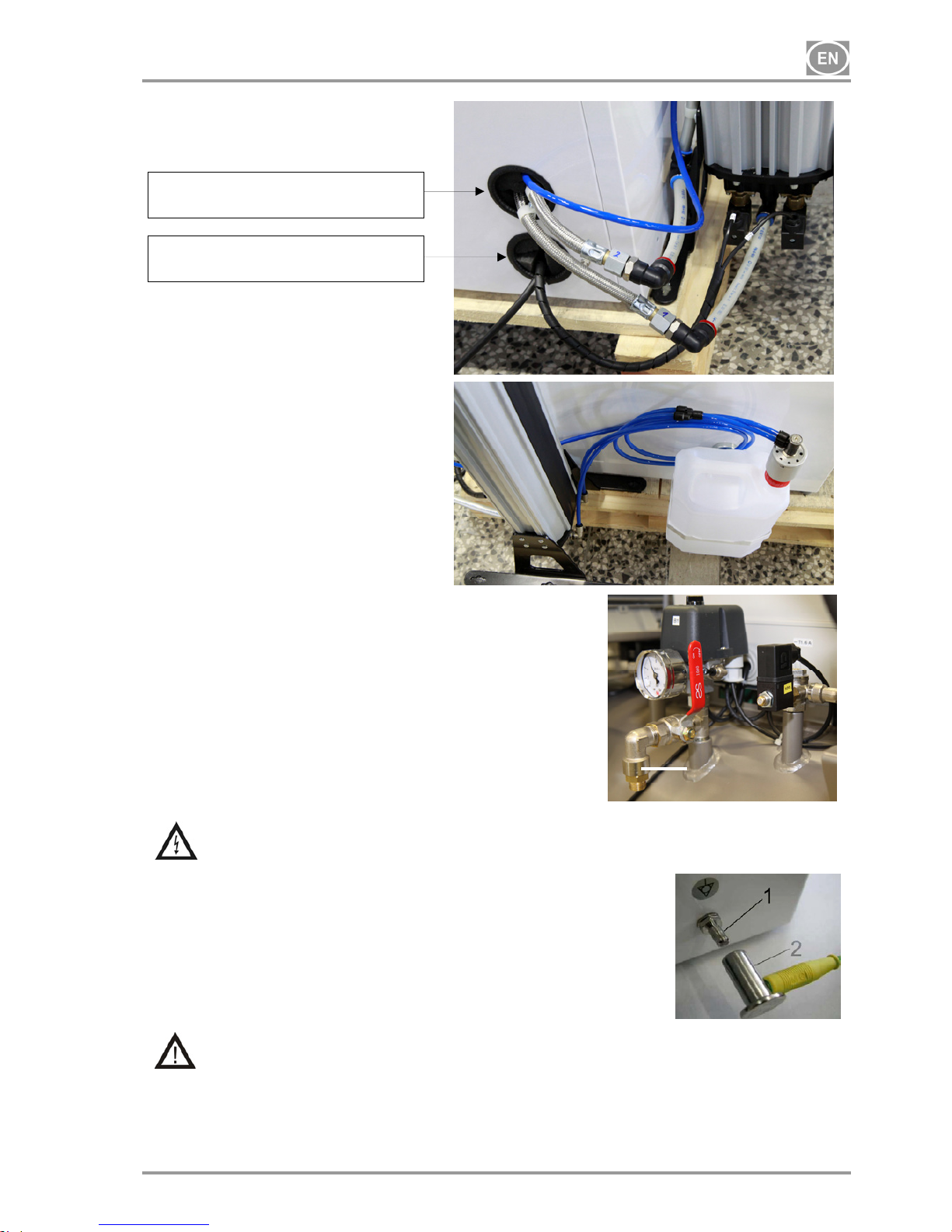
Connect the compressor to the dryer using hoses following Fig. 10 and 11. Install the washer on the solenoid
valves and connect the connectors following Fig. 9. Connect the equipment to the compressor using suitable
means. Insert the mains plug into a rated outlet circuit. Connect the condensate drain hose from the
condensate separator to the condensate vessel.
Cabinet-mounted dental compressor DK50 2x4VR/110S (Fig.4 and Fig. 5)
After removing all packaging material, place the product on the floor and remove the stabilization parts (X
and Y). Install the 2 wall bump stops on the compressor cabinet (20) on the rear and upper portion of the
cabinet and position the cabinet in the desired location. The bump stops ensure that the cabinet is properly
spaced from the wall for ventilation purposes. The 4 screws need to be removed and the front panel of the
cabinet must be removed in order to install the compressor in the cabinet. Connect the cabinet connector
(21) to the compressor. Place the pressure hose and the power cord through the opening in the rear lower
portion of the cabinet following Fig. 13.
Install the fitting with the valve (37) into the opening in the side of the cabinet and install the PA Ø6/Ø4 hose
(38). Blind the opening on the opposite side of the cabinet with a Ø16.5 plug. (The customer determines on
which side to install the fitting with the valve). Insert the hose (38) provided with the standard product into
the drain valve (39) and install the other end on the valve inside the cabinet. Open the drain valve on the air
tank. Please note, the numbered codes are taken from product 2x2V.
Pick up the compressor using the handle and use the positioning truck (32) and the installed wheels to
position it inside the cabinet. Install the cabinet's hose (22) and pressure gauge (30) into the quick coupling
on the compressor and reinstall the front panel. Connect the equipment to the compressor using suitable
means. Connect the mains plug to a properly rated outlet circuit.
A screwdriver must be used to disconnect the cabinet
connector if the compressor is being disassembled!
(Fig.6)
38 37
39
Page 13
DK50 2x4VR/110
10/2016 - 13 - NP-DK50 2x4VR110-12_10-2016
Cabinet-mounted dental compressor DK50 2x4VR/110S/M (MD) (Fig.4, Fig.5)
After removing all packaging material, place the product on the floor and remove stabilization parts X and Y
(Detail A). Place the compressor into the cabinet using the procedure defined above. Before the compressor
is installed in the cabinet, the hose(s) for the condensate drain must be passed through the opening on the
back side of the cabinet and connected to the condensate vessel. Blind the openings on the sides of the
cabinet with Ø16.5 plugs.
The condensate vessel must be on the floor in order to ensure the dryer operates properly.
Otherwise the dryer may be damaged.
Cabinet-mounted compressor DK50 2x4VR/110S/M (NDL) (Fig. 4 and Fig. 5)
After unpacking the equipment, position it on the floor and remove all packing materials and the stabilization
parts (X and Y) - see Detail A. Install the 2 wall bump stops on the compressor cabinet (20) on the rear and
upper portion of the cabinet and position the cabinet in the desired location. The bump stops ensure that the
cabinet is properly spaced from the wall for ventilation purposes. The 4 screws need to be removed and the
front panel of the cabinet must be removed in order to install the compressor in the cabinet. Pick up the
compressor using the handle and use the positioning truck (32) and the installed wheels to position it inside
the cabinet. The pressure hoses, condensate drain hose, power cord and connectors must be pulled through
the openings in the rear wall of the cabinet following Fig. 13 once the compressor is installed in the cabinet.
Place the dryer on the floor and attach it to the cabinet using the bolts and washers - Fig. 8. Connect the
compressor to the dryer using the pressure hoses and connectors - Fig. 13. Connect hose "1" to the dryer
inlet marked "1". Connect hose "2" to the dryer outlet marked "2". Install the washer on the solenoid valves
and connect the connectors following the markings - Fig. 9.
Connect the condensate drain hose from the condensate separator to the condensate vessel - Fig. 14.
Connect the cabinet connector (21) to the compressor. Install the cabinet's hose (22) and pressure gauge
(30) into the quick coupling on the compressor and reinstall the front panel. Blind the openings on the sides
of the cabinet with Ø16.5 plugs. Connect the equipment to the compressor using suitable means. Connect
the mains plug to a properly rated outlet circuit.
The condensate vessel must be on the floor in order to ensure the dryer operates properly.
Otherwise the dryer may be damaged.
Dryer installation
DK50 2x4VR/110/M DK50 2x4VR/110S/M
Fig.7 Fig.8
Page 14
DK50 2x4VR/110
NP-DK50 2x4VR110-12_10-2016 - 14 - 10/2016
Connecting the solenoid valve
Connecting hoses
DK50 2x4VR/110/M
M10 M11
M10
M11
Fig.9
Fig.10 Fig.11
Fig.12
2
2
1
1
Page 15
DK50 2x4VR/110
10/2016 - 15 - NP-DK50 2x4VR110-12_10-2016
Fig.15
Fig.16
1
DK50 2x4VR/110S/M
9.2. Compressed air outlet
(Fig.15)
Lead the pressure hose from the output of compressed air (1) to the
appliance – dental set.
9.3. Electrical connection
Plug the electrical cord into the mains.
The appliance is equipped with a grounded plug. Make sure this connection complies
with local electrical codes. The mains voltage and frequency must comply with the data
stated on the appliance label.
(Fig.16)
Keep the socket easily accessible to ensure that in an emergency the
appliance can be safely disconnected from the mains.
Connection to the power distribution box must be max.16 A.
The connection of the earth ground pin 6mm (1) with other
appliances must be completed in accordance with local electrical
codes. The female socket (2), which is not included in the standard
set, is an optional accessory.
Electrical cable may not contact the hot parts of a compressor. Insulation could be
damaged!
If any electrical cord or air hose is damaged it must be replaced immediately.
Opening for the pressure hoses and
condensate drain hose
Opening for electrical cables and
solenoid valve connectors
2
2
1
1
Page 16
DK50 2x4VR/110
NP-DK50 2x4VR110-12_10-2016 - 16 - 10/2016
3/N/PE ~ 400 V 50 Hz
MAINS TN-S [TN-C-S]
ELECTRIC OBJECT 1ST.CAT
TYPE B
1UN
1
2
3
PE
N
-X2
-K3
PE PE PE PE
L1
L2
L3
N
PE
-X4
-X1:2
F3 /1.6A
-F3
-E2 -E3 -E4
PE
-E5 -E6
-P1
h
~
~
-X1:3
-M20
PE
bk-1-11
bk-1-11
bk-1-11
bk-1-40
bk-1-40
bk-0.75-33
bk-0.75-33
bu-0.75-27
gnye-0.75-27
bk-0.75-20
bk-0.75-38 bk-0.75-13
bu-0.75-23
40°C
-B1
-B2
-E1
-M10
-F1
PE
3
~
3
~
L1
L2
L3
N
PE
-X1:1
2
1
4
3
5
6
-F2
PE
-M1
-M2
PS2
2
1
4
3
5
21436504
03
A2
A1
-Q11
M
6
21436504
03
A2
A1
-Q12
M
p >
3/N/PE ~ 400/230 V 50..60 Hz
MAINS TN-S [TN-C-S]
ELECTRIC OBJECT 1ST.CAT
TYPE B
2
1
4
3
5
21436504
03
A2
A1
-Q11
M
6
21436504
03
A2
A1
-Q12
M
p >
40°C
-B1
-B2
-E1
-M10
-F1
PE
3
~
3
~
L1
L2
L3
N
PE
-X1:1
2
1
4
3
5
6
-F2
PE
-M1
-M2
PS2
1UN
1
2
3
PE
N
-X2
-K3
PE PE PE PE
L1
L2
L3
N
PE
-X4
-X1:2
F3 /1.6A
-F3
-E2 -E3 -E4
-P1
h
~
~
-X1:3
-M20
PE
bk-1-11
bk-1-11
bk-1-11
bk-1-40
bk-1-40
bk-0.75-33
bk-0.75-33
bk-0.75-33
bu-0.75-27
gnye-0.75-27
bk-0.75-20
bk-0.75-38 bk-0.75-13
bu-0.75-23
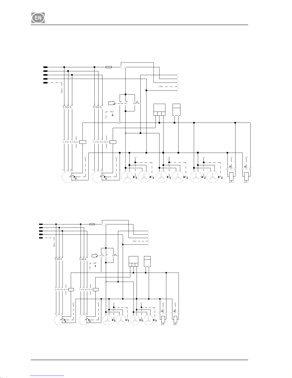
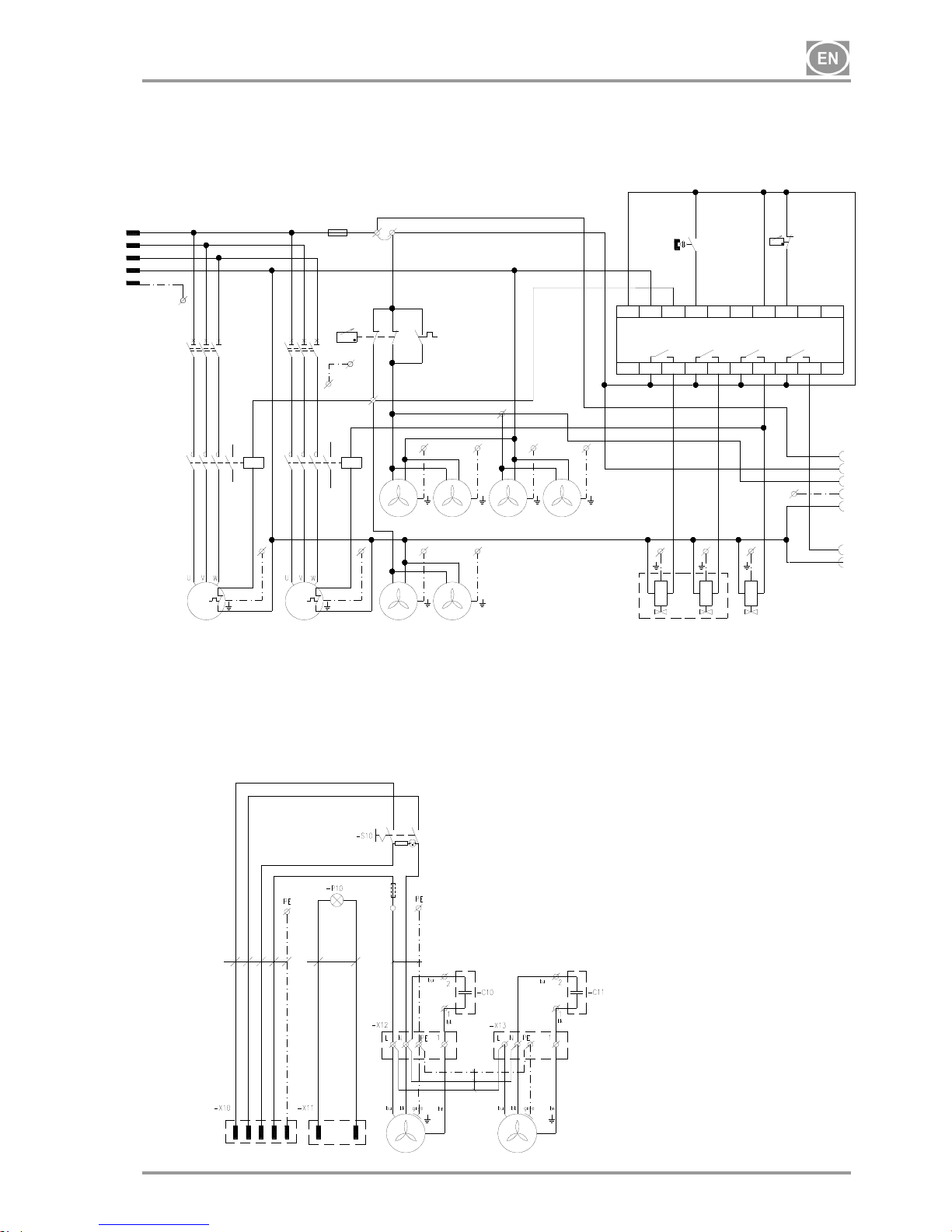
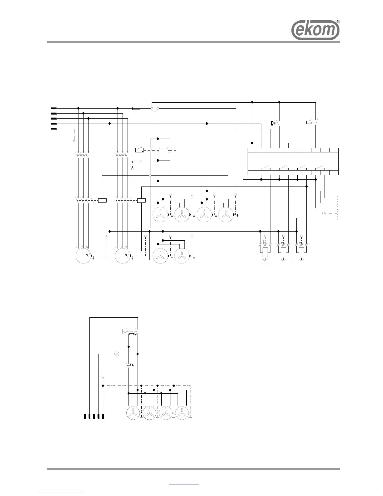
10. WIRING DIAGRAMS
DK50 2x4VR/110/M (MD)
DK50 2x4VR/110
M1,M2 Motor of compressor
F1,F2 Breaker
K3 PCB
Q1,Q1 Contactor
B2 Thermo switch
B1 Pressure switch
P1 Hour meter
E1 - E4 Fan of compressor
E5 – E6 Fan of cooler
M10,M20 Solenoid valve
X1 Terminal with fuse
F3 Fuse
X2 Connector
Page 17
DK50 2x4VR/110
10/2016 - 17 - NP-DK50 2x4VR110-12_10-2016
3/N/PE ~ 400/230 V 50..60 Hz
MAINS TN-S [TN-C-S]
ELECTRIC OBJECT 1ST.CAT
TYPE B
2
1
4
3
5
21436504
03
A1
A2
-Q11
M
6
21436504
03
A1
A2
-Q12
M
p >
40°C
-B1
-B2
-E1
-E2
PE
PE
-E3
-E4
PE
Q2Q1
-K1
Q3 Q4
L
N
I1 I2
I3
I4 I5 I6
I7
I8
1
2
1
2
12
1
2
-B4
-M12 -M10
-M11
p >
-B3
12
11
-F1
X1:2
PE
PE
3
~
3
~
PE PE PE
L1
L2
L3
N
F3 /1.6A
-E5
-E6
PE
PE
-X1:1
PE
2
1
4
3
5
6
-F2
PE
PE
PE
I3 Ekom
I4 Flairmo
I5 Absolute Air & Gas
-M1
-M2
3
2
1
PE
N
-X2
PE
-F3
PE
N
L
-X3
-X1:3
Alarm
Podla zakaznika:
c)
Reg_A
Reg_B
0.5s_M2
c)
1/N/PE ~ 230V 50/60Hz
ELECTRIC OBJECT 1ST.CAT
TYPE B
1 N2 3PE
L
N
1
-E10
-E11
DK50 2x4VR/110/M(NDL)
S110-4VR
E10-E13 Fan of box
X10,X11 Connector
S10 Switch
P10 LED-SERVIS for NDL
M1,M2 Motor of compressor
F1,F2 Breaker
K3 PCB
Q11,Q12 Contactor
B2 Thermo switch
B1,B3 Pressure switch
E1 - E4 Fan of compressor
E5 – E8 Fan of cooler
M10,M20 Solenoid valve
M11,M12 Solenoid valve of dryer
K1 Control unit
X1 Terminal with fuse
B4 Reed switch
F3 Fuse
X2 Connector
Page 18
DK50 2x4VR/110
NP-DK50 2x4VR110-12_10-2016 - 18 - 10/2016
7
8
9
5
3
1
1
1
1
2
6
3
1
1
1
1
2
6
4
4
7
8
9
10
5
16
10
4
11
12
14
3
1
1
1
1
2
6
3
1
1
1
1
2
6
11
12
13
6
9
15
16
18
19
17
6
6
7
8
9
5
11
12
3
1
1
1
1
2
6
3
1
1
1
1
2
6
11
12
16
18
19
17
6
6
4
4
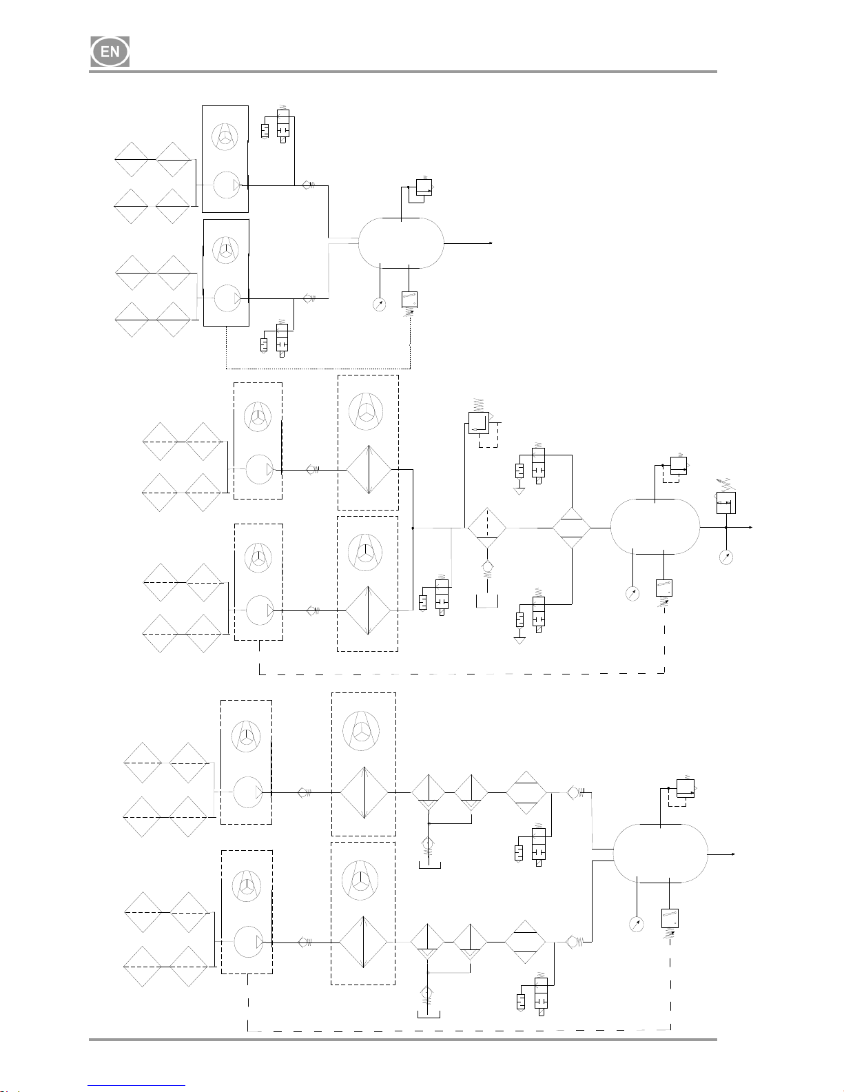
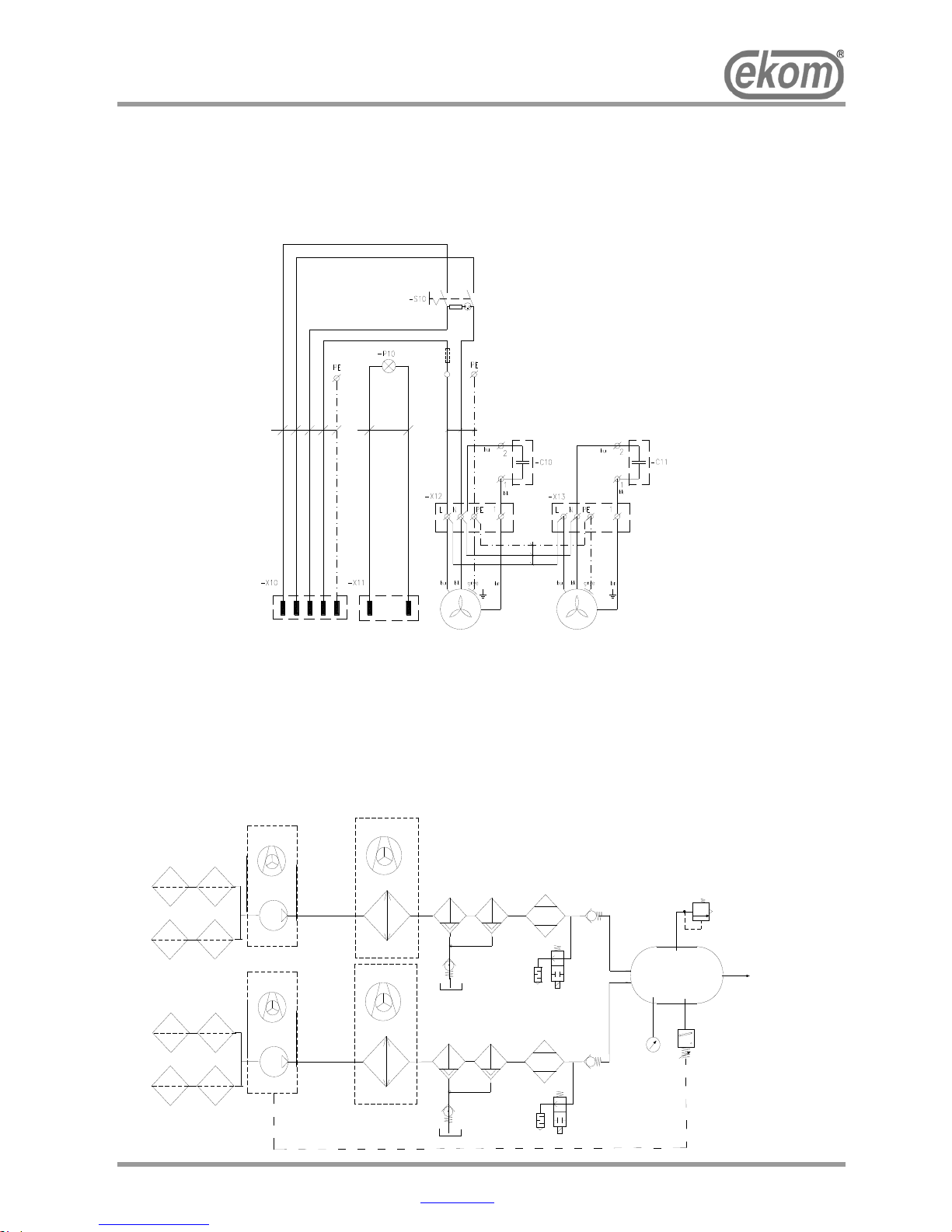
11. PNEUMATIC DIAGRAM
DK50 2x4VR/110
DK50 2x4VR/110/M (NDL)
DK50 2x4VR/110/M (MD)
1 Inlet filter
2 Compressor
3 Fan
4 Solenoid valve
5 Safety valve
6 Check valve
7 Pressure switch
8 Air tank
9 Pressure gauge
10 Dryer outlet solenoid valve
11 Cooler
12 Cooler fan
13 Condensate separator
14 Pressure relief valve
15 Pressure regulator
16 Dryer
17 Vessel
18 Filter
19 Mikrofilter
Page 19
DK50 2x4VR/110
10/2016 - 19 - NP-DK50 2x4VR110-12_10-2016
12. FIRST OPERATION
(Fig.17)
Make sure that all stabilizers used during transport were removed.
Check that all pressurized air line connections are secure.
Connect to the mains.
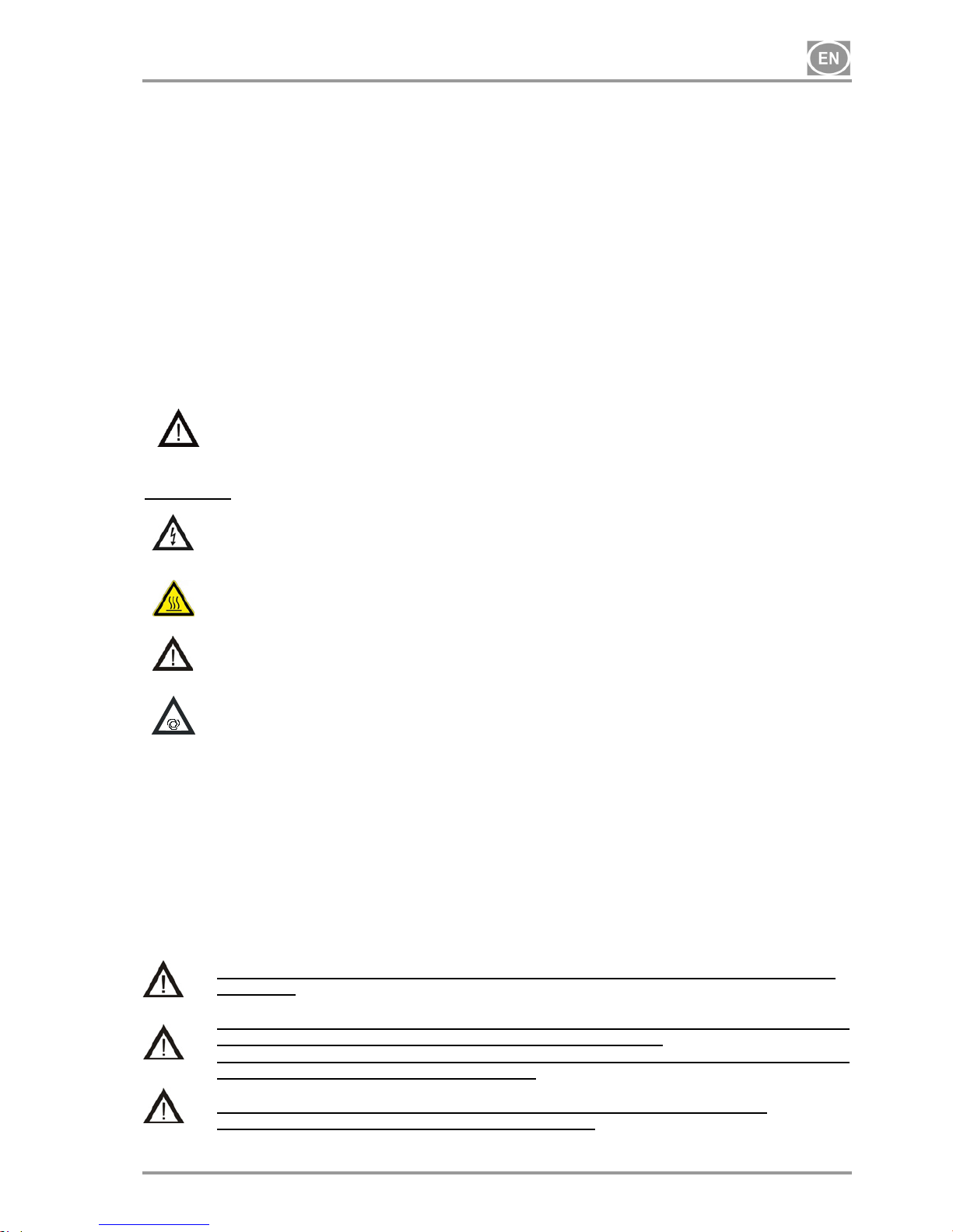
Start compressor at pressure switch (2) by turning switch (3) to position “I.“
For cabinet-mounted compressors, turn the switch (28) in Fig. 4 on the front side of the equipment cabinet
into the "I" position; a lighted switch indicates the equipment is in operation.
Compressor - At first operation the air tank is pressurized until it reaches a preset level when the
compressor automatically switches off. As the air is used, the compressor works in automatic mode,
switched on or off by the pressure switch.
Compressor with dryer – Compressor operation is the same and the moisture from the compressed air is
removed as it passes through the dryer.
For NDL - expanding regeneration air is vented out of the noise muffler on the dryer, which is audible as a
short hiss when the compressor stops or when the dryer chambers switch when the compressor is running.
The compressor is not equipped with an emergency power supply.
OPERATION
In case of emergency, disconnect the compressor from the mains (pull out the mains
plug).
The compressor has hot surfaces.
Burns or fire may result if contact is made.
During prolonged operation of the compressor, the temperature in the box may increase
to over 40°C. At this point the cooling fan automatically switches on. After cooling the
space to under 32°C, the ventilator switches off.
Automatic start: when pressure in the tank drops to the pressure switch’s lower limit
level, the compressor automatically switches on. The compressor automatically
switches off after reaching the pressure switch’s upper limit level.
Compressor with dryer
A correct function of the drier depends on the compressor’s operation and no attendance is required. The
pressure vessel need not be sludged, because the pressure air entering the air chamber is already dried.
- It is forbidden to alter the working pressures of pressure switch set by manufacturer. The operation
of the compressor at working pressure lower than the switching pressure demonstrates the overload
of the compressor (high air consumption) by the appliance, leakages in pneumatic distributions,
failure of aggregate or drier.
- Prior connecting drier to air chamber, that was used with compressor without drier, it is necessary to
clean interior surface of air chamber and perfectly remove condensed liquid. Then interconnect
electric part of drier with compressor according to wiring diagram in accord with valid regional
regulations.
Required drying performance can only be achieved when following the defined operating
conditions!
Drying performance will decline and the achieved dew point will drop if the dryer is
operated at any pressure below the minimum working pressure!
Dryer operation at a pressure of 0.5 Bar below the minimum working pressure can lower
the dew point at the outlet by more than 10°C!
The dryer will be irrevocably damaged and need replacement if operated at any
temperature above the maximum working temperature
Page 20
DK50 2x4VR/110
NP-DK50 2x4VR110-12_10-2016 - 20 - 10/2016
13. SWITCHING THE COMPRESSOR ON
(Fig.17)
Switch on the compressor at the pressure switch (2) by turning the
knob (3) to position “I.” (for compressor in the box switch (28) Fig.4), on
the front part of the compressor box), The compressor sends
pressurized air to the air tank. As the compressed air is used, the
pressure in the air nozzle drops to a preset level, the compressor
switches on and the air nozzle files with compressed air. After
reaching the cutoff pressure the compressor turns off automatically and
the cycle is repeated. Check the value of switching-on and switchingoff pressure on pressure gauge. The values may be within a tolerance
of 10%. Air pressure in air chamber must not exceed maximal
permitted operation pressure..
Never tamper with the pressure switch (2). Adjustments are not allowed. The pressure
switch (2) has been set by the manufacturer and further setting of switching on and off
pressure may be carried out only by a qualified expert trained by the manufacturer.
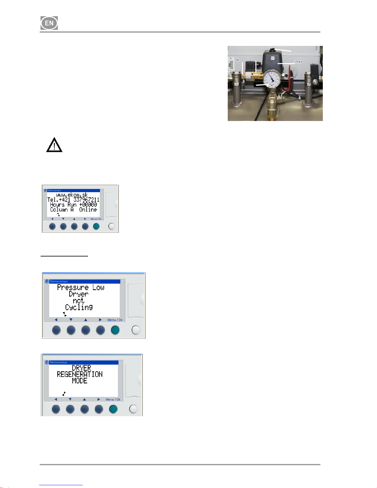
CONTROL PANEL SCREENS FOR THE NDL DRYER
-Supplier
-Supplier contact
-Operating hours
-Chamber A (B) in operation
Status messages
- Low pressure
a) From compressor start-up until pressure reaches 5.5 bar
b) During operation if pressure drops below 5.1 bar
- 24-hour regeneration mode
Dryer regeneration for 10 minutes is automatically switched
on after 24 hours of compressor operation.
Fi
g
.17
3
5
2
4
1
Page 21
DK50 2x4VR/110
10/2016 - 21 - NP-DK50 2x4VR110-12_10-2016
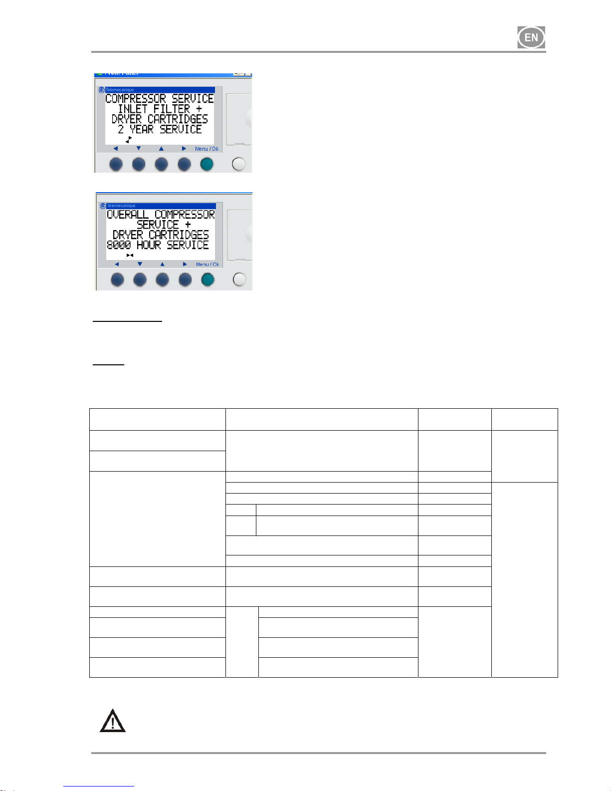
- 2 year maintenance
Calculated when equipment is switched on
- 8,000 hour maintenance
Calculated using the number of operating hours
MAINTENANCE
14. MAINTENANCE SCHEDULE
Notice!
The operating entity is obliged to ensure that all tests of the equipment are carried out repeatedly at
least once within every 24 months (EN 62353) or in intervals as specified by the applicable national
legal regulations. A report must be prepared on the results of the tests (e.g.: according to EN 62353,
Annex G), including the measurement methods used.
Time interval Maintenance that must be performed Chapter
Performed
by
1 x day
Emptying condensate
At high air humidity
Compressors without air dyers
Compressors with air dryers
15.2
User
1x per week
1x per week - check function
Once annually
Equipment cleaning
15.1
Check of dryer function
15.3
Qualified
technician
Safety valve check
15.4
NDL Replace float in water separator
15.6
MD
Replace filter and micro-filter
elements
15.7
15.8
Check tightness of joints
and overall inspection of the equipment
Maintenance
documentation
• Clean the cooler ribs and the fan
15.10
1 x every 2 years
Conduct "repeated test"
pursuant to EN 62353
14
1 x every 2 years or after 5000
hours
Replace inlet filter and pre-filte
r
15.5
NDL Replacement maintenance kit - dryer
8,000 hours (or 2 years) Replace media in both dryer cylinders
and seals.
15.9
16,000 hours (or 4 years) Replace media in both dryer cylinders
and seals.
24,000 hours (or 6 years) Replace media in both dryer cylinders,
seals and all valves.
15. MAINTENANCE
Repair work beyond normal maintenance can be performed only by qualified personnel or
the manufacturer’s representative.
Use only spareparts and accessories approved by the manufacturer.
Page 22
DK50 2x4VR/110
NP-DK50 2x4VR110-12_10-2016 - 22 - 10/2016
Fig.18
Prior to any maintenance or repair work, switch off the compressor and disconnect it from
the mains (pull out the mains plug).
TO ENSURE THAT THE COMPRESSOR WORKS CORRECTLY, PERFORM THE FOLLOWING
MAINTENANCE TASKS AT REGULAR INTERVALS (CHAPTER 14).:
THE CABINET MUST BE OPENED ON CABINET-MOUNTED COMPRESSORSBEFORE
CONDUCTING THE FOLLOWING CHECKS.
15.1. Equipment cleaning
The equipment, in particular the cooling fan must be kept clean to ensure the long-term efficiency of the
cooler – the cooling fins must be cleaned occasionally to remove any dust.
15.2. Condensation drain valve
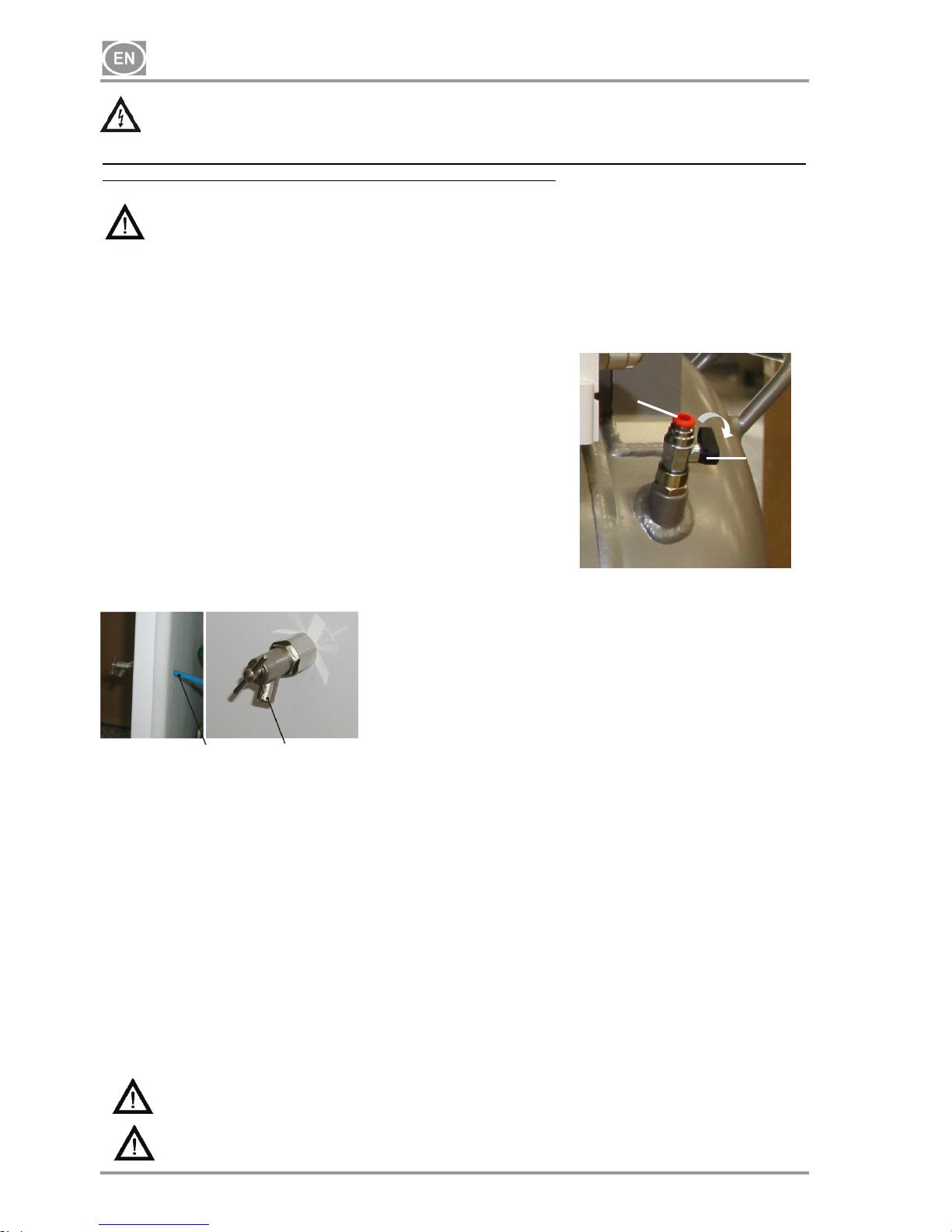
Compressors (Fig.18)
Switch off the compressor at the mains. Reduce air pressure in the
appliance to max. 1 bar by releasing air via a connected device.
Install the hose (062000492-000) provided with the standard product into
the valve (1) and drain condensate from the tank into the vessel by
opening the drain valve (1). Wait until all condensate is drained from the
pressure tank. Then close the drain valve (1), remove the hose by
compressing the plastic ring (2) and pulling it out of the valve.
Cabinet model compressors
Compressors with air dryer
In the case of a regular operation condensate is automatically excreted via air dryer and it is entrapped in a
bottle. Take out the bottle from a holder, release cap and pour out the condensate.
15.3. Check of dryer function
Check for proper dryer function by opening the vent valve. No condensate should leak out. Seek
professional assistance if condensate appears during such venting!
15.4. Safety valve check
(Fig.17)
When the compressor is operated for the first time, make sure that the safety valve is working properly. Turn
screw (4) of safety valve (1) several rotations to the left until the safety valve releases air. Let the safety
valve blow out for only a few seconds. Turn screw (4) to the right until it seats, closing the valve.
The safety valve must never be used for depressurizing the air tank. It could damage the
safety valve. The valve is set to the maximum permitted pressure by the manufacturer.
Adjustments are not permitted.
Warning! Compressed air can be dangerous. Wear eye protection when blowing air out.
1
2
38 37
Page 23
DK50 2x4VR/110
10/2016 - 23 - NP-DK50 2x4VR110-12_10-2016
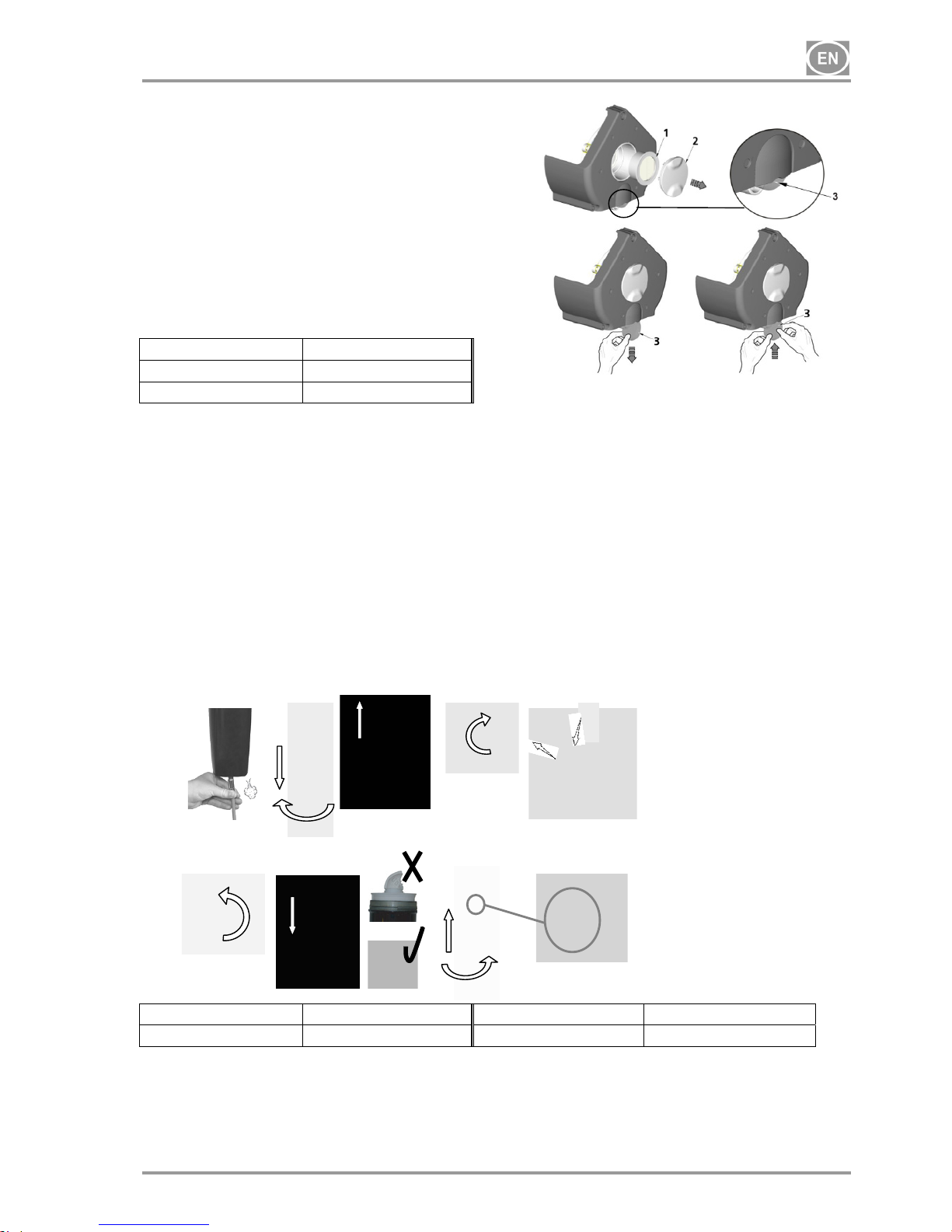
15.5. Replacement of the inlet filter and prefilter
(Fig.19)
At the lid of the compressors crankcase is an
Inlet filter (1) and prefilter (3).
Replacing of the inlet filter:
Hand pull the rubber stopper (2).
Remove used and dirty filter.
Input new filter and set rubber stopper.
Replacing of the prefilter:
Hand pull prefilter (3).
Replace old prefilter with new
Order number
Input filter
025200139
Prefilter
025200150
15.6. Replace float in water separator
(Fig.20)
During regular operation of drier is necessary to change the float in the water separator.
A) Release pressure.
B) Dismount separator container.
C) Pull out condenser separator
D) Release nut of the float placed in the bottom part of the container.
E) Pull out worn float of the separator and replace it for the new one.
F) Secure the float with the nut in bottom part of the container.
G) Place the condenser separator back as shown in the picture.
H) Container of the separator insert back and screw in.
I) The container is definitely secured in the point of the symbol.
Fig.20
Water separator Order number Float Order number
WS010BBFX 025200119 EF1 025200146
Fig.19
A
B
C
D
E
F
G
H
I
Page 24
DK50 2x4VR/110
NP-DK50 2x4VR110-12_10-2016 - 24 - 10/2016
3
Fi
g
. 22
1
2
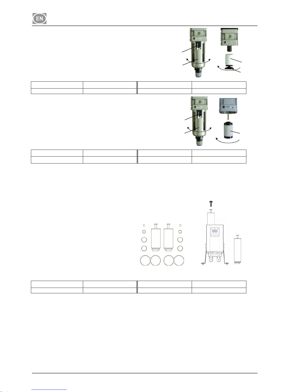
15.7. Replace the filter element
(Fig. 21)
Release the catch (1) on the filter vessel by pulling down.
Rotate the vessel (2) and remove.
Unscrew the filter retainer (3).
Replace the filter element (4) and reinstall the filter retainer.
Reinstall the filter vessel and rotate to secure against the catch.
Filter Order number Filter element Order number
AF40-F03C-6-A-PU 025200288-000
AF 40P-060S 5 m
025200079-000
15.8. Replacing the micro-filter element
(Fig. 22)
Release the catch (1) on the micro-filter vessel by pulling down.
Rotate the vessel (2) and remove.
Remove the filter (3).
Install the new filter element.
Reinstall the filter vessel and rotate to secure against the catch.
Micro-filter Order number Filter element Order number
AFM40-F03C-6-A-PU 025200289-000
AFM 40P-060AS 5 m
025200080-000
15.9. NDL dryer maintenance kit replacement
Before starting any work, disconnect the equipment from all power sources and vent the
air tank to zero
Repair work beyond normal maintenance can only be performed by qualified personnel or
the manufacturer’s representative.
The maintenance kit contains: Cartridge with drying media,
gaskets and valves depending on maintenance interval.
An indicator indicates maintenance interval :
- on the display - Zelio Logic
- on the cabinet
Dryer Order number Dryer service kit Order number
NDL-60 035900116 NDK-30
15.10. Clean the cooler ribs and the fan
For permanently high efficiency, it is necessary to maintain the whole equipment and especially the cooler´s
fan and the cooler itself clean – 1x year suck or blow settled dust out with compressed air from the surface of
the cooling ribs and the fan.
Fig.23-A: Spare parts Fig.23-B: Dryer cartridge
1
2
4
3
Fi
g
. 21
Page 25
DK50 2x4VR/110
10/2016 - 25 - NP-DK50 2x4VR110-12_10-2016
16. STORAGE
If the compressor will not be used for a prolonged time period, drain any condensate from the air tank. Then
turn on the compressor for 10 minutes, keeping the drain valve open (1) (Fig.18). Switch off the compressor
by switch (3) at pressure switch (2) (Fig.17), close the drain valve and disconnect the appliance from the
mains.
17. DISPOSING OF THE APPLIANCE
• Disconnect the appliance from the mains.
• Release air pressure in the pressure tank by opening the drain valve (1) (Fig.18).
• The components of the product are non-toxic.
• Dispose of the appliance following all environmental regulations.
18. REPAIR SERVICE
Guaranteed and post-guarantee repairs must be done by the manufacturer, its authorized representative, or
service personnel approved by the supplier.
The manufacturer reserves the right to make changes to the appliance without notice. Any changes made
will not affect the functional properties of the appliance.
19. SOLVING PROBLEMS
Caution! Before proceeding, depressurize the air tank to zero and disconnect the
appliance from the mains.
The internal surfaces of the air tank must be cleaned and all condensed liquid must be removed after a dryer
failure.
Check the dew point of the air leaving the air tank (see Chapter 5 - Technical Data) in order to protect
connected equipment from damage!
Page 26
DK50 2x4VR/110
NP-DK50 2x4VR110-12_10-2016 - 26 - 10/2016
Troubleshooting can be performed only by qualified personnel.
FAILURE POSSIBLE CAUSE REMEDY
Compressor does not
start
No voltage in pressure switch Check voltage in socket
Check fuse – replace faulty one
Loosen terminal – tighten it
Check power cord – replace faulty one
Disconnected winding of motor, damaged thermal
protection
Faulty capacitor
Seizure of piston or another rotary part Pressure switch
does not switch on
Replace motor or re-wind it
Replace capacitor
Replace damaged parts
Check the function of pressure switch
Compressor often
switches on
Air leak in pneumatic distribution system
Leaking check valve
Greater volume of condensed liquid in pressure vessel
Check pneumatic distribution system – seal loose joint
Clean valve, replace seals, replace valve
Drain condensed liquid
Prolonged running of
compressor
Air leak in pneumatic distribution system
Worn piston ring
Contaminated input filter and prefilter
Dirty filter in the dryer
Defective solenoid valve
Check pneumatic distribution system – seal loose joint
Replace worn piston ring
Replace contaminated filters with the new ones
Change the outlet filter and inspect dessicant
Repair or change the valve
Compressor is noisy
(knocking, metal noises)
Damaged bearing of piston, piston rod, motor bearing
Loose or cracked spring
Replace damaged bearing
Replace damaged spring
Membrane dryer
Dryer doesn´t dry
(condensed water in the
tank)
inoperative cooler ventilator replace ventilator ,check supply of electric energy
Damaged dryer Replace dryer
Dirty automatic condensate drain on filters clean / replace
Dirty filter and micro-filter elements Replace old elements with new elements
NDL Dryer
Decreased dew point
performance
1. Insufficient pressure at inlet
2. Electrical failure
3. Damp or contaminated dryer media
4. Excessively hi
gh air consumption
5. Excessive intlet air temper
atur
e
6. Insufficient clean air
7. Exhaust silencer blocked
1. Inlet pressure
m
ust be at least 4 Bar. If this is not the
case, adjust and set the inlet pressure.
2. Ensure the eq
uipment is switched on and the dryer'
s
front panel is lit, check for proper
dryer cycle.
3. Remove the s
ource of the contamination. Replac
e
the cartridges –
do not reuse.
4. Ensure dryer performance matches required air
demand.
5. Check technical specifications.
6. Cancel incorrect setti
ngs and contact a service
technician – adjust settings.
7. Contact a serv
ice technician.
Dryer cycle failure 8. Controller malfunction
9. Lamp is not lit
10. Insufficient inlet pressure
11. Venting malfunction during regeneration
12. Outp
ut flow halted
8. Check to ensu
re controller has power, check the
display to ensure the solenoid valves are powered
in
regular c
yclical operation.
9. Check unit po
wer and fuses
10. Inlet pressure must be at least 4 Bar. If this is not
the case, adjust and set the inlet pressure.
11. If the solenoid valve has power and is
malfunctioning – replace the valve. The valve is
w
orking properly if a click can be heard at the outlet
when venting
12. Check the air flow
at the inlet.
Constant venting 13. Dryer run failure
14. Irregular air flow from exhaust
13. Switch off and restart the dryer. Check to see if the
dryer is under pressure before switching on – to ensure
the dryer can be started before starting operation.
14. Defective or
damaged valve, maintenance required
Page 27
m e d i c a l a i r
EKOM spol. s r.o. + 421 33 7967 255 Annex to NP DK50 2x4VR 110-5_02-2017
Priemyselná 5031/18 + 421 33 7967 223 112000224-000
SK - 921 01 PIEŠŤANY e-mail: [email protected]
2 / 11
DK50 2X4VR/110S/M - 4041021B6-003
TECHNICAL DATA
Replaced - not apply chapter 5 in NP DK50 2x4VR/110 - TECHNICAL DATA
DK50 2x4VR/110S/M
Rated voltage /
frequency
V / Hz
3x400/50
Compressor output at 6 bar with
dryer
Lit.min
-1
NDL
400
Maximum compressor current with dryer A
10.6
Motor output kW
2x2.2
Air tank capacity Lit.
110
Working pressure bar
6.0 – 8.0
Maximum operating pressure of safety
valve
bar
12.0
Noise L
pfA
[dB]
58
Mode of operation with dryer
Continuous S1
Dimensions
with dryer
W x L x H
mm
NDL
1550x795x1240
Weight
with dryer
kg
NDL
252
Air dryer performance
Pressure dew point
NDL °C
- 35
Configuration pursuant to EN 60 601-1
Type B, class I.
Page 28
m e d i c a l a i r
EKOM spol. s r.o. + 421 33 7967 255 Annex to NP DK50 2x4VR 110-5_02-2017
Priemyselná 5031/18 + 421 33 7967 223 112000224-000
SK - 921 01 PIEŠŤANY e-mail: [email protected]
3 / 11
2
1
4
3
5
21436504
03
A1
A2
Q11
M
6
21436504
03
A1
A2
Q12
M
p >
40°C
B1
B2
E1
E2
PE
PE
E3
E4
PE
Q2Q1
K1
Q3 Q4
L
N
I1 I2
I3
I4 I5 I6
I7
I8
1
212121
2
B4
M11
M12
EA
EB
M10
p >
B3
M12
12
11
F1
3/N/PE ~ 400 V 50 Hz
ELEKTRICKÁ SIE TN-S [TN-C-S]
ELEKTRICKÝ PREDMET TR. I
TYP B
X1:1
PE
PE
3
~
3
~
PE PE PE
L1
L2
L3
N
F3 /1.6A
E5
E6
PE
PE
X1:2
PE
2
1
4
3
5
6
F2
PE
PE
PE
M1
M2
1
2
3
PE
N
X2
PE
F3
X3
1/N/PE ~ 230V 50/60 Hz
ELEKTRIC OBJECT 1st. CAT
TYPE B
S10
B10
1
P10
X10
40°C
E11 E12 E13E10
N23PE
PE
WIRING DIAGRAM
M1,M2 Motor of compressor
Q11,Q12 Contactor
FA1,FA2 Breaker
B2 Thermo switch
B1,B3 Pressure switch
E1 - E4 Fan of compressor
E5 – E8 Fan of cooler
M12 Solenoid valve
M10,M11 Solenoid valve of dryer
K1 Control unit
X1 Terminal with fuse
B4 Reed switch
F3 Fuse
E10-E13 Fan of box
X2 Connector
X10 Plug
S10 Switch
P10 LED-SERVIS for NDL
B10 Cabinet temperature switch
Page 29
m e d i c a l a i r
EKOM spol. s r.o. + 421 33 7967 255 Annex to NP DK50 2x4VR 110-5_02-2017
Priemyselná 5031/18 + 421 33 7967 223 112000224-000
SK - 921 01 PIEŠŤANY e-mail: [email protected]
6 / 11
1
GN
LED / AMB
N23PE
bn bu bk gy
bu
L
N
1/N/PE ~ 230 V 50 Hz
ELEKTRICKÝ PREDMET TR. I
TYP B
1
bn
-E10
-E11
16
18
19
17
6
6
7
8
9
5
11
12
3
1
1
1
1
2
3
1
1
1
1
2
11
12
16
18
19
17
6
6
4
4
WIRING DIAGRAM
For compressor box
PNEUMATIC DIAGRAM
1 Inlet filter 11 Cooler
2 Compressor 12 Cooler fan
3 Fan 16 Dryer
4 Solenoid valve
5 Safety valve
6 Check valve
7 Pressure switch
8 Air tank
9 Pressure gauge
E10-E13 Fan of box
X10,X11 Connector
S10 Switch
P10 LED-SERVIS for version with NDL dryer
C10, C11 Capacitor
Page 30

DK50 2X4VIIO
@omJ
 Loading...