

EKOM DK-50 2x2V/110 User Manual

DK50 2x2V/110
CONTENTS
IMPORTANT INFORMATION ................................................................................................................. 2
1. CONFORMITY WITH THE REQUIREMENTS OF EUROPEAN UNION DIRECTIVES ............ 2
2. INTENDED USE ......................................................................................................................... 2
3. CONTRAINDICATIONS AND SIDE-EFFECTS .......................................................................... 2
4. WARNINGS AND SYMBOLS ..................................................................................................... 2
5. WARNINGS ................................................................................................................................ 3
6. STORAGE AND TRANSPORT .................................................................................................. 5
7. TECHNICAL DATA ..................................................................................................................... 6
8. PRODUCT DESCRIPTION ........................................................................................................ 9
9. PRODUCT FUNCTIONALITY .................................................................................................. 11
10.PNEUMATIC DIAGRAM ........................................................................................................... 15
INSTALLATION .................................................................................................................................... 17
11.CONDITIONS FOR USE .......................................................................................................... 17
12.PLACEMENT OF THE COMPRESSOR .................................................................................. 18
13.PNEUMATIC CONNECTIONS ................................................................................................. 20
14.ELECTRICAL CONNECTIONS ................................................................................................ 21
15.CONNECTION DIAGRAM ........................................................................................................ 23
OPERATION ......................................................................................................................................... 26
16.COMMISSIONING .................................................................................................................... 26
17.SWITCHING THE COMPRESSOR ON ................................................................................... 27
18.COMPRESSOR SHUT-DOWN ................................................................................................ 27
MAINTENANCE .................................................................................................................................... 28
19.DEVICE MAINTENANCE ......................................................................................................... 28
TROUBLESHOOTING .......................................................................................................................... 34
20.REPAIR SERVICE .................................................................................................................... 35
21.STORAGE ................................................................................................................................ 35
22.DISPOSAL OF THE DEVICE ................................................................................................... 35
ANNEX ................................................................................................................................................ 142
23.INSTALLATION RECORD ...................................................................................................... 142
10/2018 - 1 - NP-DK50 2x2V 110-2_10-2018-MD A
DK50 2x2V/110
IMPORTANT INFORMATION
1. CONFORMITY WITH THE REQUIREMENTS OF EUROPEAN UNION DIRECTIVES
This product conforms to the requirements of the Medical Device Directive (93/42/EEC) and the
Machinery Directive (2006/42/EC), and is safe for the intended use if all safety instructions are
followed.
2. INTENDED USE
The compressor is used as a source of clean, oil-free compressed air to power dental unit,
instruments, and devices in laboratories where the parameters and properties of the compressed
air are suitable for the specific application.
Compressed air supplied by the compressor is unsuitable for use with artificial lung
ventilation devices without further filtration
Any other use of the product beyond its intended use is considered an incorrect use. The
manufacturer is not liable for any damages or injuries resulting from the incorrect use.
3. CONTRAINDICATIONS AND SIDE-EFFECTS
There are no contraindications or side-effects known.
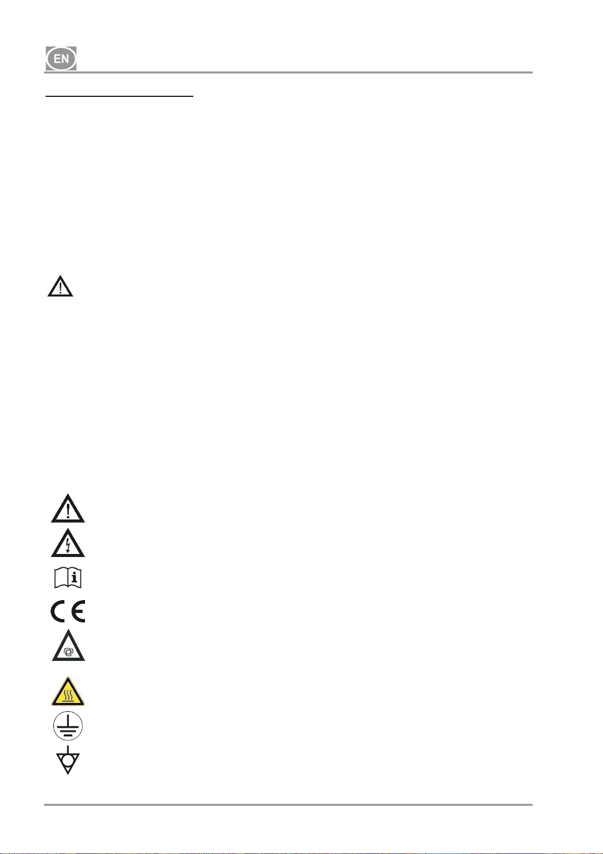
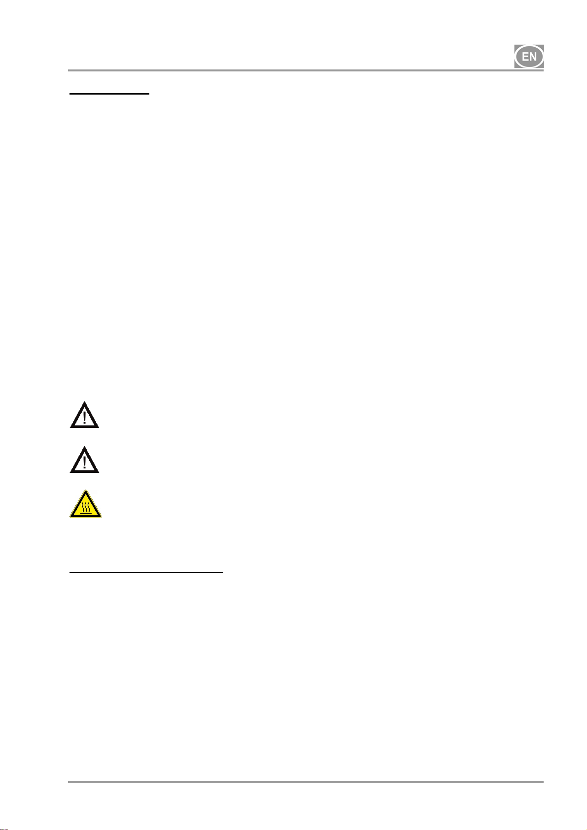
4. WARNINGS AND SYMBOLS
The following symbols are used in the user manual, device and its packaging to denote important
details and information:
General warnings
Danger, electric shock hazard
Read the user manual!
CE-marking
Compressor is controlled automatically and may start without warning
Caution! Hot surface
Ground connection
Terminal for ground connection
NP-DK50 2x2V 110-2_10-2018-MD A - 2 - 10/2018
DK50 2x2V/110
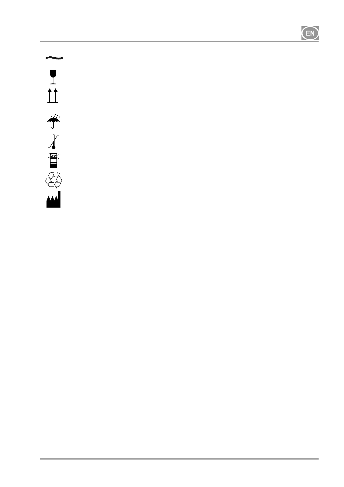
Alternating current
Handling mark on package – FRAGILE
Handling mark on package – THIS SIDE UP
Handling mark on package – KEEP DRY
Handling mark on package – TEMPERATURE LIMITATIONS
Handling mark on package – LIMITED STACKING
Mark on package – RECYCLABLE MATERIAL
Manufacturer
5. WARNINGS
The product is designed and manufactured to be safe for the user and the surrounding
environment when used in the defined manner. Keep the following warnings in mind.
5.1. General warnings
READTHE USER MANUAL CAREFULLY BEFORE USING THE DEVICE AND KEEPIT FOR
FUTURE USE!
The user manual supports the correct installation, operation and maintenance of the product.
Careful review of this manual will provide the information necessary for the correct operation of
the product for its intended use.
Original packaging should be retained for the return of the device. Only the original packaging
ensures protection of the device during transport. If it is necessary to return the product during
the warranty period, the manufacturer is not liable for damages caused by improper packaging.
This warranty does not cover damages originating from the use of accessories other than those
specified or recommended by the manufacturer.
The manufacturer only guarantees the safety, reliability and function of the device if:
- installation, new settings, changes, expansion, and repairs are performed by the
manufacturer or an organisation authorised by the manufacturer.
- the product is used pursuant to the user manual.
The user manual corresponds to the configuration of the product and its compliance with the
applicable safety and technical standards at the time of printing. The manufacturer reserves all
rights for the protection of its configuration, methods and names.
10/2018 - 3 - NP-DK50 2x2V 110-2_10-2018-MD A

DK50 2x2V/110
Translation of the user manual is performed in accordance with the best available knowledge.
The Slovak version is to be used in the event of any uncertainties.
5.2. General safety warnings
The manufacturer designed and manufactured the product to minimise all risks when used
correctly for the intended use. The manufacturer considers it its obligation to lay down the
following general safety precautions.
Use and operation of the product must comply with all laws and local regulations valid in the
place of use. The operator and user are responsible for following all the appropriate regulations
in the interests of performing work safely.
Only the use of original parts guarantees the safety of operating personnel and the flawless
operation of the product itself. Only the accessories and parts mentioned in the technical
documentation or expressly approved by the manufacturer should be used.
The operator must ensure that the device is functioning correctly and safely before every use.
The user must be familiar with the operation of the device.
Do not use the product in environments with a risk of explosion.
The user must inform the supplier immediately if any problem directly related to the operation of
the device occurs.
5.3. Safety warnings on protection from electric current
The device must only be connected to a properly installed, earthed socket.
Before the product is plugged in, ensure that the mains voltage and frequency stated on the
product are in compliance with thevalues of the mains.
Prior to putting the device into operation check for any damage to the connected pneumatic
lines and electrical wiring. Replace damaged pneumatic lines and electrical wiringsimmediately.
Immediately disconnect the product from the mains (remove power cord from the socket) in
hazardous situations or in the case of a technical malfunction.
During all repairs and maintenance, ensure that:
- the mains plug is removed from the power socket
- pressure is vented from the air tank and pipes
The product shall only be installed by a qualified technician.
NP-DK50 2x2V 110-2_10-2018-MD A - 4 - 10/2018
DK50 2x2V/110
6. STORAGE AND TRANSPORT
The compressor is shipped from the factory in a transport packaging. This protects the device from
damage during transport.
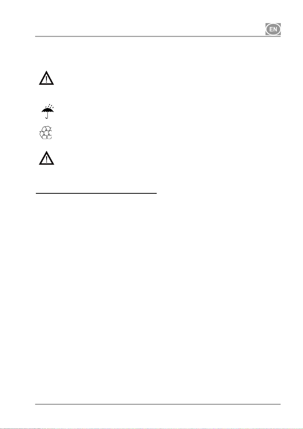
The original compressor packaging must be used for transport whenever
possible. Transport the compressor in an upright position, always secured with
transport fixation.
Protect the compressor from moisture, dirt and extreme temperatures during transport
and storage. Store the compressor in its original packaging in a warm, dry, and dustfree area. Do not store near any chemical substances.
Ambient conditions for storage and transport
Keep the packaging material, if possible. If not, please dispose of the packaging
material in an environmentally-friendly way. Packaging cardboard can be recycled with
old paper.
The compressor may only be transported when all air pressure has been vented.
Before moving or transporting the compressor, release all air pressure from the
tank and hoses and drain condensate from the air tank.
Products may only be stored and transported in vehicles that are free of any traces of volatile
chemicals under the following conditions:
Temperature: –25°C to +55°C, 24 h at up to +70°C
Relative humidity: 10% to 90% (non-condensing)
10/2018 - 5 - NP-DK50 2x2V 110-2_10-2018-MD A
1
DK50 2x2V/110
7. TECHNICAL DATA
Compressors are designed for dry and ventilated indoor environments with the following
conditions:
Temperature : +5°C to +40°C,
Max. relative humidity.: 70%,
Max. absolute humidity. 15 g/m
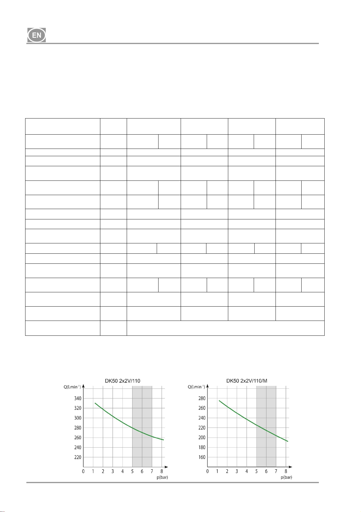
Tab.1
5 – 7 bar
Nominal voltage /
frequency (*)
Performance at 5 bar Lit.min
Working pressure (**) bar 5.0 – 7.0 5.0 – 7.0 5.0 – 7.0 5.0 – 7.0
Performance with KJF-2
at 5 bar
Max. current
Motor power
Air tank volume
Air quality – filtration
Maximum operating
pressure of safety valve
Noise level at 5 bar
Duty cycle
PDP - drying performance
at 7 bar
Time to fill air tank from 0
to 6 bar
Dimensions (net)
w x d x h
Net weight (****)
Classification under EN
60601-1
Notes:
(*) When ordering, state the version of the compressor
(**) For other range of pressure:consult with the supplier
(***) Weight of compressors with a KJF-2 unit _add 4 kg
(****) Information about the weight is for informative purposes only and applies to the product without any
additional accessories.
V / Hz
Lit.min
A
kW
Lit.
m
bar
LpfA [dB]
s
mm
kg
3
DK50
2x2V/110
230/50
3x400/50
-
280 280 225 225
-1
280 280 - -
230/60
115/60
16.1
5.6
2x1.2
2x1.2
2x1.2
2x1.1
110
DK50
2x2V/110S
230/50
3x400/50
16.5
6
2x1.2
2x1.2
230/60
115/60
2x1.2
2x1.1
DK50
2x2V/110/M
230/50
3x400/50
16.2
5.7
2x1.2
2x1.2
230/60
115/60
2x1.2
2x1.1
110 110 110
DK50
2x2V/110S/M
230/50
3x400/50
16.6
6.1
2x1.2
2x1.2
- - 0.3 0.3
9,0 9,0 9,0 9,0
73
55
73
56
100% 100% 100% 100%
- -
+3°C
+3°C
131 131 163 163
1085x490x815 1200x725x992 1085x625x815 1200x725x992
106 (***)
104 (***)
177 (***)
175 (***)
113
111
184
182
Class I.
230/60
115/60
2x1.2
2x1.1
NP-DK50 2x2V 110-2_10-2018-MD A - 6 - 10/2018
DK50 2x2V/110
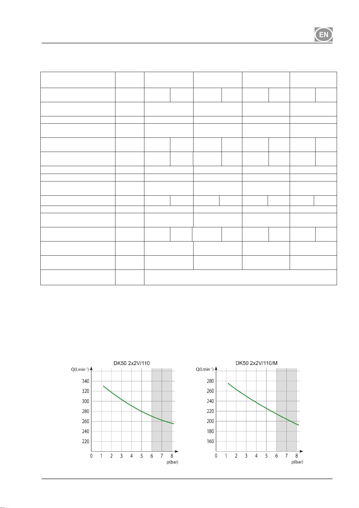
Tab. 2
6 – 8 bar
Nominal voltage /
frequency (*)
Performance
at 6 bar
V / Hz
Lit.min
-1
270 270 215 215
DK50
2x2V/110
230/50
3x400/50
230/60
115/60
Working pressure (**) bar 6.0 – 8.0 6.0 – 8.0 6.0 – 8.0 6.0 – 8.0
Performance with KJF-2
at 6 bar
Max. current A
Motor power kW
Air tank volume
Air quality – filtration
Maximum operating
pressure of safety valve
Noise level at 5 bar
-1
Lit.min
270 270 - -
16.7
5.8
2x1.2
2x1.2
Lit.
m
2x1.2
2x1.1
110
- - 0.3 0.3
bar 9.0 9.0 9.0 9.0
LpfA [dB]
73
Duty cycle 100% 100% 100% 100%
PDP drying performance
at 7 bar
Time to fill air tank from 0
to 7 bar
Dimensions (net)
w x d x h
Net weight (****) kg
Classification under
- -
s 159 159 198 198
mm 1085x490x815 1200x725x992 1085x625x815 1200x725x992
106 (***)
104 (***)
EN 60601-1
Notes:
(*) When ordering, state the version of the compressor
(**) Forother range of pressureconsult with supplier
(***) Weight of compressors with a KJF-2 unit _add 4 kg
(****) Information about the weight is for informative purposes only and applies to the product without any
additional accessories.
DK50
2x2V/110S
230/50
3x400/50
17.1
6.2
2x1.2
2x1.2
230/60
115/60
2x1.2
2x1.1
DK50
2x2V/110/M
230/50
3x400/50
16.8
5.9
2x1.2
2x1.2
230/60
115/60
2x1.2
2x1.1
110 110 110
55
73
+3°C
177 (***)
175 (***)
113
111
Class I.
DK50
2x2V/110S/M
230/50
3x400/50
17.2
6.3
2x1.2
2x1.2
56
+3°C
184
182
230/60
115/60
2x1.2
2x1.1
10/2018 - 7 - NP-DK50 2x2V 110-2_10-2018-MD A
DK50 2x2V/110
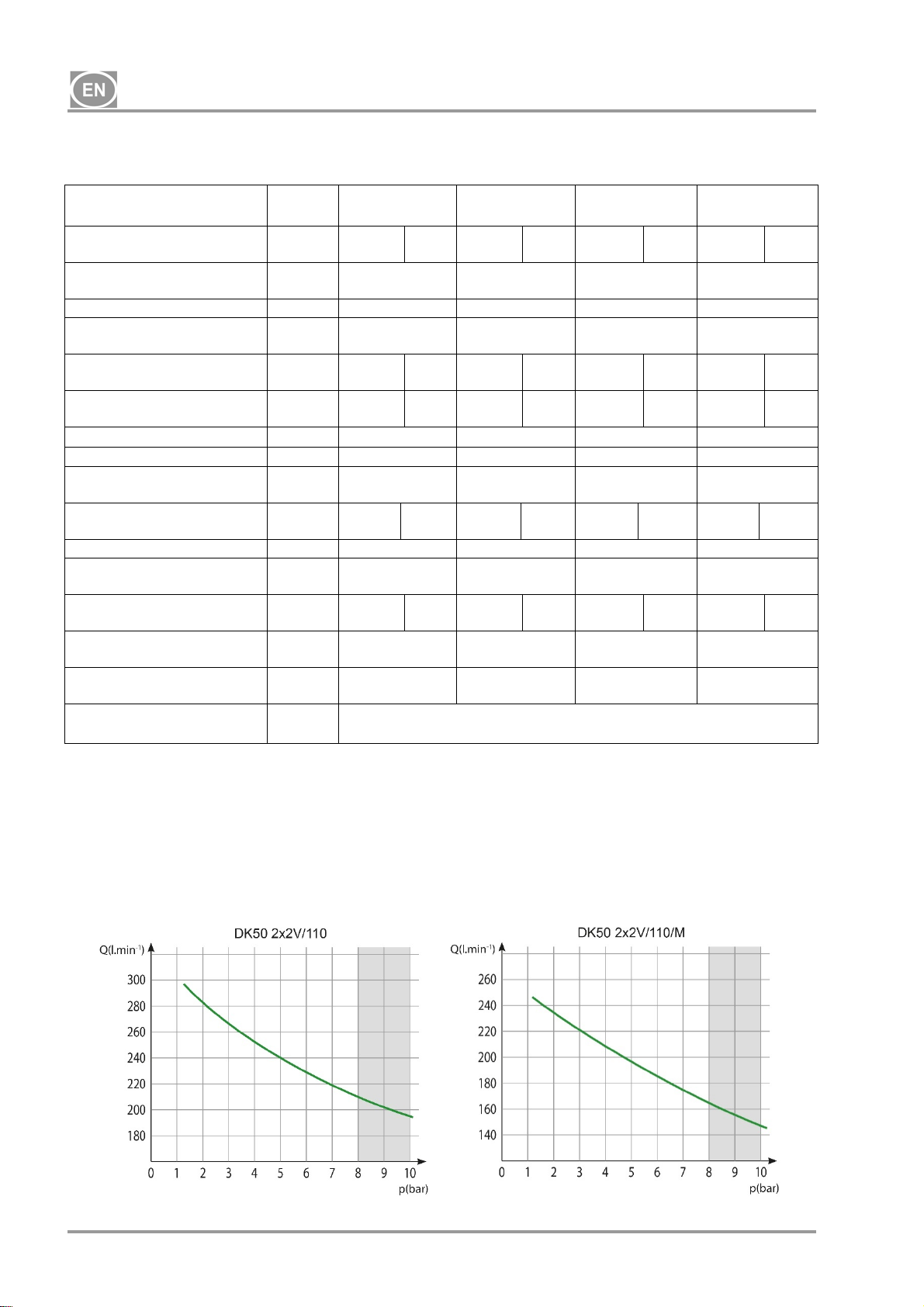
Tab. 3
8 – 10 bar
Nominal voltage /
frequency (*)
Performance
at 8 bar
V / Hz
Lit.min
-1
210 210 165 165
DK50
2x2V/110
230/50
3x400/50
230/60
115/60
Working pressure (**) bar 8.0 – 10.0 8.0 – 10.0 8.0 – 10.0 8.0 – 10.0
Performance with KJF-2
at 8 bar
Max. current A
Motor power kW
Air tank volume
Air quality – filtration
Maximum operating
pressure of safety valve
Noise level at 5 bar LpfA
-1
Lit.min
210 210 - -
16.5
6.2
2x1.2
2x1.2
Lit.
m
2x1.2
2x1.1
110
- - 0.3 0.3
bar 12.0 12.0 12.0 12.0
[dB]
73,0
Duty cycle 100% 100% 100% 100%
PDP drying performance at
7 bar
Time to fill air tank from 0 to
9 bar
Dimensions (net)
w x d x h
Net weight (****) kg
Classification under
- -
s 256 256
mm 1085x490x815 1200x725x992 1085x625x815 1200x725x992
110 (***)
108 (***)
EN 60601-1
Notes:
(*) When ordering, state the version of the compressor
(**) For otherrange of pressure consult with supplier
(***) Weight of compressors with a KJF-2 unit _add 4 kg
(****) Information about the weight is for informative purposes only and applies to the product without any
additional accessories.
DK50
2x2V/110S
230/50
3x400/50
16.9
6.6
2x1.2
2x1.2
230/60
115/60
2x1.2
2x1.1
DK50
2x2V/110/M
230/50
3x400/50
16.6
6.3
2x1.2
2x1.2
230/60
115/60
2x1.2
2x1.1
110 110 110
55
73
+3°C
181 (***)
179 (***)
117
115
Class I.
DK50
2x2V/110S/M
230/50
3x400/50
17.0
6.7
2x1.2
2x1.2
56
+3°C
188
186
230/60
115/60
2x1.2
2x1.1
NP-DK50 2x2V 110-2_10-2018-MD A - 8 - 10/2018
DK50 2x2V/110
7.1. Free air delivery (FAD) correction due to elevation
FAD correction table
Elevation [mamsl] 0 - 1500 1501 - 2500 2501 - 3500 3501 - 4500
FAD [l/min] FAD x 1 FAD x 0.8 FAD x 0.71 FAD x 0.60
FAD („Free Air Delivery“) output related to conditions:
Elevation: 0 MASL Temperature : 20°C
Atmospheric pressure : 101325 Pa Relative humidity : 0%
8. PRODUCT DESCRIPTION
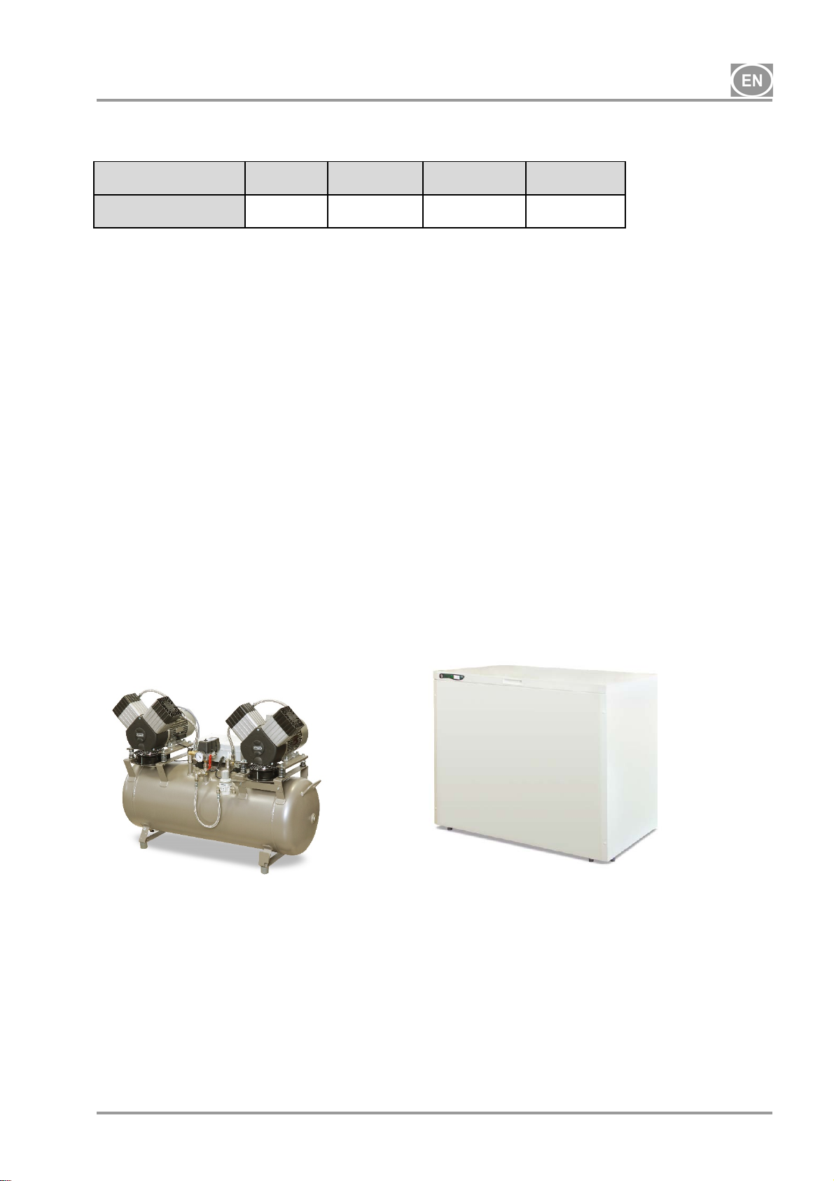
8.1. Variants
Compressor models are designed in the following variants:
DK50 2x2V/110 - Compressor for installation in areas where operations will not disturb the
surroundings.
DK50 2x2V/110/K - Compressor with a condensing and filter unit
DK50 2x2V/110/M - Compressor with a membrane air dryer
DK50 2x2V/110S - Compressor in a cabinet with efficient soundproofing
DK50 2x2V/110S/K - Compressor in a cabinet with a condensation and filtration unit
DK50 2x2V/110S/M - Compressor in a cabinet with an air dryer
Cabinet S110 - used to reduce the level of noise generated by the compressor.
S110
DK50 2x2V/110 DK50 2x2V/110S
10/2018 - 9 - NP-DK50 2x2V 110-2_10-2018-MD A
DK50 2x2V/110
8.2. Accessories
Accessoriesnot included in the standard order must be ordered separately!
8.2.1. Automatic condensate drain
The automatic condensate drain (AOK) automatically drains condensate from the compressor’s air
tank based on a pre-set time interval. The condensate drain (AOK) is a suitable accessory for
compressor models without dryers.
Type Use Kit article no.
AOK 12 DK50 2x2V/110 447000001-123
8.2.2. Regulator set
Compressors may be equipped with a regulator set on the compressed air outlet if specified. The
regulator sets are suitable accessories for all the compressors specified above.
Type Use Kit article no.
REG13
DK50 2x2V/110,
DK50 2x2V/110/M
447000001-096
8.2.3. Filters set
Compressors may be equipped with a filters set on the compressed air outlet if specified. The set
of filters may be equipped with a pressure regulator. Filters set are suitable accessories for all the
compressors specified above.
NOTE : If a higher level of air filtration is required, this specification must be agreed on with the
supplier and made clear in the order.
Type Use Level of filtration / µm /
FS 34FR DK50
FS 34M
FS 34MR
FS 34S
FS 34SR
FS 35S
FS 35SR
8.2.4. Condensation and filtration unit
The compressor may be additionally fitted with a condensation and filtration unit.
The KJF-2 ensure that the compressed air from the air tank is cooled in the cooler and the
condensate is captured in the filter and automatically separated from the pneumatic distribution
system. The compressed air is filtered at the same time.
Type Use Level of filtration / µm /
2x2V/110
DK50
2x2V/110/M
5 yes
5 + 0.3 no
5 + 0.3 yes
5 + 0.3 + 0.01 no
5 + 0.3 + 0.01 yes
0.3 + 0.01 no
0.3 + 0.01 yes
Pressure
regulator
Pressure
regulator
Kit article no.
447000001-097
447000001-098
447000001-099
447000001-100
447000001-101
447000001-102
447000001-103
Kit article no.
KJF-2 DK50 2x2V/110 5 no 450001021-001
8.2.5. Equipotential bonding socket
The socket allows an equipotential bonding. (Fig.12)
Type Use Article no.
POAG-KBT6-EC
FLEXI-S/POAG-HK6 034110083-000
NP-DK50 2x2V 110-2_10-2018-MD A - 10 - 10/2018
DK50 2x2V/110S
DK50 2x2V/110S/M
033400075-000
DK50 2x2V/110
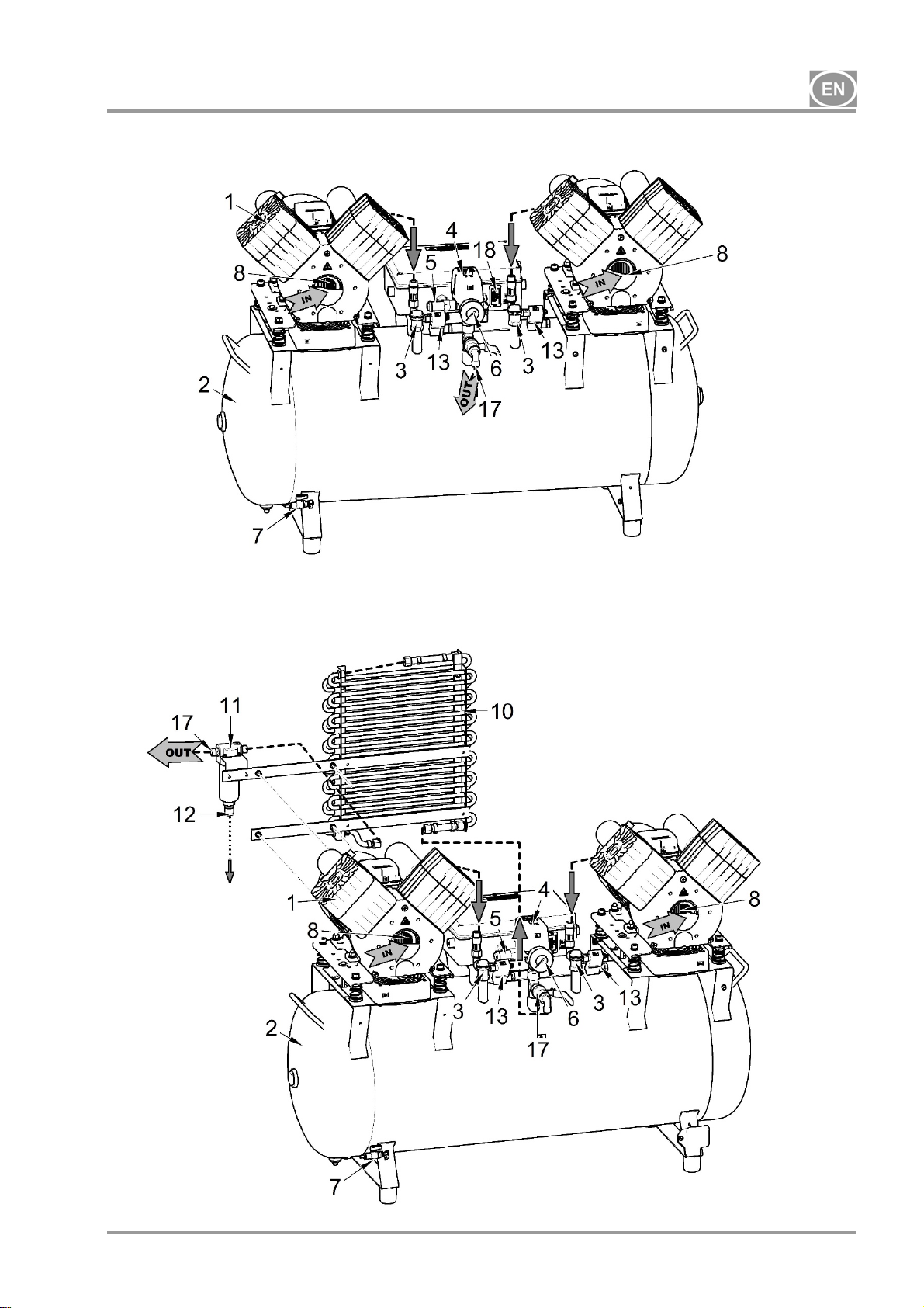
9. PRODUCT FUNCTIONALITY
Compressor (Fig. 2)
The air pump (1) draws in atmospheric air through an inlet filter (8) and compresses it through
a non-return valve (3) into an air tank (2) from which the device draws compressed air. If the
pressure in the air tank drops to the switch-on pressure, the pressure switch (4) turns on the
compressor and the compressor supplies compressed air into the air tank until it reaches the
switch-off pressure, when the compressor switches off. The pressure hose is vented through the
relief solenoid valve (13) once the air pumpis shut off. The safety valve (5) prevents the pressure
in the air tank from rising above the maximum allowed value. The drain valve (7) drains
condensate from the air tank. Compressed, oil-free filtered air is stored in the air tank ready for
use.
Condensate must be drained from the air tank at regular intervals (see Chapter 19.1).
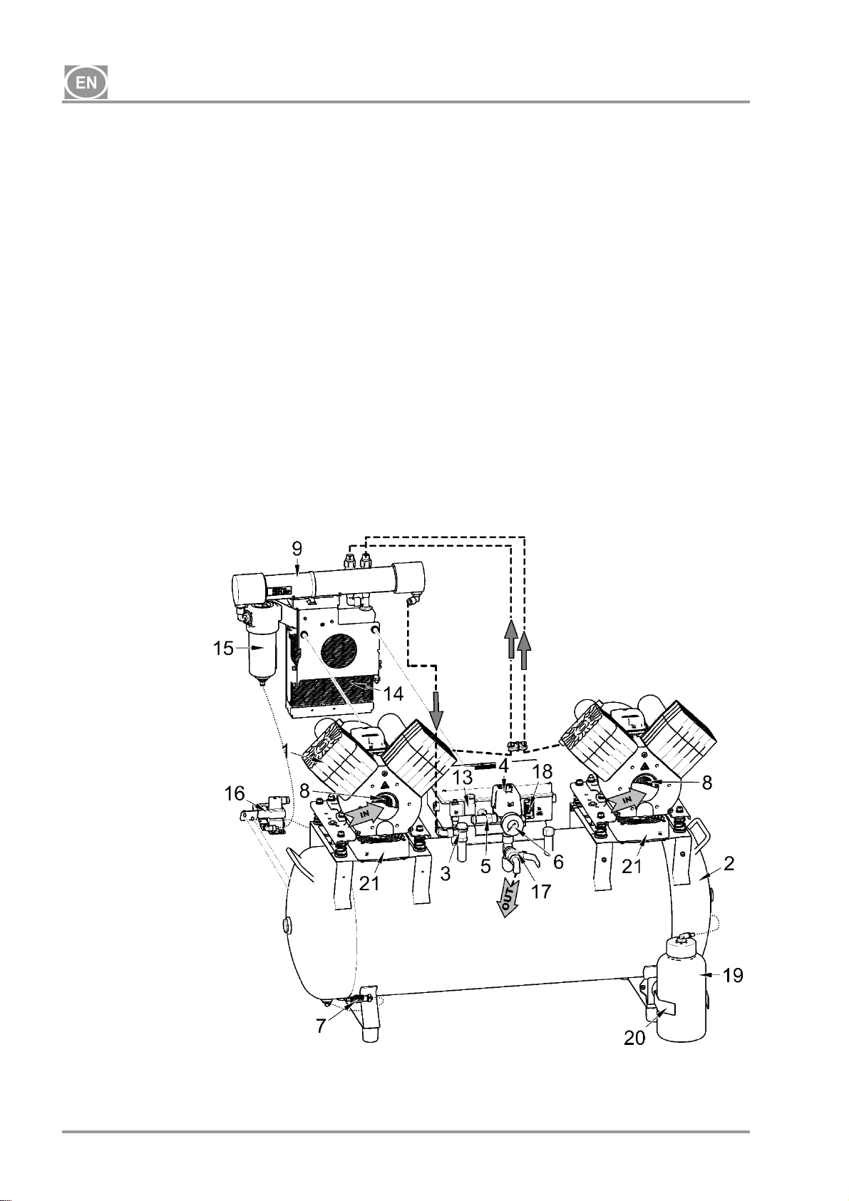
Compressor with membrane dryer (Fig. 1)
The air pump (1) draws in atmospheric air through an inlet filter (8) and compresses it, feeding it
through the coolers (14) and the filter (15) into the dryer (9) and the dry, clean air is then fed
through the non-return valve (3) into the air tank (2). A part of the air is released from the dryer
with the captured moisture, which is manifested as a light air stream along the body of the dryer
(9). Condensate from the filter is automatically drained at regular intervals into the collecting bottle
via the condensate drain solenoid valve (16). The dryer ensures continuous drying of the
compressed air. The drain valve (7) drains condensate from the air tank when drying performance
is checked. Compressed, oil-free filtered air is stored in the air tank ready for use.
The pressure vessel does not need to be drained.
Compressor with condensation and filtration unit(Fig. 3)
The air pump (1) draws in air through an inlet filter (8) and compresses it through a non-return
valve (3) into the air tank (2). Compressed air from the air tank flows through a cooler (10) that
cools the compressed air. The condensed moisture is trapped in the filter (11) and automatically
separates as condensate (12) into the collecting bottle. Compressed, oil-free filtered air is ready
for use.
Condensate must be drained from the air tank at regular intervals (see Chapter 19.1).
Compressor cabinet(Fig.4)
The soundproof cabinetprovides compact covering of the compressor, allowing sufficient
exchange of cooling air. With its design It can be placed in a dentist’s office as apart of furniture.
The fan under the air pump of a compressor provides cooling of compressor and it is in operation
at the same time with an engine of the compressor. After prolonged use the temperature in the
cabinet may rise above 40°C, causing the cooling fan blower to automatically turn on. After
cooling the cabinet area down to 32°C the fan blower turns off automatically.
Make sure that nothing impedes the free flow of air under and around the
compressor. Never cover the hot air outlet on the top back side of the cabinet.
If placing the compressor on a soft floor such as carpet, create space for
ventilation between the base and floor or the cabinet and floor, e.g. underpin the
footings with hard pads.
For 8-10 bar compressor models, an hourly meter is installed on the pressure switch.
10/2018 - 11 - NP-DK50 2x2V 110-2_10-2018-MD A
DK50 2x2V/110
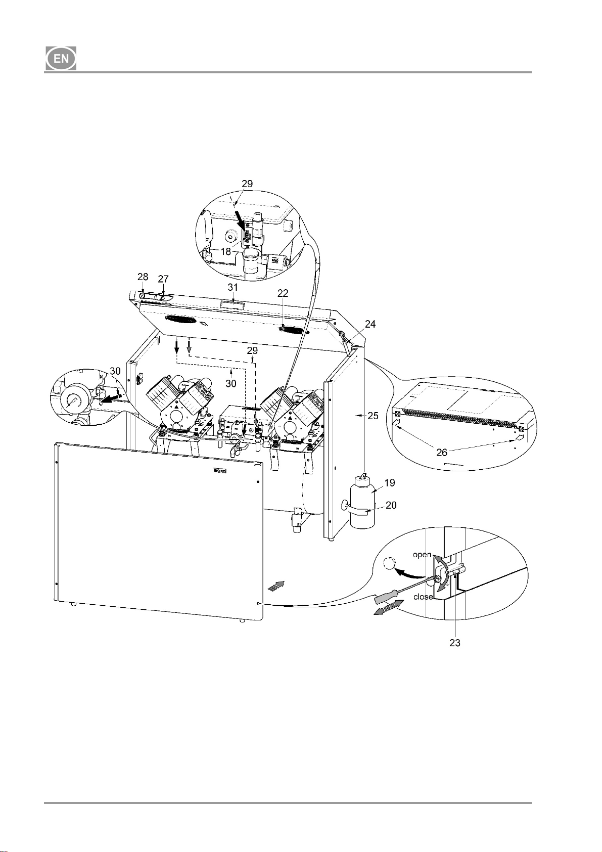
Description for Figures 1-4
1. Air pump
2. Air tank
3. Non-return valve
4. Pressure switch
5. Safety valve
6. Pressure gauge
7. Drain valve
8. Inlet filter
9. Dryer
10. KJF - cooler
11. Filter
12. Condensate outlet
13. Solenoid valve
14. Dryer cooler
15. Filter
16. Condensate drain solenoid
valve
17. Ball valve
Fig. 1 - Compressor with MD dryer
18. Socket
19. Bottle
20. Magnetic holder
21. Fan
22. Cabinet fan
23. M5 screw
24. Cabinet gas springs
25. Cabinet enclosure
26. Wall stop
27. Switch
28. Pressure gauge
29. Power cord
30. Pressure gauge hose
31. Handle S110
NP-DK50 2x2V 110-2_10-2018-MD A - 12 - 10/2018
DK50 2x2V/110
Fig. 2 - Compressor
Fig. 3 - Compressor with condensation and filtration unit
10/2018 - 13 - NP-DK50 2x2V 110-2_10-2018-MD A
DK50 2x2V/110
Fig. 4 - Cabinet
NP-DK50 2x2V 110-2_10-2018-MD A - 14 - 10/2018
DK50 2x2V/110
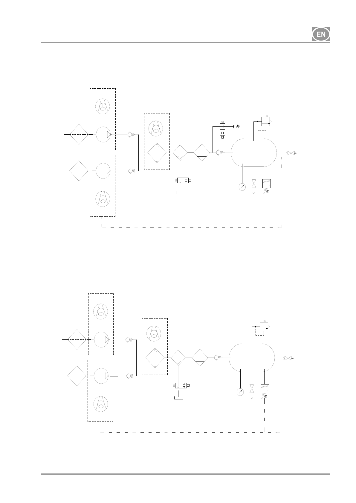
10. PNEUMATIC DIAGRAM
DK50 2x2V/110/M 230V
1
1
DK50 2x2V/110/M 400V
1
1
3
2
2
3
2
2
9
5
10
11
7
9
10
11
7
17
8
17
8
12
12
3
3
13
14
16
15
13
14
16
15
6
6
6
6
4
6
6
10/2018 - 15 - NP-DK50 2x2V 110-2_10-2018-MD A
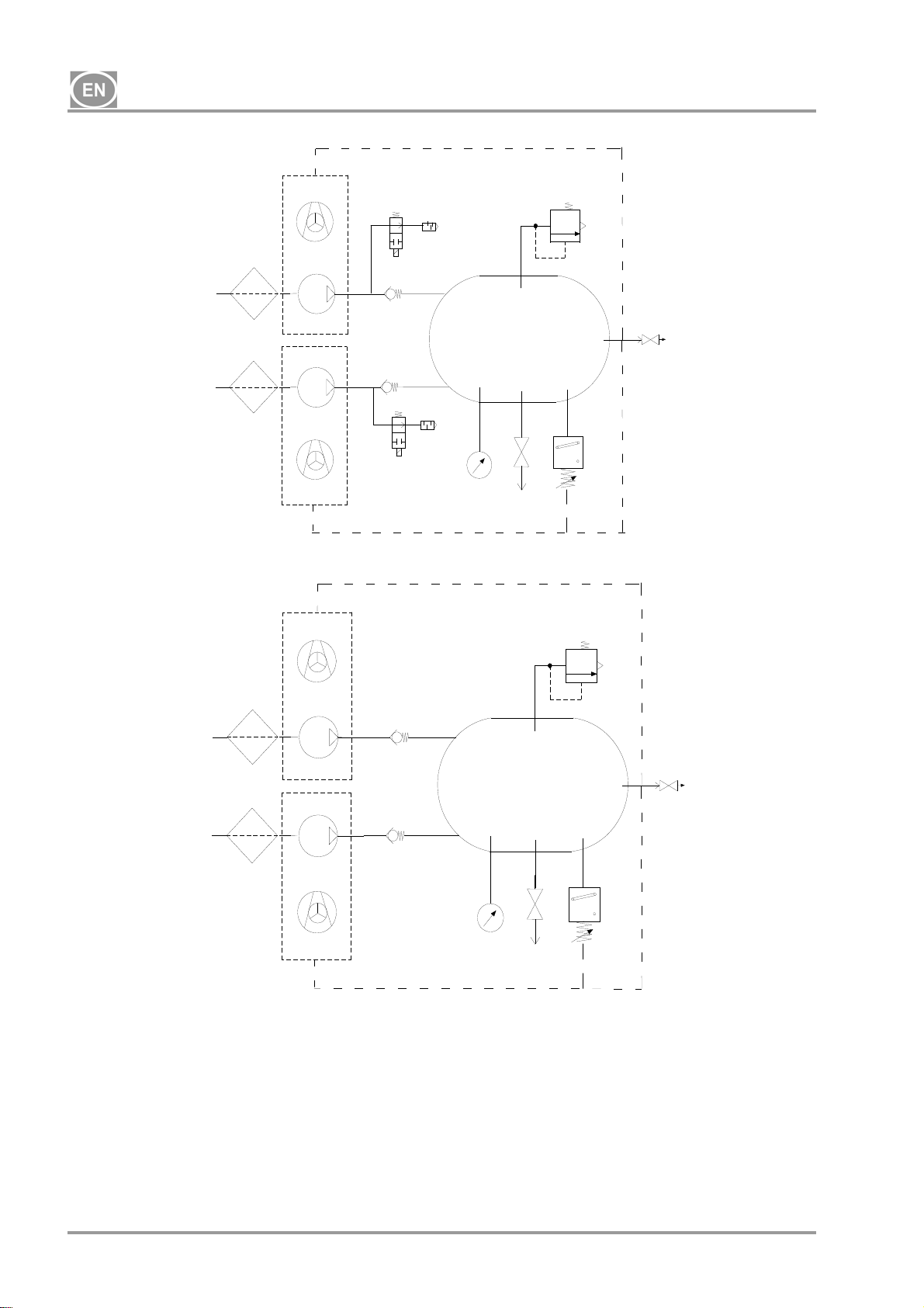
DK50 2x2V/110
DK50 2x2V/110 230V
3
1
2
1
2
DK50 2x2V/110 400V
3
1
2
1
2
Legend for compressed air diagram
1. Inlet filter
2. Motor
3. Fan
4. Relief valve
5. Noise silencer
6. Non-return valve
7. Pressure gauge
8. Pressure switch
4
5
6
10
6
5
4
6
6
7
11
10
11
7
9. Safety valve
10. Air tank
11. Drain valve
12. Cooler
13. Coalescence filter
14. Membrane dryer
15. Condensate drain bottle
16. Condensate drain solenoid valve
17. Outlet valve
9
17
8
9
17
8
NP-DK50 2x2V 110-2_10-2018-MD A - 16 - 10/2018
DK50 2x2V/110
INSTALLATION
11. CONDITIONS FOR USE
Compressors may only be installed and operating in dry, well-ventilated and clean environments
with environmental parameters that meet the requirements specified in Chapter 7, Technical
data. The compressor must be installed so that it is accessible at all times for operating and
maintenance. Please ensure that the label on the device is readily accessible.
The compressor must stand on a flat, sufficiently stable base (be aware of the weight of the
compressor, see Chapter 7, Technical data).
Compressors may not be operated outdoors or in otherwise wet or damp environments. Do not
use the compressor in the presence of explosive gases, dust or flammable liquids.
Before connecting the compressor to medical equipment, the supplier must confirm that it meets
all requirements for its use. Refer to the technical data of the product for this purpose. When a
unit is to be built-in, classification and evaluation of compatibility must be done by the
manufacturer or supplier of the product to be used.
Any other use or use outside this framework is not considered as intended use. The
manufacturer is not responsible for any damages arising from such use. The operator/user
assumes all risks.
Only a qualified professional may install the compressor and place it into operation
for the first time. This professional is obliged to train operating staff as to the use
and maintenance of the device. Installation and training of all operators shall be
confirmed by the installer’s signature on the certificate of installation.
Prior to installation, ensure that the compressor is free of all transport packaging
and stabilizers to avoid any risk of damage to the product.
Parts of the air pump may be hot and reach hazardous temperatures during
compressor operation and may pose a contact risk for operators or materials. Burn
or fire hazard! Caution! Hot surface!
Ambient operating conditions
Temperature: +5°C to +40°C,
Max. relative humidity: 70%,
Max. absolute humidity: 15 g/m
3
.
10/2018 - 17 - NP-DK50 2x2V 110-2_10-2018-MD A
DK50 2x2V/110
12. PLACEMENT OF THE COMPRESSOR
The device shall only be installed by a qualified professional.
Unwrap the compressor from the packaging.
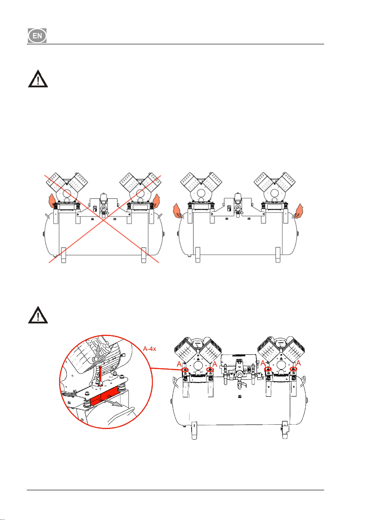
12.1. Handling and releasing the compressor
Position the compressor at the site of future operation (Fig. 5)
Fig. 5
Remove the transport securing elements/bolts from the air pumps. (Fig. 6)
Remove all devices used to secure the air pumps once the compressor set has
been installed and mounted at the site of final installation!
Fig. 6
NP-DK50 2x2V 110-2_10-2018-MD A - 18 - 10/2018
DK50 2x2V/110
12.2. Placement of the compressor in the cabinet
Opening the upper cover (Fig. 4)
Open the lock by turning with a screwdriver as shown in the pictogram and pick up using
the handle.
The gas springs will keep the cover open.
Be careful not to pinch your fingers when closing the cover on the cabinet.
Always lock with the quick releases after closing the cover on the cabinet!
Removal of the front panel on the cabinet (Fig. 4)
Remove the door held on by the 4 (four) M5 screws and disconnect the earthing conductor.
Compressor placement (Fig. 4)
Insert the compressor into the cabinet so the compressed air outlet is pointing towards the
operator.
The dryer fan must be inserted into the ventilation tunnel in the cabinet on compressor
models with a dryer.
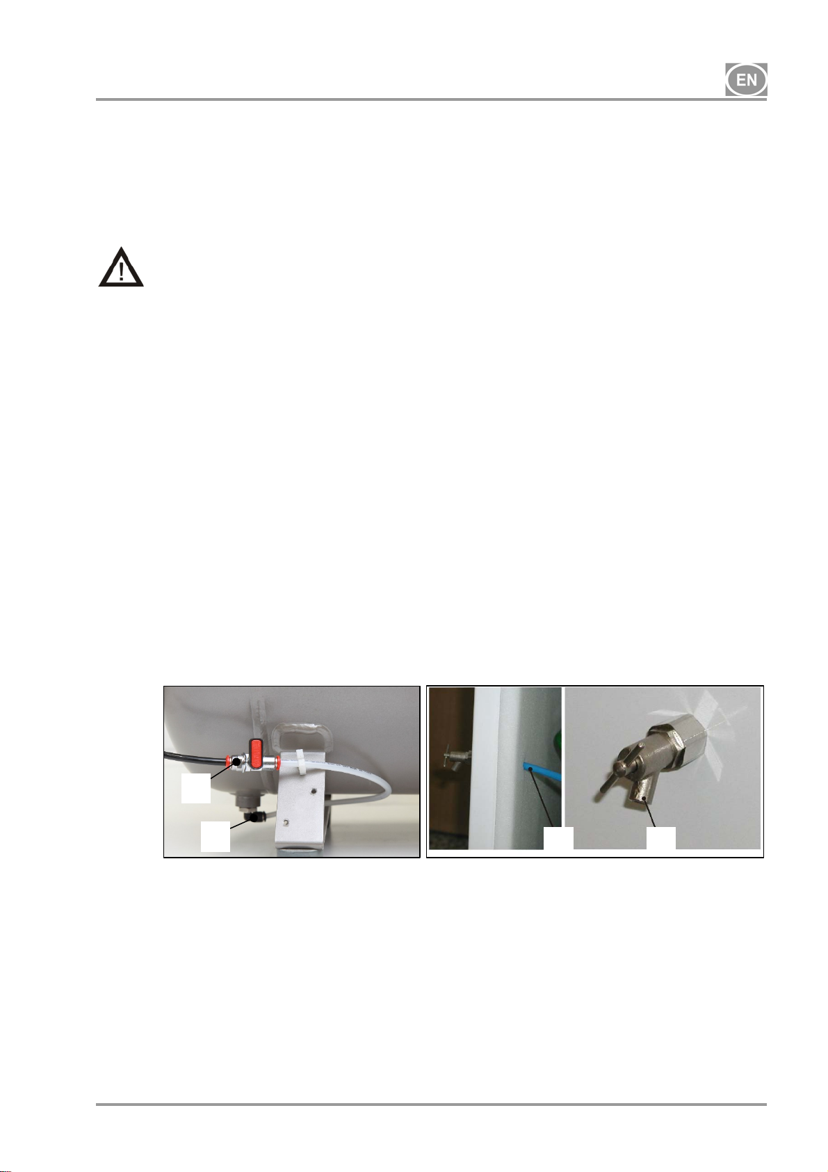
12.3. Valve installation on the condensate drain from the cabinet
(Fig. 7)
For cabinet-mounted compressors, install the threaded fitting with the valve (1) into the hole in the
side of the cabinet and install the PA Ø 8 / Ø 6 hose (2). Insert the other side of the hose into the
fitting (4) beneath the air tank from which the valve (3) and hose are removed.
Use a Ø16.5 plug to close off the hole on the other side of the cabinet.
The fitting with the valve are standard parts delivered with the cabinet. The condensate drain valve
may be installed on either side of the compressor.
3
Fig. 7
4
2 1
10/2018 - 19 - NP-DK50 2x2V 110-2_10-2018-MD A
DK50 2x2V/110
13. PNEUMATIC CONNECTIONS
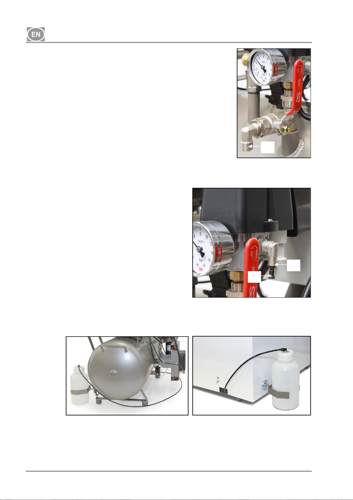
13.1. Compressed air outlet (Fig. 8)
Route the pressure line from the compressed air outlet (1)
on the compressor to the device.
Route the pressure hose through the opening in
the rear wall of the cabinet for cabinet-mounted
compressors.
Fig. 8
13.2. Connecting the cabinet pressure gauge hose to the compressor (Fig.9)
Remove the threaded plug from the pneumatic block
on the compressor. Connect the cabinet pressure
gauge hose to the threaded fitting.
Fig. 9
13.3. Condensate outlet (Fig.10)
1
2
1
Connect the condensate drain hose to the condensate collecting bottle on compressors
with dryers.
Fig. 10
Route the hose through the opening in the rear wall of the cabinet for compressor models
with a dryer.
NP-DK50 2x2V 110-2_10-2018-MD A - 20 - 10/2018
o
p
p
r
n
e
o
e
1
e
e
o
d
A
t
s
L
u
a
t
a
w
n
a
c
o
h
c
n
n
g
V
V
T
a
e
a
n
u
n
m
c
c
t
g
s
g
o
x
z
z
d
e
e
e
d
w
w
c
d
s
d
o
r
e
g
o
e
s
s
m
u
e
s
o
m
w
c
u
c
K
o
a
e
e
DK50
2x2V/11
0
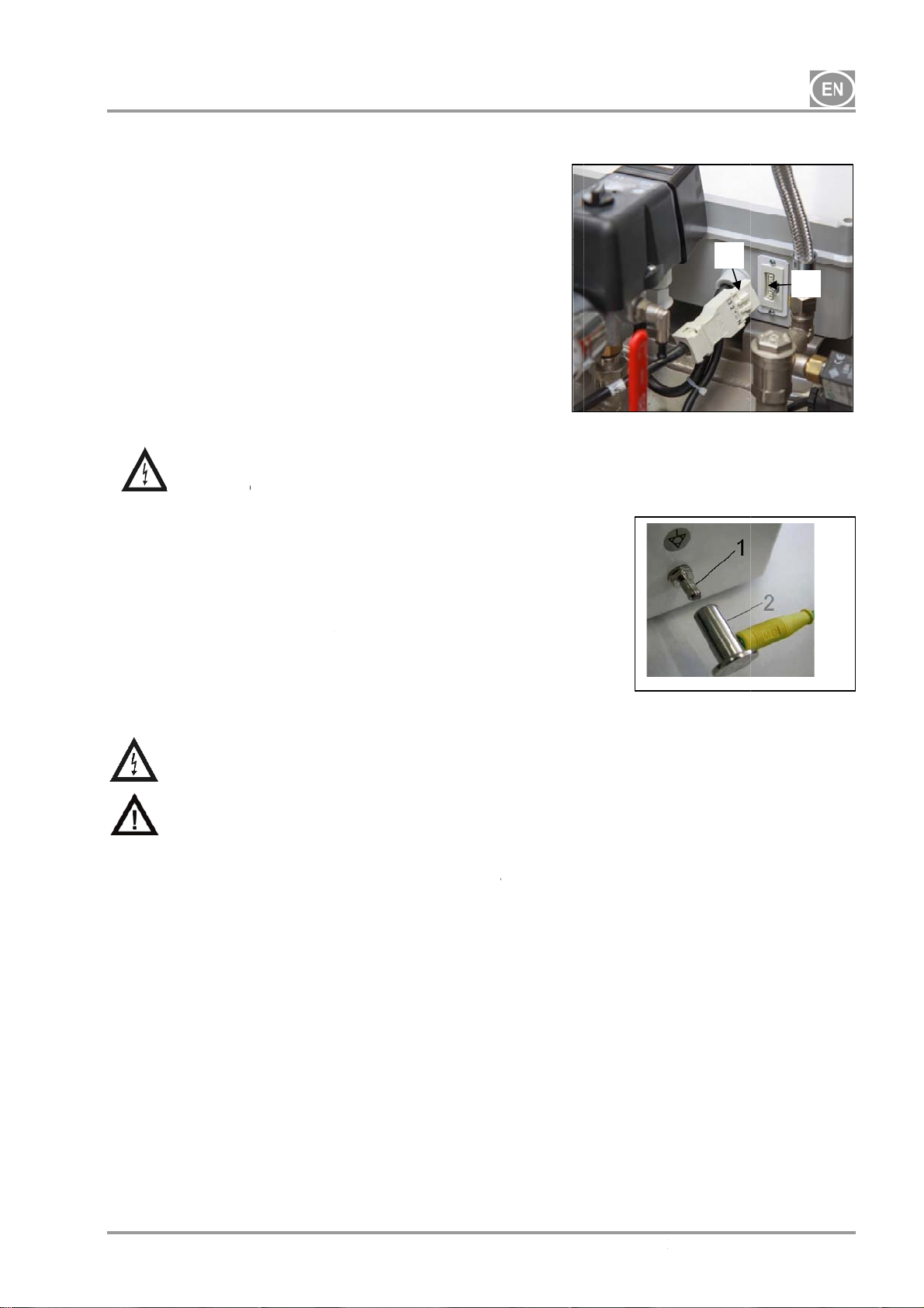
14. EL
The pr
mains
ECTRICA
duct is eq
lug into a r
Kee
eme
from
the socke
gency the
the mains.
Con
elect
(2). (
ect the c
rical cord
Fig. 11)
Rout
wall
the powe
f the cabi
Ensure
electric
frequen
stated
Conn
max.
ction to t
6 A.
Conn
to the
valid
equip
provi
ct the pin
electrical
lectrical e
tential bo
ed in the b
Ensure
electric
If any el
ttach
he earthin
Power
upply feed
CONNEC
ipped with
ted mains
easily acc
device c
binet to t
ith the co
r cord thro
et for cabi
l codes.
n the devi
e power d
for equipo
ircuit usin
gineering
ding (2) i
asic packa
the electri
shock!
ectrical c
conductor
– DK50 2
230
400
full co
y must
/50(60)H
/50(60)H
IONS
a grounde
socket.
ssible to
n be safe
he compr
nector (1)
gh the op
et-mounte
pliance
The main
comply
e's label.
istribution
ential bon
the define
regulations
an acce
e. (Fig. 12
cal cable
rd or air h
to the doo
2V/110
3Gx1.5x
5Gx1.5x
plug. Inse
nsure that
ly disconn
ssor usin
into the s
ning in th
compres
ith all
s voltage
ith the
abinet mu
ing 6 m
d method
. The sock
sory and i
)
oes not t
se is da
and scre
4000
4000
rt the
in an
cted
the
cket
rear
ors.
local
and
data
t be
(1)
nder
t for
not
uch hot
aged it m
it into the
Fig.11
Fig.
ompress
st be repl
abinet.
1
12
r compon
ced imm
2
nts. Risk
diately.
of
10/2018
- 21 -
NP-D
50 2x2V 110-
2_10-2018-M
D A
DK50 2x2V/110
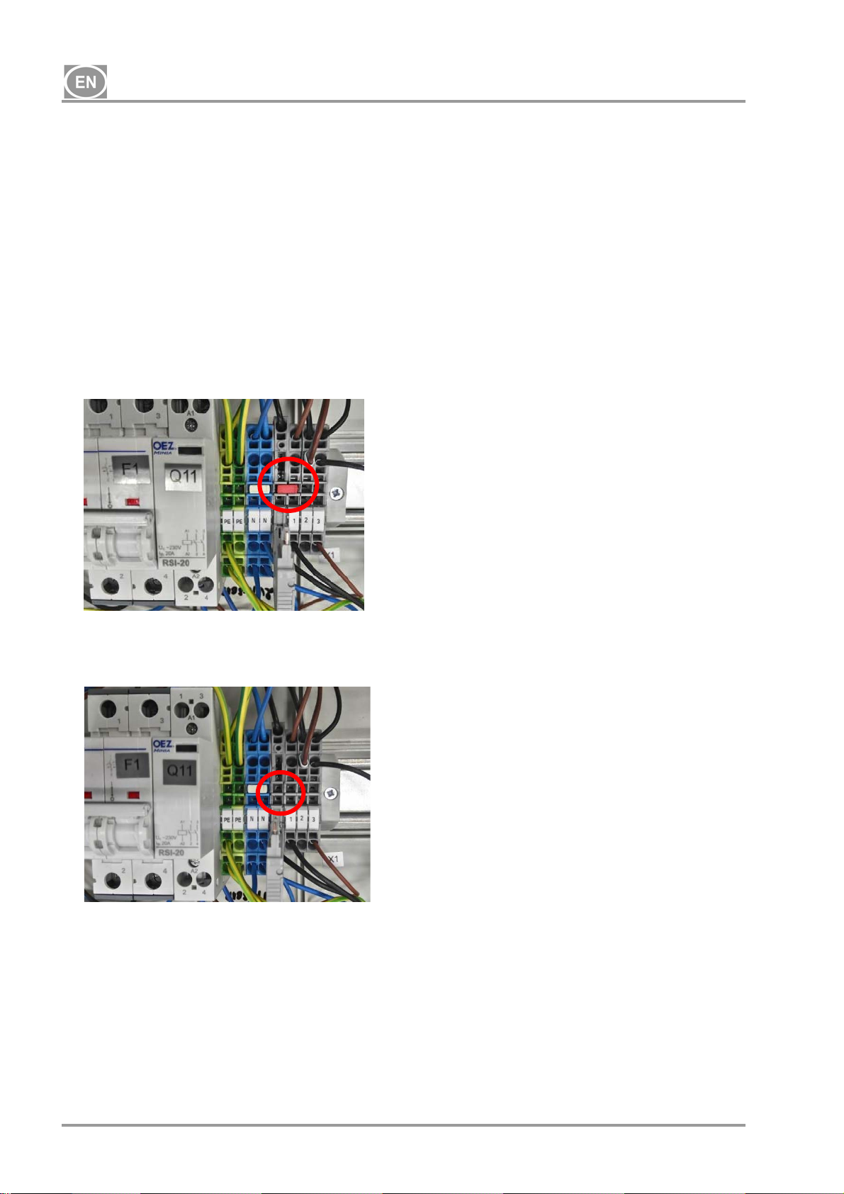
14.1. Jumper removal
Remove the jumper from the terminal strip in the electrical panel for cabinet-mounted
compressors. The switch on the compressor cabinet will not work properly if the jumper is
not removed!
Remove the cover on the electrical panel
Remove the jumper from the terminal strip
Reinstall the cover on the electrical panel
Keep the removed jumper for service purposes (see Chapter 19.11 - Jumper connections).
Compressor with jumper installed
Compressor with jumper removed
NP-DK50 2x2V 110-2_10-2018-MD A - 22 - 10/2018
DK50 2x2V/110
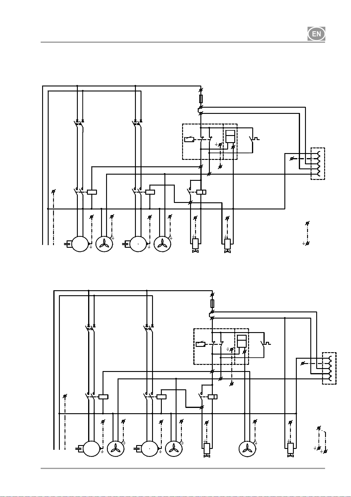
15. CONNECTION DIAGRAM
DK50 2x2V/110 5-7 bar, 6-8 bar, 8-10 bar
1/N/PE ~ 230V/50Hz, 230V/60Hz Hz
ELECTRIC OBJECT OF 1st. CAT.
F1
1
3
2
4
bk1
bu1
PE
bu1
Q11
214
3
A1
A2
UNPE
M
1
~
-M1
DK50 2x2V/110/M 5-7bar, 6-8 bar, 8-10 bar
1/N/PE ~ 230V/50Hz, 230V/60Hz Hz
ELECTRIC OBJECT OF 1st. CAT.
1
F1
2
bk1
PE
Q11
214
bu1
UNPE
-M1
bk1
bu1
1
3
F2
2
4
bk1
bu1
A1
3
Q12
214
A2
-E1
PE
bk1
bu1
M
1
~
-M2
PE
-E2
1
3
PE
3
-B1
p >
15
K1
18
-X1:4
PE
F2
4
bu1
3
A1
2
4
bk1
bu1
3
A1
Q12
A2
PE
M
1
~
PE
-E1
214
M
1
~
-M2
A2
PE
PE
-E2
-F3
T1,6
**
-X1:1
-X1:2
-M10
K1
-X1:4
PE
bk
gy
A1
A2
-B1
15
18
-X1:3
-X1:1
p >
-X1:2
F3:1
F3:2
bn
T
-F3
T1,6
**
bk
gy
A1
A2
PE
-M10
gnye
-X1:3
T
-P1*
h
bu
PE
PE
-M20
F3:1
Mostik zapojit len ak je
kompresor bez skrinky
F3:2
gnye
bn
PE
* - only 8-10 bar
-B2
40°C
Wago222
* - only 8-10 bar
-P1*
h
Wago222
bu
PE
-E3
-B2
40°C
PE
-M4
-X2
N
PE
PE
1
2
3
PE
-X2
N
PE
PE
1
2
3
PE
10/2018 - 23 - NP-DK50 2x2V 110-2_10-2018-MD A
DK50 2x2V/110
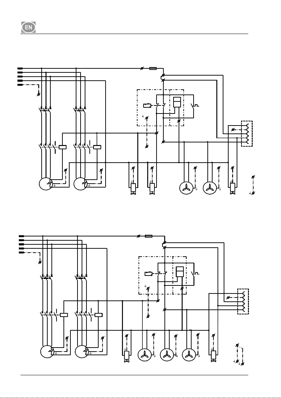
DK50 2x2V/110 5-7 bar, 6-8 bar, 8-10 bar
1/N/PE ~ 400V 50 Hz
MAINS TN-S [TN-C-S]
ELECTRIC OBJECT OF 1st. CAT.
L1
L2
L2
L3
L3
N
N
PE
PE
-F1
1
5
3
1
5
3
-F2
6
2
4
6
2
4
-Q11
13
21436514
-Q12
A1
A2
21436514
A1
13
A2
bk2
bk3
bk1
M
3
~
-M1
PE
bk4
bk5
bk1
bk2
bk3
M
3
~
-M2
PE
bk5
bk4
DK50 2x2V/110/M 5-7bar, 6-8 bar, 8-10 bar
1/N/PE ~ 400V 50 Hz
MAINS TN-S [TN-C-S]
ELECTRIC OBJECT OF 1st. CAT.
L1
L2
L2
L3
L3
N
N
PE
PE
-F1
1
3
5
2
6
4
-F2
1
5
3
2
6
4
-Q11
13
21436514
bk1
bk2
bk3
M
3
~
-M1
-Q12
A1
A2
21436514
PE
bk5
bk4
bk1
3
A1
13
A2
PE
bk2
bk3
M
~
bk5
bk4
PE
-M2
-M10
PE
-M10
F3:1
F3:1
gnye
gnye
-E3
p >
-F3
T1,6
p >
-F3
T1,6
-B1
-X1:2
PE
PE
-M20
-B1
-X1:2
PE
PE
**
bk
gy
bn
**
bk
gy
bn bu
* - only 8-10 bar
Mostik zapojit len ak je
kompresor bez skrinky
F3:2
-X1:1
-P1*
h
bu
-X1:3
F3:2
-X1:1
-P1*
h
-X1:3
PE
-E1
-B2
40°C
Wago222
PE PE
-E1
* - only 8-10 bar
-B2
40°C
Wago222
PE
-E2
-E2
PE
-M4
PE
PE
PE
-M4
-X2
PE
1
-X2
N
PE
1
2
3
PE
N
2
3
PE
NP-DK50 2x2V 110-2_10-2018-MD A - 24 - 10/2018
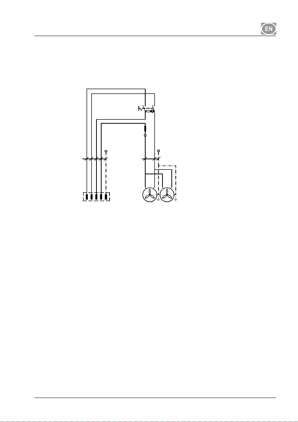
DK50 2x2V/110
Compressor cabinet
S110
1/N/PE ~ 230V/50Hz
ELECTRIC OBJECT OF 1st. CAT.
bn bu bk gy
5G0.75
PE
-X10
1
N23PE
Legend for electrical diagram
M1,M2 Compressor motor
E1,E2 Compressor fan
E3 Dryer fan
M10,M20 Relief valve
B2 Temperature switch
E10,E11 Cabinet fan
X10 Connector
X2 Socket
Note:
* - For 8-10 bar compressor models, an hourly meter is installed on the pressure switch.
** - Only connect the jumper for compressorswithout cabinet (Chapter.19.11)
-S10
gn
1
bn
bu
PE
3G0.5
-E11-E10
B1 Pressure switch
X1 Terminal strip
M4 Condensate drain valve
P1* Hour meter
S10 Switch
K1 Timer relay
F1,2 Breaker
Q11,12 Contactor
10/2018 - 25 - NP-DK50 2x2V 110-2_10-2018-MD A
DK50 2x2V/110
OPERATION
IN CASE OF EMERGENCY, DISCONNECT THE COMPRESSOR FROM THE MAINS
(PULL OUT THE MAINS PLUG).
THE AIR PUMP HAS HOT SURFACES.
BURNS OR FIRE MAY RESULT IF CONTACT IS MADE.
During prolonged operation of the compressor, the temperature in the cabinet
may increase to over 40°C. At this point the cooling fan automatically switches
on. After cooling the space to under 32°C, the ventilator switches off.
Automatic start: when pressure in the pressure tank decreases below the switchon pressure, the compressor automatically switches on. The compressor
automatically switches off when pressure in the air tank reaches the switch-off
pressure.
The working pressure settings for the pressure switch set by the manufacturer
cannot be changed. Compressor operation at a working pressure below the
switch-on pressure indicates high air consumption (see the chapter Malfunctions)
Required drying performance can only be achieved when following the defined
operating conditions!
Drying performance will decline and the achieved dew point will drop if the dryer
is operated at any pressure below the minimum working pressure!
WHEN THE DRYER IS OPERATED AT AMBIENT TEMPERATURE THAT IS HIGHER
THAN MAXIMUM OPERATING TEMPERATURE, THE DRYER MAY BE DAMAGED!
16. COMMISSIONING
Make sure all transport stabilizers were removed.
Check that all pressurized air line connections are secure.
Check to ensure power is connected correctly to the compressor.
Check to ensure the switch is in the “I” position. Turn the switch (2) to the “I” position if found in
the “0” position. (Fig. 13)
For cabinet-mounted compressors, turn the switch (4) on the front side of the cabinet to the "I"
position; a green indicator indicates the device is in operation. (Fig. 13)
Check the connection of the cabinet connector to the compressor. (Fig. 11)
Check to ensure the jumper has been removed from the terminal strip in the electrical panel for
cabinet-mounted compressors. (chap.14.1.)
Check the connection of the the cabinet pressure gauge hose to the compressor pneumatic
block. (Fig.4 and9)
The compressor is not equipped with a backup power supply.
NP-DK50 2x2V 110-2_10-2018-MD A - 26 - 10/2018
DK50 2x2V/110
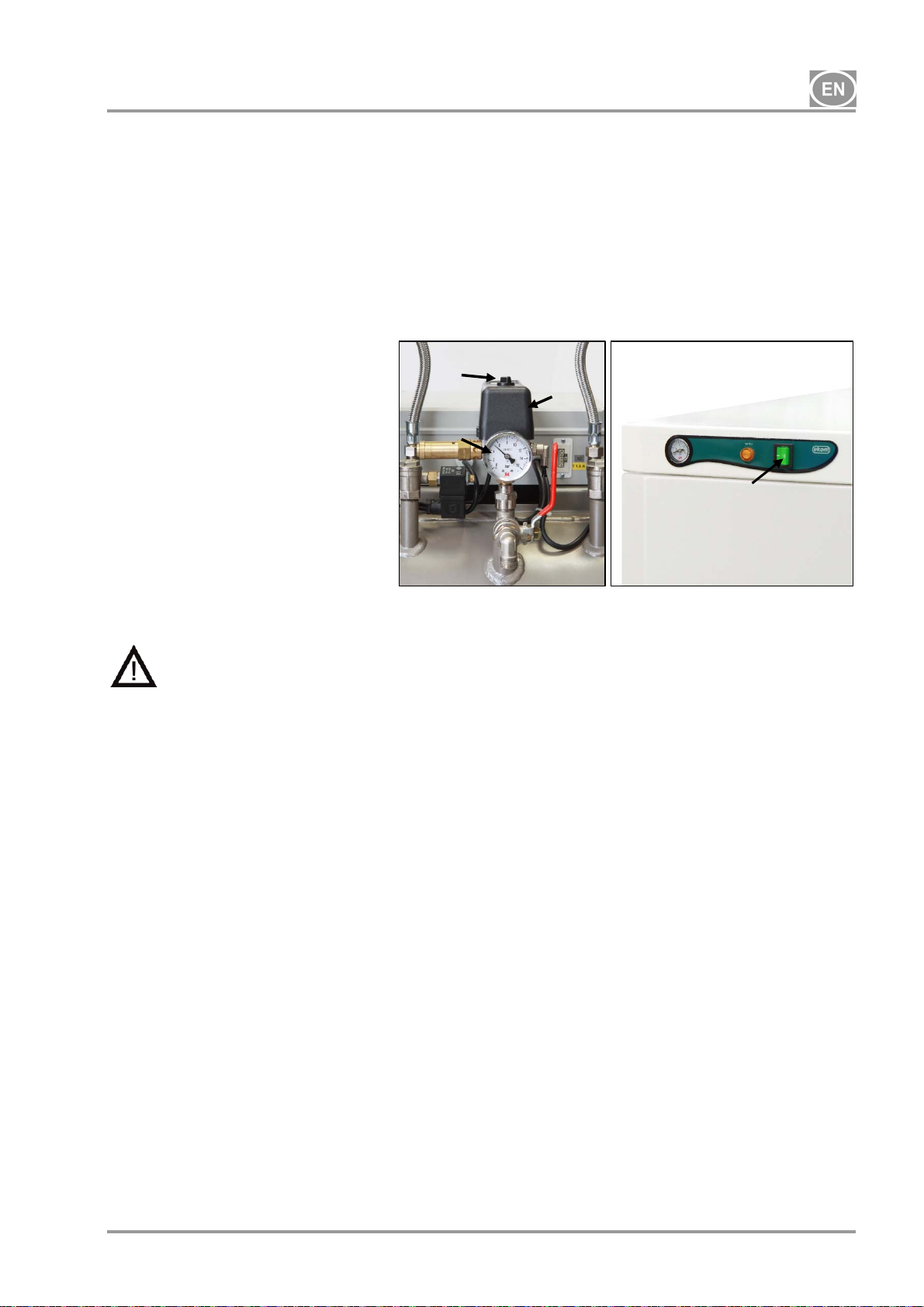
17. SWITCHING THE COMPRESSOR ON
(Fig. 13)
Start the compressor at the pressure switch (1) by turning the switch (2) to the “I” position. Turn on
the switch (4) on the front of the cabinet for compressors in the cabinet, the indicator will turn
green.The compressor begins running, the air tank is filled, and the switching pressure and
pressure switch turn the compressor off. The compressor operates in automatic mode, switched
on and off by the pressure switch, depending on compressed air consumption.
Check the values of the switch-on and switch-off pressure using the pressure gauge (3). A
tolerance of 10% is acceptable. The pressure in the air tank must not exceed the permitted
operating pressure.
Fig.13
Adjustments to the pressure range on the compressor’s pressure switch are
prohibited. The pressure switch (1) was set up by the manufacturer and only a
qualified technician trained by the manufacturer may make any changes to its
settings.
Compressor – when first started and placed into service, the compressor fills the air tank until the
switching pressure and the pressure switch turn off the compressor. The compressor operates in
automatic mode, switched on and off by the pressure switch, depending on compressed air usage.
2
1
3
4
Compressor with dryer – the compressor operates in the same manner as above, only the
compressed air passes through a cooler and a dryer that removes moisture from the compressed
air.
Compressor with a condensation and filtration unit (KJF-2) - during usage by the device, the
compressed air passes through the KJF-2 unit, where the air is cooled, filtered and condensed
liquid is captured and automatically drained into a collecting bottle.
18. COMPRESSOR SHUT-DOWN
(Fig.13)
Compressor shut-down for either service or any other reason is performed at the pressure switch
(1) by turning the alternation switch (2) to the “0” position and pulling the mains plug from the
socket. This disconnects the compressor from power supply. Then open the drain valve (Fig. 14)
to decrease the pressure in the air tank to zero.
10/2018 - 27 - NP-DK50 2x2V 110-2_10-2018-MD A
DK50 2x2V/110
MAINTENANCE
19. DEVICE MAINTENANCE
Warning!
The operator shall ensure completion of repeated testing of the device at least once every
24 months (EN 62353) or at intervals defined by applicable national legal regulations. A
record of these test results shall be completed (e.g. per EN 62353, Annex G) together with
the measurement methods.
The device has been designed and manufactured to keep maintenance to a minimum. The
following work must be performed to retain the proper and reliable operation of the compressor.
For 8-10 bar compressor models, an hourly meter is installed on the pressure switch.
The work below may only be performed by trained personnel as follows:
Before starting compressor maintenance work, it is necessary to check it the
compressor can be disconnected from the device to ensure that the person using
the device is not at risk of health damage and there is no risk of any other
material damages!
Air pump components (head, cylinder, pressure hose, etc.) are very hot during
and shortly after compressor operation – do not touch these components!
Repair works beyond normal maintenance can be performed only by qualified
personnel or he manufacturer’s customer service.
Use only spareparts and accessories approved by the manufacturer.
PROTECT EYESIGHT, WEAR GOGGLES, WHEN VENTING COMPRESSED AIR
FROM THE COMPRESSED AIR CIRCUIT (AIR TANK).
BEFORE STARTING ANY MAINTENANCE WORK, FIRST DISCONNECT THE
COMPRESSOR FROM THE MAINS (PULL OUT THE MAINS PLUG) AND VENT THE
COMPRESSED AIR FROM THE AIR TANK.
NP-DK50 2x2V 110-2_10-2018-MD A - 28 - 10/2018

DK50 2x2V/110
19.1. Maintenance intervals
Time interval *** once
a day
Product operational checks
Drain condensate from the
air tank )**
- At high humidity
Drain condensate from the
air tank )**
- At normal humidity
Product function check x
Leak check connections and
inspect device
Inspection of electrical
connections
Cooler and fan check
Filter element replacement
in the dryer filter
Filter element replacement
in theKJF-2
Safety valve check x
Conduct a “repeated test”
per EN 62353
Replacing the inlet filter and
pre-filter on the DK50 2V air
pump )*
)* data is presented in hours; if not possible, then the data is considered in years
)** only for compressors without dryers
)*** For 60 Hz compressor models, reduce the time interval in hours by 20%
(2000 h/1600 h, 4000 h/3200 h, 6000 h/4800 h, 8000 h/6400 h, 10000 h/8000 h, 12000 h/9600 h)
once
a week
x
x
x
x
x
x
x
x
once
a year
once
every 2
years
x 19 -
2000
hours
x x
4000
hours
6000
hours
19.2 - user
8000
hours
19.6 -
10000
hours
x x 19.7
12000
hours Chapter
Set of spare
parts
19.5 - user
19.5 - user
9 - user
19.3 -
19.4 -
19.10 -
19.8 025200305-000
19.9 025200061-000
025200139-000
025200150-000
Performed by
qualified
professional
qualified
professional
qualified
professional
qualified
professional
qualified
professional
qualified
professional
qualified
professional
qualified
professional
10/2018 - 29 - NP-DK50 2x2V 110-2_10-2018-MD A
 Loading...