

EKOM DK50 2V Mobile, DK50 Plus Mobile Instructions For Use And Service Manual

COMPRESSOR
KOMPRESSOR
COMPRESSORE
DK50 2V/M MOBILE
MANUFACTURER
HERSTELLER
PRODUTTORE
EKOM spol. s r. o.
Priemyselná 5031/18
SK-921 01 Piešťany
Slovak Republic
tel.: +421 33 7967255
fax: +421 33 7967223
www.ekom.sk
email: ekom@ekom.sk
DATE OF LAST REVISION
DATUM DER LETZTEN ÜBERARBEITUNG
DATA DELL'ULTIMA REVISIONE
07/2015

07/2015 - 3 - NP-DK50 Plus, DK50 2V -MOBILE-MD-16_07-2015
CONTENTS................................. 2
INHALT....................................... 16
CONTENUTO.............................. 28
JULY 2015
Z-1238/2015
Pgs. 31 - pos.3,31

INSTRUCTIONS FOR USE
NP-DK50 Plus, DK50 2V -MOBILE-MD-16_07-2015 - 2 - 07/2015
CONTENTS
INSTRUCTIONS FOR USE ..................................................................................................................... 3
IMPORTANT INFORMATION ............................................................................................................. 3
1. CE MARKING ............................................................................................................................ 3
2. WARNINGS ................................................................................................................................ 3
3. ALERT NOTICES AND SYMBOLS ............................................................................................ 4
4. STORAGE AND TRANSPORT .................................................................................................. 4
5. TECHNICAL DATA ..................................................................................................................... 5
6. PRODUCT DESCRIPTION ........................................................................................................ 6
7. FUNCTION ................................................................................................................................. 6
INSTALLATION ................................................................................................................................... 9
8. USE ............................................................................................................................................. 9
9. INSTALLATION .......................................................................................................................... 9
10. FIRST OPERATION ................................................................................................................. 11
OPERATION ..................................................................................................................................... 11
11. SWITCHING THE COMPRESSOR ON ................................................................................... 11
MAINTENANCE ................................................................................................................................ 12
12. MAINTENANCE SCHEDULE ................................................................................................. 12
13. MAINTENANCE ........................................................................................................................ 12
14. STORAGE ................................................................................................................................ 14
15. DISPOSING OF THE APPLIANCE .......................................................................................... 14
16. REPAIR SERVICE .................................................................................................................... 14
17. SOLVING PROBLEMS ............................................................................................................. 14
SERVICE MANUAL ............................................................................................................................ 41
18. WIRING DIAGRAMS ............................................................................................................. 41
19. SPARE PARTS ....................................................................................................................... 44
PARTS LIST ........................................................................................................................................ 60

INSTRUCTIONS FOR USE
07/2015 - 3 - NP-DK50 Plus, DK50 2V -MOBILE-MD-16_07-2015
INSTRUCTIONS FOR USE
IMPORTANT INFORMATION
1. CE MARKING
Products labeled with compliance mark CE meet safety Guidelines of the European Union. (98/37/EEC Council Directive of Safety of Machinery, 73/23/EEC – Low-voltage directive), EMC.
2. WARNINGS
2.1. General warnings
This Installation, Operation and Maintenance Manual is a part of the appliance and must be kept with the
compressor. Careful review of this manual will provide the information necessary for correct operation of
the appliance.
The safety of operating personnel and trouble-free operation of the appliance are guaranteed only if
original parts are used. Only accessories and parts mentioned in the technical documentation or expressly
approved by the manufacturer can be used.
If any other accessories or consumable materials are used, the manufacturer cannot be held responsible
for the safe operation of the appliance. This guarantee does not cover damages originating from the use
of accessories or consumable material other than those specified or suggested by the manufacturer.
The manufacturer guarantees the safety, reliability and function of the appliance only if:
- Installation, new settings, amendments, extensions and repairs are performed by the manufacturer or
its representative, or a service provider authorized by the manufacturer
- The appliance is used in accordance with this Installation, Operation and Maintenance Manual
The manufacturer reserves all rights for the protection of its wiring diagrams, methods and names.
Translation of Manual for Installation, Operation and Maintenance is carried out in accordance with the
best knowledge. In the case of ambiguities, the Slovak version of the text prevails.
2.2. General safety warnings
The manufacturer developed and designed the equipment in such a way so that any risks were excluded if it
is used according to intention. The manufacturer considers it to be its obligation to describe the following
safety measures in order to exclude residual damages.
Operation of the appliance must be in compliance with all local codes and regulations.
Original packaging should be kept for the return of the appliance. Only the original packaging ensures
protection of the appliance during transport. If it is necessary to return the appliance during the guarantee
period, the manufacturer is not liable for damages caused by improper packaging.
Each time the appliance is used, the operator must make sure that it is functioning correctly and safely.
The user must fully understand the operation of the appliance.
The product is not intended for operation in areas with a risk of explosion.
2.3. Electrical system safety warnings
The appliance must be connected to earth (grounded).
Before the appliance is plugged in, make sure that the mains voltage and mains frequency stated on the
appliance are the same as the power mains.
Prior to putting into operation it is necessary to check for possible damage of the equipment and
connected air and electric distributions. Damaged pneumatic and electric lines must be immediately
replaced.
Immediately disconnect the appliance from the elektric mains if a technical failure occurs.
During repairs and maintenance, ensure that:
- The appliance is disconnected from the mains
- Pressure pipes are vented and pressure is released from the air tank.
The appliance must be installed by an approved, qualified technician.
INSTRUCTIONS FOR USE
NP-DK50 Plus, DK50 2V -MOBILE-MD-16_07-2015 - 4 - 07/2015
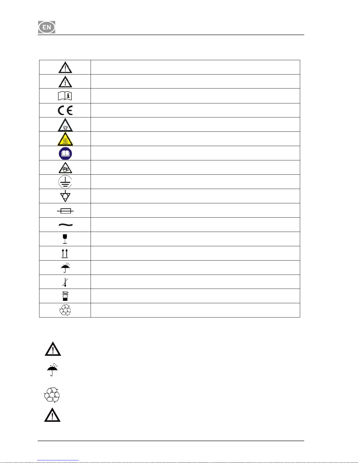
3. ALERT NOTICES AND SYMBOLS
In the Installation, Operation and Maintenance Manual and on packaging and product, the following labels or
symbols are used for important information:
Information, instructions and cautions for the prevention of damage to health or
materials
Caution, risk of electric shock
Consult instructions for use
CE mark of compliance
Compressor is remote-controlled and may start without warning
Caution! Hot surface
Instruction : read the user manual.
Caution : Performed maintenance works
Earth (ground) connection
Terminal for ground connection
Fuse
Alternating current
Handling mark on package – FRAGILE
Handling mark on package – THIS SIDE UP
Handling mark on package – KEEP DRY
Handling mark on package – TEMPERATURE LIMITATIONS
Handling mark on package – LIMITED STACKING
Mark on package – RECYCLABLE MATERIAL
4. STORAGE AND TRANSPORT
The compressor is shipped in cardboard that protects the appliance from damage during transport.
Caution! For transport, always use the original packaging and secure the compressor in
the upright position.
Protect the compressor from humidity and extreme temperatures during transport and storage. A
compressor in its original packaging can be stored in a warm, dry and dust-free area. Do not
store near any chemical substances.
Keep packaging material if possible. If not, please dispose of the packaging material in an
environmentally friendly way and recycle if possible.
Caution! Before moving or transporting the compressor, release all the air pressure from
the tank and hoses and drain the condensed water.
INSTRUCTIONS FOR USE
07/2015 - 5 - NP-DK50 Plus, DK50 2V -MOBILE-MD-16_07-2015
Climatic conditions during storage and transport
Temperature : –25°C to +55°C, 24 h to +70°C
Relative air humidity : 10% to 90 % (no condensation)
Climatic operation conditions
Temperature : +5°C to +40°C
Relative air humidity : 70%
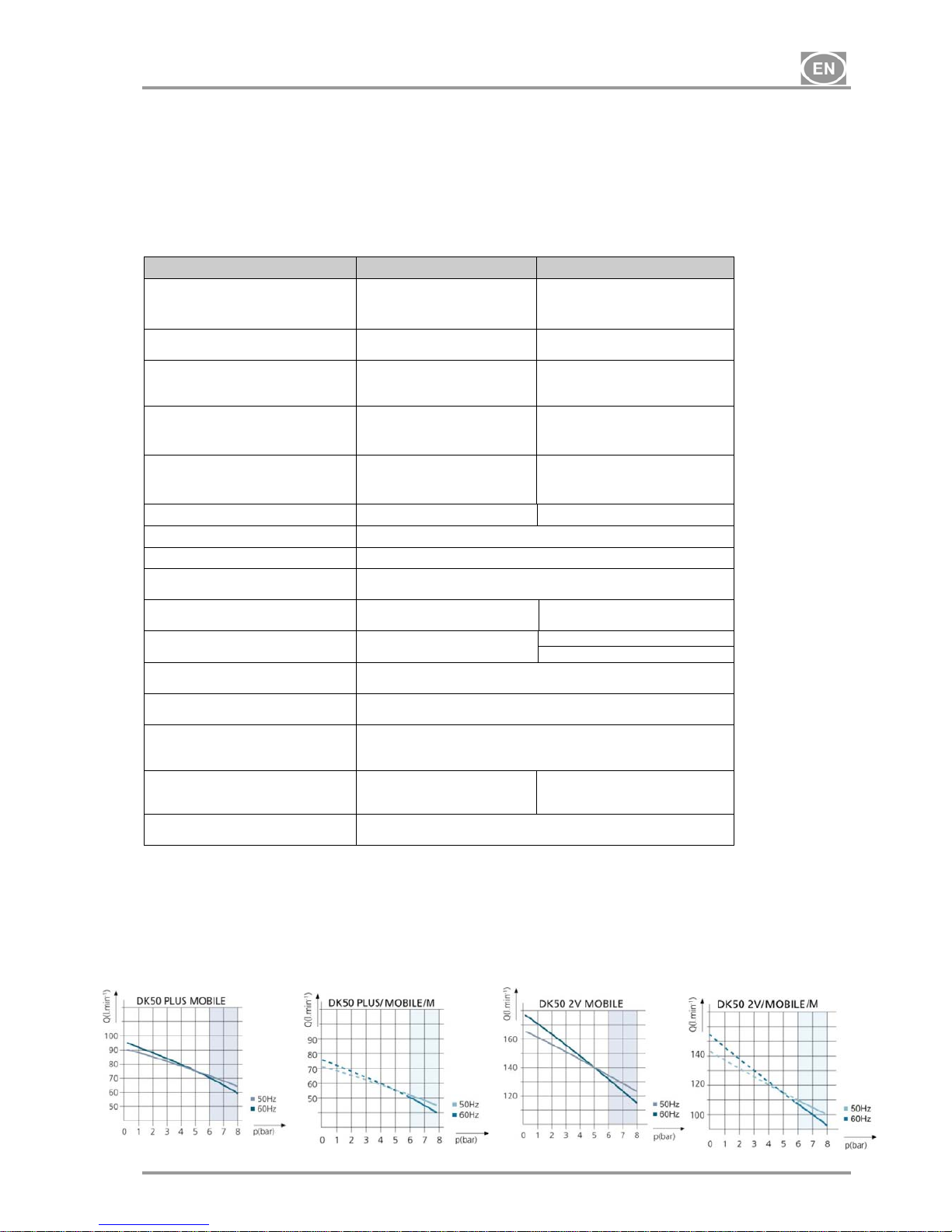
5. TECHNICAL DATA
DK50 PLUS MOBILE DK50 2V MOBILE
Nominal voltage / (*)
frequency
V / Hz
230 / 50
230 / 60
115 / 60
230 / 50
230 / 60
115 / 60
Efficiency of compressor at overpressure 6 bar Lit.min
-1
72 (50Hz)
70 (60Hz)
134 (50Hz)
132 (60Hz)
Efficiency of compressor with
dryer at over-pressure 6 bar
Lit.min
-1
60 (50Hz)
55 (60Hz)
105 (50Hz)
100 (60Hz)
Maximal current
A
3,5
4,4
8,8
7,8
8,8
16,4
Maximal current of compressor
with dryer
A
3,7
4,6
9
8,1
9,1
16,6
Motor performance kW
0,55 1,1
Air tank capacity Lit.
25
Pressure range bar
6,0 – 8,0
Maximum operating pressure of
safety valve bar
12,0
Sound level L
pfA
[dB] 57 (50Hz)
59 (60Hz)
62 (50Hz)
64 (60Hz)
Mode of operation of compressor
Continual S 1
Continual S 1
Intermittent S 3-60% (**)
Mode of operation of compressor
with dryer
Continual S 1
Dimensions of compressor
w x l x h mm
580x700x1010
Dimensions of compressor
packaged in cardboard
w x l x h mm
740x860x1200
Weight of compressor /
of compressor with dryer kg
100 / 105 104 / 110
Drying point of compressor
Atmospheric condensation point
-20°C
(*) When ordering, please specify the version of the compressor
(**) Applicable for voltage version of
115/60
- Air outgoing from membrane dryer M is filtered using 0,3µm filter
INSTRUCTIONS FOR USE
NP-DK50 Plus, DK50 2V -MOBILE-MD-16_07-2015 - 6 - 07/2015
5.1. FAD efficiency correction for differences in elevation
FADcorrectiontable
FAD efficiency refers to conditions at an elevation of 0 mamsl: Temperature: 20°C
Atmospheric pressure: 101325 Pa
Relative humidity: 0%
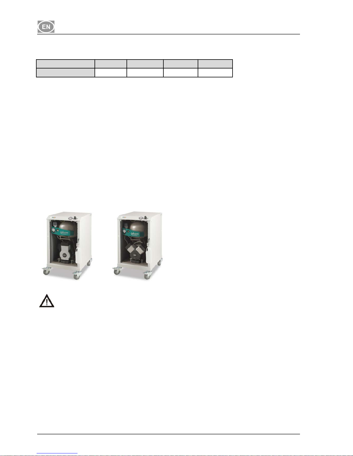
6. PRODUCT DESCRIPTION
6.1. Model variations and their uses
Compressors are the source of clean, oil-free compressed air used to drive appliances and pneumatic
equipment.
Compressors models are designed for the following uses:
Compressors DK50 PLUS MOBILE
DK50 2V MOBILE
- are placed in soundproof boxes.
Compressors DK50 PLUS/M MOBILE
DK50 2V/M MOBILE
- are placed in soundproof boxes and feature an membrane air dryer.
DK50 PLUS MOBILE DK50 2V MOBILE
The compressed air from a compressor is not suitable for the operation of breathing
appliances or similar equipment.
7. FUNCTION
Compressor (Fig.1 )
The compressor (1) draws in air through a filter (8) and compresses it through a check valve (3) into an air
tank (2). The connected apparatus draws the compressed air from the air tank until the pressure drops to a
default preset level on the air-pressure switch (4) switching the compressor on. The compressor again
compresses air into the nozzle until the maximum pressure is reached and the compressor switches off.
After compressor aggregate is switched off, pressure hose shall be pressure-release solenoid valve (6).
Safety valve (5) prevents the pressure in air chamber from rising above the maximal allowed value. The
automatic drain of the condensate (Autodrain) (15) releases the condensate from the air nozzle.
Compressed, clean air free from oil traces is stored in the air tank ready for use.
Compressor with dryer (Fig.2)
The compressor unit (1) pulls in outside air through the inlet filter (8) and compresses it through the cooler
(14), filter (13) and micro-filter (12) to the dryer (9) and on through the check valve (3) as dry clean air in the
air tank (2). Condensate from the filter and micro-filter is automatically drained into the collection vessel. The
dryer provides continuous drying of the compressed air.
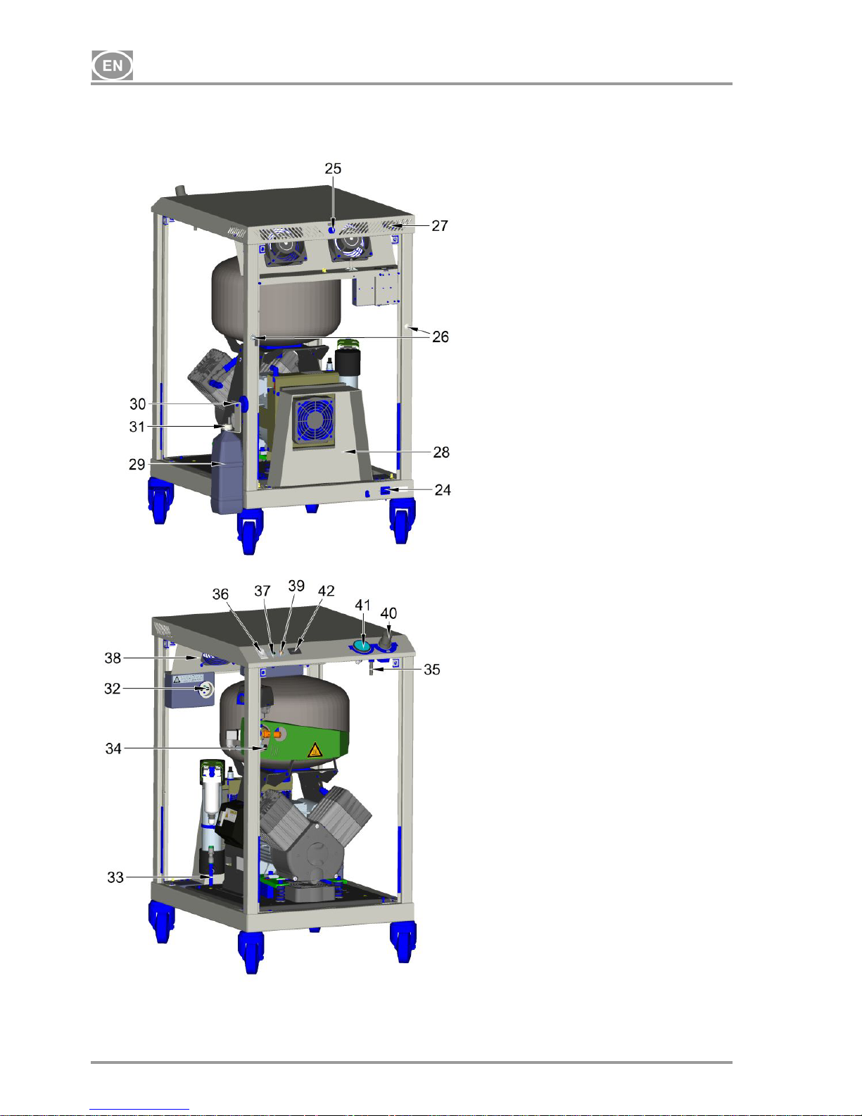
Box of the compressor (Pic. No. 3)
Box is designed with casters (2 – braked and 2- without brake) in a way that internal shape of the box
ensures proper position of the compressor. Increased stiffness of the box constructions and used durable
Elevation[mamsl] 0‐1500 1501‐2500 2501‐3500 3501‐4500
FAD[l/min] FADx1 FADx0.8 FADx0.71 FADx0.60

INSTRUCTIONS FOR USE
07/2015 - 7 - NP-DK50 Plus, DK50 2V -MOBILE-MD-16_07-2015
17
casters ensure easy and simple handling. Box consists of base construction (with casters) and lid joint with
4 posts. There is also cover consisting of 4 boards (doors). Each board (doors) can be removed after are 2
no delay screws unscrewed.
There are manometer of output pressure, pressure control, power switch, visual signaling ON/OFF (green
light), signaling of decreased temperature of the box (orange light), hour meter in the front part of the upper
lid of the box. Box is electrically connected with compressor trough the electric cord in the socket (32).
Electric socket is in the down back part of the box (24). Pneumatic connection is made by hose Ø 6/4 for
draining of the condensate from drier with bush of the condensate output from the box (25) and output of the
pressurized air from the compressor (34) is made by hose Ø 10/8 (35) into press control (40) of the box.
Output of the pressurized air with internal thread G1/4 is placed on the top of the box (26). For draining the
condensate is on the whichever side of the chosen post made hose bush. Draining of the condensate from
the box is possible to do through these bushes in the posts of the box. (26). After switching on the power
switch (36) of the box, equipment works in automatic mode.
In the back part of the box are cooling fans (38), blowing the hot air out of the box through vents for hot air
output (27). Cooling fans are activated by thermal switch when is reached temperature 40 °C. Fans works
until the temperature of the box decreases on the value 32 °C. Mode of increased temperature (above 80 °C)
in the box – COOLING ERROR – is signalized by orange light in the board (39). It is activated by thermal
switch.
Make sure that nothing impedes the free flow of air under and around the compressor.
Never cover the hot air outlet on the top back side of the case.
Fig.1 – Compressor
Fig. 2 - Compressor with membrane air dryer
1. Compressor motor
2. Air tank
3. Check valve
4. Pressure switch
5. Safety valve
6. Solenoid valve
7. Fan of compressor
8. Input filter
9. Dryer chamber
10. Silencer
11. Bottle
12. Mikrofilter
13. Filter
14. Cooler
15. Autodrain
16.
Vessel cap
17.
Check valve
17
INSTRUCTIONS FOR USE
NP-DK50 Plus, DK50 2V -MOBILE-MD-16_07-2015 - 8 - 07/2015
Fig.3 - Box
A- Cabinet (without panels) – rear
view
24. Socket
25. Air pressure output (internal thread
G 1/4“)
26. Variant holes for condensate outlet
from housing for hose with Ø 6/4
27. Heated air output holes
28. Tunnel of ventilator for dryer
29. Bottle for condensate collection
30. Magnetic vessel holder
31. Vessel cap
B- Housing (without panels) with
compressor DK50 2V/M
32. El. socket for compressor
33. Output from a filters for condensate
outlet via hose with Ø 6/4
34. Output of compressed air from
compressor via hose with Ø 10/8
35. Place for input of hose with Ø 10/8
into pressure regulator from output of
compressed air from compressor
36. Mains switch
37. Green indicator of mains switch
turning on
38. Ventilators
39. Orange indicator of operation mode
at raised temperature
40. Pressure regulator
41. Manometer
42. Hour meter
INSTRUCTIONS FOR USE
07/2015 - 9 - NP-DK50 Plus, DK50 2V -MOBILE-MD-16_07-2015
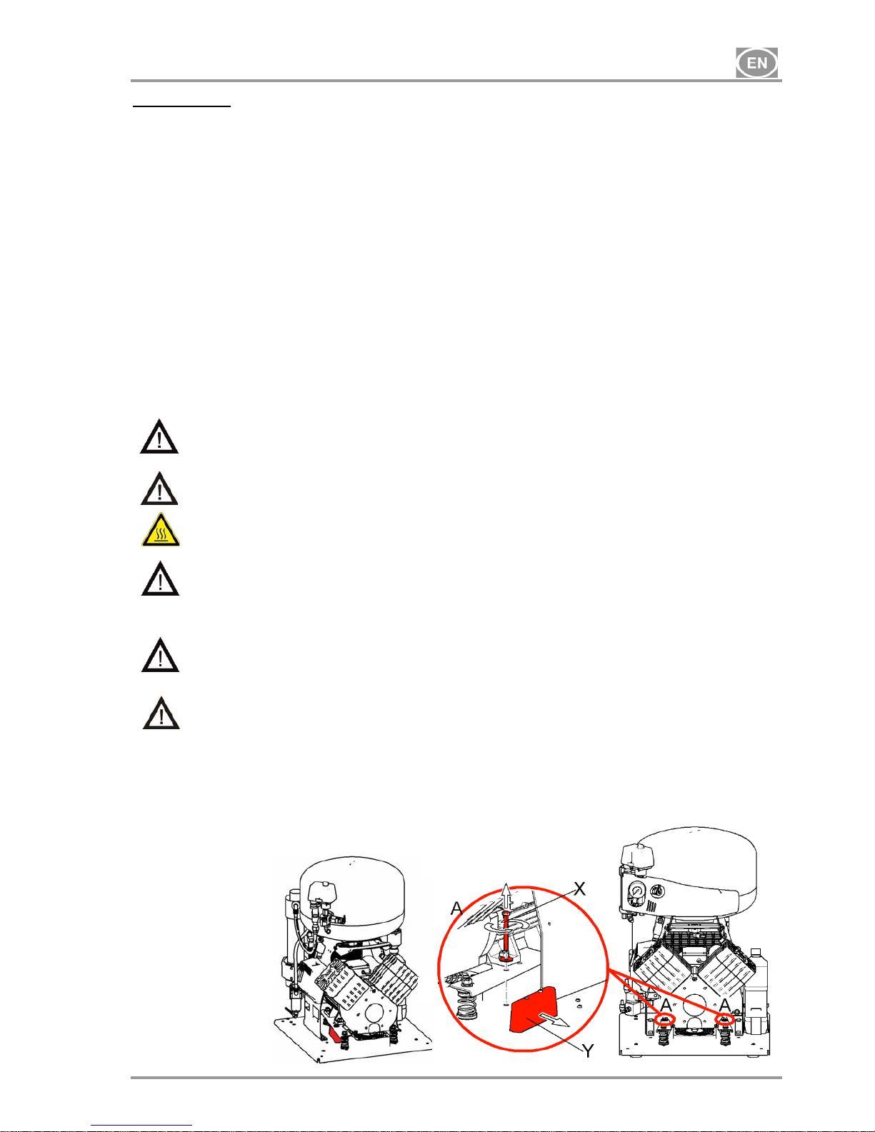
Unpacking Fig.4
INSTALLATION
8. USE
The appliance must be installed and operated in a dry, well ventilated and dust-free area where ambient
temperature is within the range of +5°C to +40°C and relative air humidity does not exceed 70%.
Otherwise, failure-free operation of the compressor cannot be guaranteed. The compressor must be
installed so that it is accessible at all times for operation and maintenance. Please ensure that the
appliance label is accessible.
The appliance must stand on a flat, sufficiently stable base. See paragraph 5 (Technical data) when
positioning or lifting the compressor.
Compressors cannot be exposed to outdoor environments. The appliance cannot be used in moist or wet
environments. Do not use the compressor in the presence of explosive gases, dust or combustible liquids.
Prior to connecting the compressor to the device the supplier must assess whether the medium – air
available meets the requirements of the particular purpose of application. Therefore respect the
specification of the product. Classification and assessment of compliance should be carried out by the
supplier of the end product.
Any use other than that described in this manual is not covered by the guarantee, and the manufacturer is
not liable for any damages that may result. The operator/user assumes all risk.
9. INSTALLATION
Only qualified personnel can install and start up the appliance and train operating
personnel in its correct use and maintenance. Installation and training of all operators
shall be confirmed by the installer’s signature on the certificate of installation.
Prior to installation, ensure that the compressor is free of all transport packaging and
stabilizers to avoid any risk of damage to the product.
Caution! When in operation, the compressor is hot. Burns or fire may result if contact is
made by the operator or any flammable material.
Lead for the connection for electric mains and air hose must not be broken.
Mobile supply of electric energy must not be exposed to pulling, it must be free (it is
forbidden to put any objects on it), t is forbidden to load it thermally in any way.
Compressor put into the case may be operated only in the rooms with permanently good
circulation of air, sufficiently distant from the sources of heat, or direct impact of sun
radiation.
The appliance must be located minimally 100 mm from the wall for enabling blowing of
cooling air. Non-observance of the given distance may be the cause of damage to the
compressor and case!
9.1. Placement of the compressor
INSTRUCTIONS FOR USE
NP-DK50 Plus, DK50 2V -MOBILE-MD-16_07-2015 - 10 - 07/2015
Compressor (Fig.3 and 4 )
Unpack compressor, unscrew front board (after unscrewing 2 no delay screws) and disconnect earthing wire.
Remove fixing parts X and Y (Detail A). The compressor shall be fixedly connected with the housing using
screws that must not be disassembled (4 pcs). Connect the appliance to outlet of compressed air from the
housing. Connect the power cord plug leading from the housing into the mains socket.
After placing the panel it is necessary to connect grounding wire leading from the housing lid and
only afterwards to close it and fix using screws!
To drain the condensate from the box is possible through bushes in the posts. It is possible to chose any
position of the bushing (26) on the post – it is possible to chose from two positions in case of choice of other
side than from production, it is necessary to dismantle used bushing and replace in in the selected side.
Connect hose PU Ø 6/4 mm with drier or with automatic drain of the condensate (autodrain). Attach the
delivered angular insertion piece and PU hose with Ø 6/4 mm onto the external side of the housing.
Assemble the holder for a vessel for condensate collection. Insert the supplied blowing out noise suppressor
and connect it with the condensate outlet transition piece using hose with Ø 6/4. When fixing the holder with
a vessel at the housing side it is necessary to consider a space of at least 110 mm between the housing and
furniture. Distance smaller than the specified one may cause problem with handling of the vessel.
9.2. Compressed air outlet
(Fig.3)
There is a G1/4“ outlet with internal thread (25) for the connection of pressure hose in the rear upper part of
the housing.
9.3. Electrical connection
Plug the electrical cord into the mains.
The appliance is equipped with a grounded plug. Make sure this connection complies with
local electrical codes. The mains voltage and frequency must comply with the data stated
on the appliance label.
Keep the socket easily accessible to ensure that in an emergency the appliance can be safely
disconnected from the mains.
The relevant current circuit must be protected in the electricity distribution with circuit breaking element.
Electrical cable may not contact the hot parts of a compressor. Insulation could be
damaged!
If any electrical cord or air hose is damaged it must be replaced immediately.
INSTRUCTIONS FOR USE
07/2015 - 11 - NP-DK50 Plus, DK50 2V -MOBILE-MD-16_07-2015
10. FIRST OPERATION
(Fig.3)
Make sure that all stabilizers used during transport were removed.
Check that all pressurized air line connections are secure.
Connect to the mains.
Turn the switch (36) on the soundproof box to the position “I“.
Compressor - At first operation the air tank is pressurized until it reaches a preset level when the
compressor automatically switches off. As the air is used, the compressor works in automatic mode,
switched on or off by the pressure switch.
Compressor with dryer - In addition, adsorption dryer takes out humidity from the previous compressed air
during operation in the device.
The compressor is not equipped with an emergency power supply.
OPERATION
In case of emergency, disconnect the compressor from the mains (pull out the mains
plug).
The compressor has hot surfaces.
Burns or fire may result if contact is made.
During prolonged operation of the compressor, the temperature in the box may increase to
over 40°C. At this point the cooling fan automatically switches on. After cooling the space
to under 32°C, the ventilator switches off.
Automatic start: when pressure in the tank drops to the pressure switch’s lower limit level,
the compressor automatically switches on. The compressor automatically switches off
after reaching the pressure switch’s upper limit level.
Prior to operation it is necessary to connect the housing using output transition piece for
compressed air via internal thread G 1/4“. Disconnect the connected device only after the
reduction of pressure in the pneumatic system to zero!
11. SWITCHING THE COMPRESSOR ON
(Fig. 3)
Switch on the compressor by switch (36) on the soundproof box to the position “I“, the compressor sends
pressurized air to the air tank. As the compressed air is used, the pressure in the air nozzle drops to a
preset level, the compressor switches on and the air nozzle files with compressed air. After reaching the
cutoff pressure the compressor turns off automatically and the cycle is repeated.
Check the value of switching-on and switching-off pressure on pressure gauge (41). The values may be
within a tolerance of 10%. Air pressure in air chamber must not exceed maximal permitted operation
pressure.
Never tamper with the pressure switch. Adjustments are not allowed. The pressure switch
(Fig.1 - Poz.4) has been set by the manufacturer and further setting of switching on and off
pressure may be carried out only by a qualified expert trained by the manufacturer.

INSTRUCTIONS FOR USE
NP-DK50 Plus, DK50 2V -MOBILE-MD-16_07-2015 - 12 - 07/2015
MAINTENANCE
12. MAINTENANCE SCHEDULE
Notice!
The operating entity is obliged to ensure that all tests of the equipment are carried out repeatedly at
least once within every 24 months (EN 62353) or in intervals as specified by the applicable national
legal regulations. A report must be prepared on the results of the tests (e.g.: according to EN 62353,
Annex G), including the measurement methods used.
Maintenance that must be performed Chapte
r
Time interval Performed by
• Empty condensate from the bottle
14.2 1 x day or after filling
operating staff
• Check safety valve
14.3
1 x year qualified
technician
• Replacement of input filter and pre-filter
14.4
1 x every 2 years or after 4000 hours
of operation
qualified
technician
• Replacement of filter element in filter
and micro-filter
14.5
14.6
1 x year operating staff
• Testing of joints tightness and control
inspection of the appliance
2000 hours of operation or after one
year
qualified
technician
• Perform “Repeated Test” according
to EN 62353
13 1 x every 2 years
qualified
technician
13. MAINTENANCE
Repair work beyond normal maintenance can be performed only by qualified personnel or
the manufacturer’s representative.
Use only spareparts and accessories approved by the manufacturer.
Prior to any maintenance or repair work, switch off the compressor and disconnect it from
the mains (pull out the mains plug).
TO ENSURE THAT THE COMPRESSOR WORKS CORRECTLY, PERFORM THE FOLLOWING
MAINTENANCE TASKS AT REGULAR INTERVALS (CHAPTER 13).:
13.1. Cleaning of the Product
Clean the product using common detergent agents or agents on alcohol base. It is not permitted to clean the
product using agents that comprise abrasive component, chemical solvents and the other aggressive
substances.
13.2. Condensation drain valve
Compressors
During regular operation is condensate automatically drained through automatic drain (autodrain) which is
catched into a bottle. Pull the bottle out of the holder and pour out the condensate.
Compressors with air dryer
In the case of a regular operation condensate is automatically excreted via air dryer and it is entrapped in a
bottle. Take out the bottle from a holder, release blowing-out suppressor and pour out the condensate.
Prior to the following checks it is necessary to disassemble the housing door.
INSTRUCTIONS FOR USE
07/2015 - 13 - NP-DK50 Plus, DK50 2V -MOBILE-MD-16_07-2015
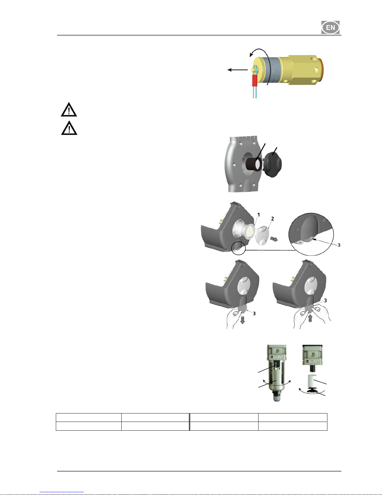
13.3. Safety valve check
(Fig.5)
When the compressor is operated for the first time,
make sure that the safety valve is working properly.
Turn screw of safety valve several rotations to the
left until the safety valve releases air. Let the
safety valve blow out for only a few seconds. Turn
screw to the right until it seats, closing the valve.
The safety valve must never be used for depressurizing the air tank. It could damage the
safety valve. The valve is set to the maximum permitted pressure by the manufacturer.
Adjustments are not permitted.
Warning! Compressed air can be dangerous. Wear eye protection when blowing air out.
13.4. Replacement of the input filter and prefilter
(Fig.6)
At the lid of the compressors crankcase is an
input filter (1) and prefilter (3).
Replacing of the input filter:
Hand pull the rubber stopper (2).
Remove used and dirty filter.
Input new filter and set rubber stopper.
Replacing of the prefilter:
Hand pull prefilter (3).
Replace old prefilter with new.
13.5. Replacement of filter element in filter
(Fig.7)
Loosen a safety-catch (1) on a filter regulator by pulling it down.
Turn the container slightly (2) and pull out.
Unbolt the filter holder (3).
Change the filter bed (4), bolt the filter holder.
Put the filter container on and secure it by turning it until the safety-
catch is fixed.
Filter Order number Filter insert Order number
AF 30-F02C 025200005
AF 30P-060S 5 m
025200061
Fig.5
2V
Fig.6
PLUS
1
2
4
3
Fig.7
INSTRUCTIONS FOR USE
NP-DK50 Plus, DK50 2V -MOBILE-MD-16_07-2015 - 14 - 07/2015
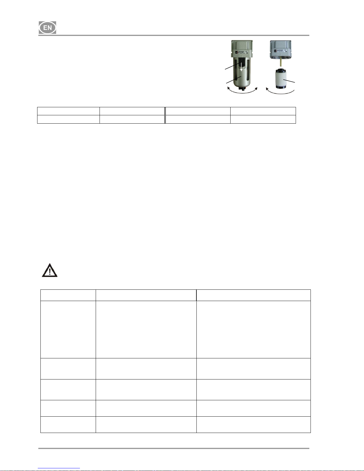
13.6. Replacement of filter element in mikrofilter
(Fig.8)
Loosen a safety-catch (1) on a micro filter by pulling it down.
Turn the container slightly (2) and pull out.
Unbolt the filter (3).
Change and bolt the filter bed.
Put the filter container on and secure it by turning it until the safetycatch is fixed.
14. STORAGE
When there is a predisposition that the compressor shall not be used for a prolonged time period, release air
pressure in the pressure tank. Switch off the compressor by switch (36) (Fig.3) and disconnect the appliance
from the mains.
15. DISPOSING OF THE APPLIANCE
• Disconnect the appliance from the mains.
• Release air pressure in the pressure tank.
• The components of the product are non-toxic.
• Dispose of the appliance following all environmental regulations.
16. REPAIR SERVICE
Guaranteed and post-guarantee repairs must be done by the manufacturer, its authorized representative, or
service personnel approved by the supplier.
The manufacturer reserves the right to make changes to the appliance without notice. Any changes made
will not affect the functional properties of the appliance.
17. SOLVING PROBLEMS
Caution! Before proceeding, depressurize the air tank to zero and disconnect the
appliance from the mains.
Troubleshooting can be performed only by qualified personnel.
FAILURE POSSIBLE CAUSE REMEDY
Compressor does not start No voltage in pressure switch Check voltage in socket
Check fuse – replace faulty one
Loosen terminal – tighten it
Check power cord – replace faulty one
Disconnected winding of motor, damaged thermal
protection
Faulty capacitor
Seizure of piston or another rotary part Pressure
switch does not switch on
Mains cord from compressor is not connected to
socket of the case.
Replace motor or re-wind it
Replace capacitor
Replace damaged parts
Check the function of pressure switch
Connect mains plug from compressor to socket in the
case (32) (Fig.3)
Compressor often
switches on
Air leak in pneumatic distribution system
Leaking check valve
Greater volume of condensed liquid in pressure
vessel
Check pneumatic distribution system – seal loose joint
Clean valve, replace seals, replace valve
Drain condensed liquid
(autodrain out of function)
Prolonged running of
compressor
Air leak in pneumatic distribution system
Worn piston ring
Contaminated filter
Defective solenoid valve
Check pneumatic distribution system – seal loose joint
Replace worn piston ring
Replace contaminated filter with the new one
Repair or change the valve
Compressor is noisy
(knocking, metal noises)
Damaged bearing of piston, piston rod, motor
bearing
Loose or cracked spring
Replace damaged bearing
Replace damaged spring
Dryer doesn´t dry
(condensed water in the
tank)
Contaminated filter or microfilter
Replace contaminated filter with the new one
Mikrofilter Order number Filter insert Order number
AFM 30-F02C 025200007
AFM 30P-060AS 0,3 m
025200076
Fig.8
2
3
1

GEBRAUCHSANWEISUNG
07/2015 - 15 - NP-DK50 Plus, DK50 2V -MOBILE-MD-16_07-2015
INHALT
GEBRAUCHSANWEISUNG ................................................................................................................. 16
WICHTIGE INFORMATIONEN ......................................................................................................... 16
1. CE KENNZEICHNUNG ............................................................................................................ 16
2. HINWEISE ................................................................................................................................ 16
3. WARNHINWEISE UND SYMBOLE ......................................................................................... 17
4. LAGER- UND TRANSPORTBEDINGUNGEN ......................................................................... 17
5. TECHNISCHE DATEN ............................................................................................................. 18
6. PRODUKTBESCHREIBUNG ................................................................................................... 19
7. FUNKTIONSBESCHREIBUNG ................................................................................................ 19
INSTALLATION ................................................................................................................................. 22
8. NUTZUNGSBEDINGUNGEN ................................................................................................... 22
9. PRODUKTINSTALLATION ...................................................................................................... 22
10. ERSTE INBETRIEBNAHME .................................................................................................... 24
BEDIENUNG ..................................................................................................................................... 24
11. EINSCHALTEN DES KOMPRESSORS ................................................................................... 24
WARTUNG ........................................................................................................................................ 25
12. WARTUNGSINTERVALLE ...................................................................................................... 25
13. WARTUNG ............................................................................................................................... 25
14. LAGERUNG ............................................................................................................................. 27
15. ENTSORGUNG DES GERÄTES ............................................................................................. 27
16. INFORMATIONEN ÜBER REPARATURBETRIEBE ............................................................... 27
17. FEHLERSUCHE UND FEHLERBEHEBUNG .......................................................................... 27
SERVICEHANDBUCH .......................................................................................................................... 41
18. SCHALTPLAN .......................................................................................................................... 41
19. VERZEICHNIS DER ERSATZTEILE ....................................................................................... 44
LIEFERUMFANG .................................................................................................................................. 60

GEBRAUCHSANWEISUNG
NP-DK50 Plus, DK50 2V -MOBILE-MD-16_07-2015 - 16 - 07/2015
GEBRAUCHSANWEISUNG
WICHTIGE INFORMATIONEN
1. CE KENNZEICHNUNG
Die Produkte mit der CE Kennzeichnung erfüllen die Sicherheitsrichtlinien (98/37/EEC - Council Directive of
Safety of Machinery, 73/23/EEC – Low-voltage directive) der Europäischen Union, EMC.
2. HINWEISE
2.1. Allgemeine Hinweise
Die Anleitung zur Installation, Bedienung und Wartung ist Bestandteil des Gerätes. Es ist notwendig, dass
sie in der Nähe des Aufstellungsortes des Gerätes immer zur Verfügung steht. Genaues Befolgen dieser
Anleitung ist eine Voraussetzung für ordnungsgemäße Nutzung des Gerätes und eine korrekte Bedienung.
Die Sicherheit des Bedienungspersonals und fehlerfreier Betrieb des Gerätes sind nur bei der Nutzung von
Originalgeräteteilen garantiert. Es dürfen nur Zubehör- und Ersatzteile genutzt werden, die in der
technischen Dokumentation aufgeführt oder ausdrücklich vom Hersteller erlaubt sind. Wird anderes
Zubehör genutzt, so kann der Hersteller keine Garantie für sicheren Betrieb und sichere Funktion
übernehmen.
Schäden, die durch Nutzen von anderem als vom Hersteller vorgeschriebenem Zubehör entstehen, sind
von der Gerätegarantie ausgeschlossen.
Der Hersteller übernimmt die Verantwortung für die Sicherheit, Zuverlässigkeit und Funktion des Gerätes
nur dann, wenn:
- Installation, Einstellungen, Veränderungen, Erweiterungen und Reparaturen vom Hersteller oder
vom Hersteller beauftragten Organisationen durchgeführt werden.
- die Nutzung des Gerätes in Übereinstimmung mit der Anleitung für Installation, Bedienung und
Wartung erfolgt.
Die Anleitung entspricht zum Zeitpunkt des Druckes der Ausführung des Gerätes und den zugehörigen
sicherheitstechnischen Vorschriften. Der Hersteller behält sich alle Rechte zum Schutz der aufgeführten
Schaltungen, Methoden und Bezeichnungen vor.
Die Übersetzung der Anleitung zur Installation, Bedienung und Wartung erfolgte im Einklang mit unseren
besten Kenntnissen. Bei Unklarheiten gilt die slowakische Text-Fassung.
2.2. Allgemeine Sicherheitshinweise
Beim Hersteller wurde das Gerät so entwickelt und gebaut, dass jedwede Gefahren bei dessen
bestimmungsgemäßen Gebrauch ausgeschlossen sind. Der Hersteller hält es für seine Pflicht die
nachstehenden Sicherheitsmaßnahmen wegen Ausschluss von allfälligen Beschädigungen zu beschreiben.
Bei dem Betrieb des Gerätes ist es notwendig, die Gesetze und regionalen Vorschriften, die im
Nutzungsgebiet gültig sind, zu befolgen. Im Interesse des sicheren Arbeitsablaufes sind der Betreiber und
der Nutzer für das Einhalten der Vorschriften verantwortlich.
Die Originalverpackung sollte für eine eventuelle Rückgabe des Gerätes aufbewahrt werden. Nur die
Originalverpackung garantiert optimalen Transportschutz des Gerätes. Falls eine Einsendung des Gerätes
während der Garantiezeit notwendig werden sollte, haftet der Hersteller nicht für Schäden, die auf eine
mangelhafte Verpackung zurückzuführen sind.
Der Nutzer muss mit der Gerätebedienung vertraut gemacht werden.
Das Produkt ist nicht bestimmt zum Betrieb in explosionsbedrohten Bereichen.
2.3. Sicherheitshinweise zum Schutz vor elektrischem Strom
Das Gerät darf nur an eine vorschriftsmäßig installierte Steckdose mit Schutzkontakt angeschlossen
werden.
Vor dem Anschluss des Gerätes muss kontrolliert werden, ob die auf dem Gerät angegebene
Netzspannung und Netzfrequenz mit den Werten des Versorgungsnetzes übereinstimmt.
Vor Inbetriebnahme ist das Gerät als auch die anzuschließenden Pressluft- und Elektroleitungen auf
eventuelle Beschädigungen zu überprüfen. Beschädigte elektrische und pneumatische Leitungen müssen
sofort ersetzt werden.
In gefährlichen Situationen oder bei technischen Störungen ist es nötig, das Gerät sofort vom Stromnetz
zu trennen.
Bei allen Arbeiten im Zusammenhang mit Reparatur und Wartung ist es notwendig, dass :
- das Gerät vom Stromnetz getrennt ist
- alle Druckleitungen entlüftet sind und Druckluft aus dem Druckbehälter abgelassen ist
Das Gerät darf nur durch technische Vertreter des Herstellers oder des Lieferanten installiert werden.
GEBRAUCHSANWEISUNG
07/2015 - 17 - NP-DK50 Plus, DK50 2V -MOBILE-MD-16_07-2015
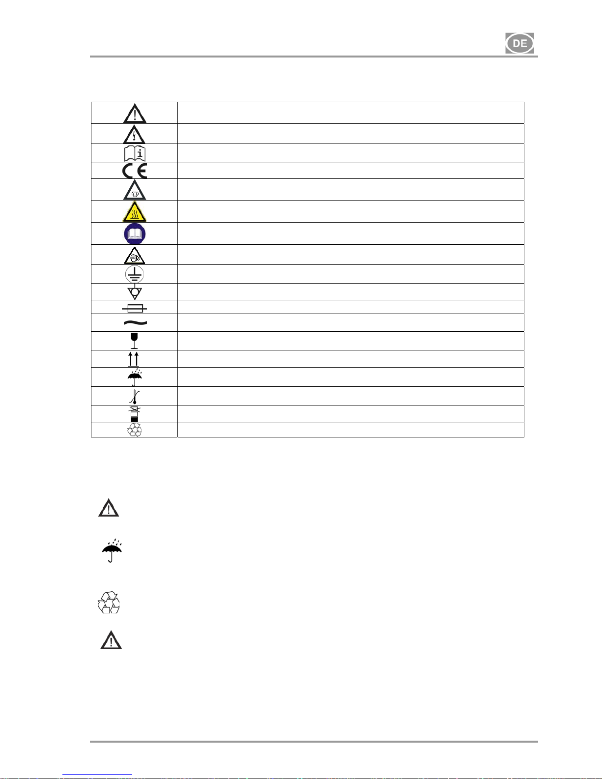
3. WARNHINWEISE UND SYMBOLE
In der Installations-, Bedienungs- und Instandhaltungsanleitung, auf der Verpackung und dem Produkt
werden für besonders wichtige Angaben folgende Bezeichnungen bzw. Zeichen benutzt:
Hinweise, Anweisungen und Verbote zur Vermeidung von Gesundheitsschäden
oder Sachschäden.
Warnung vor gefährlicher elektrischer Spannung!
Lese Bedienunganleitung.
CE – Markierung
Kompressor wird ferngesteuert und kann ohne Warnung starten.
Vorsicht! Heiße Oberfläche!
Hinweis: Die Bedienungsanleitung lesen.
Warnung: Die Wartungsarbeiten werden durchgeführt.
Anschluss des Schutzleiters
Klemme für äquipotentiellen Potentialausgleich
Sicherung
Wechselstrom
Verpackungshinweis – ZERBRECHLICH
Verpackungshinweis – DIESE SEITE OBEN
Verpackungshinweis – VOR NÄSSE SCHÜTZEN
Verpackungshinweis – TEMPERATURBESCHRÄNKUNGEN
Verpackungshinweis – BESCHRÄNKTE STAPELFÄHIGKEIT
Verpackungszeichen – RECYCLEBARES MATERIAL
4. LAGER- UND TRANSPORTBEDINGUNGEN
Der Kompressor wird vom Hersteller in einer Transportverpackung geliefert. Dadurch ist das Gerät gegen
Transportbeschädigungen gesichert.
Beim Transport nach Möglichkeit immer die Originalverpackung verwenden. Den
Kompressor nur in einer dem Symbol an der Packung entsprechenden Lage
transportieren!
Während des Transports und der Lagerung ist der Kompressor vor Feuchtigkeit,
Verunreinigungen und extremen Temperaturen zu schützen. Kompressoren in Originalpackung
müssen in warmen, trockenen und staubfreien Räumen lagern. Nicht in Räumen mit Chemikalien
lagern.
Nach Möglichkeit bewahren sie das Verpackungsmaterial auf. Falls dieses nicht möglich sein
sollte, entsorgen sie das Verpackungsmaterial bitte umweltschonend. Der Transportkarton kann
mit dem Altpapier entsorgt werden.
Der Kompressor darf nur drucklos transportiert werden. Vor dem Transport stets Druckluft
aus dem Druckbehälter und Druckschläuchen ablassen und zusätzlich Kondensat
entleeren.
Klimatische Bedingungen für Lagerung und Transport
Temperatur –25°C bis +55°C, 24 Std. bis +70°C
Relative Luftfeuchtigkeit 10% bis 90 % (ohne Kondensation)
Klimatische Betriebsbedingungen
Temperatur +5°C bis +40°C
Relative Luftfeuchtigkeit 70%
GEBRAUCHSANWEISUNG
NP-DK50 Plus, DK50 2V -MOBILE-MD-16_07-2015 - 18 - 07/2015
5. TECHNISCHE DATEN
(*) Gewünschte Kompressorausführung bitte bei der Bestellung angebe
(**) Es gilt für die Spannungsversion 115 / 60
- Die aus dem Membranlufttrockner M austretende Luft wird mit einem 0,3µm Filter gefiltert
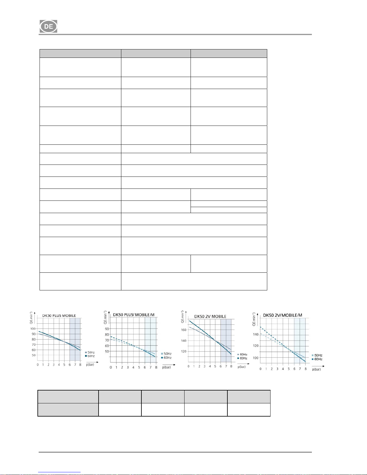
5.1. Luftfördervolumen – Wirkungsgradkorrektur für Höhenunterschiede
Luftfördervolumen–Korrektionstabelle
Höhe[Meter über dem
Meeresspiegel]
0–1500 1501–2500 2501–3500 3501–4500
Luftfördervolumen[l/min]
Luftfördervolumen
x1
Luftfördervolumen
x0,8
Luftfördervolumen
x0,71
Luftfördervolumen
x0,60
Luftfördervolumen – Wirkungsgrad bezieht sich auf die Bedingungen bei einer Höhe von 0 Meter über dem
Meeresspiegel: Temperatur: 20°C
Luftdruck: 101325 Pa
Relative Feuchtigkeit: 0 %
DK50 PLUS MOBILE DK50 2V MOBILE
Nennspannung /
Frequenz ( * )
V / Hz
230 / 50
230 / 60
115 / 60
230 / 50
230 / 60
115 / 60
Leistung des Kompressors bei 6
bar Überdruck Lit.min
-1
72 (50Hz)
70 (60Hz)
134 (50Hz)
132 (60Hz)
Leistung des Kompressors mit
Lufttrockner bei 6 bar Überdruck
Lit.min-1
60 (50Hz)
55 (60Hz)
105 (50Hz)
100 (60Hz)
Maximaler Nennstrom des
Kompressors
A
3,5
4,4
8,8
7,8
8,8
16,4
Maximaler Nennstrom mit
Lufttrockner
A
3,7
4,6
9
8,1
9,1
16,6
Leistung des Motors kW
0,55 1,1
Volumen des Druckbehälters
Lit.
25
Betriebsdruck des
Kompressoraggregats bar
6,0 – 8,0
Eingestellter Betriebsdruck des
Sicherheitsventils bar
12,0
Schallpegel L
pfA
[dB] 57 (50Hz)
59 (60Hz)
62 (50Hz)
64 (60Hz)
Betriebsart des Kompressors
dauerhaft S 1
dauerhaft S 1
aussetzend S 3-60% (**)
Betriebsart des Kompressors mit
Trockner
dauerhaft S 1
Abmessungen des Kompressors
B x T x H mm
580x700x1010
Abmessungen des Kompressors
im Karton
B x T x H mm
740x860x1200
Gewicht des Kompressors
/ des Kompressors mit Trockner
kg
100 / 105 104 / 110
Grad der Lufttrocknung mit
Trockner (atmosphärischer
Taupunkt)
-20°C
 Loading...