

EKOM DK50-10 Series, DK50-10 S/M, DK50-10 Z/K, DK50-10 S, DK50-10 Z User Manual
...
DK50-10
EN
User manual
DE
Benutzerhandbuch
FR
RU
Manuel de l’utilisateur
Руководство пользователя
PL
SK
Instrukcja obsługi
Návod na použitie
CS
Návod k použití


CONTENTS................................. 2
INHALT....................................... 30
SOMMAIRE................................ 58
СОДЕРЖАНИЕ.......................... 86
SPIS TREŚCI.............................. 114
OBSAH………............................. 142
OBSAH………............................. 170
Ed. - 1
08/2017 - 1 - NP-DK50-1_08-2017-MD

DK50-10
CONTENTS
IMPORTANT INFORMATION ................................................................................................................. 3
1. CE MARKING ............................................................................................................................ 3
2. WARNINGS ................................................................................................................................ 3
3. WARNINGS AND SYMBOLS ..................................................................................................... 4
4. STORAGE AND TRANSPORT ................................................................................................... 5
5. TECHNICAL DATA ..................................................................................................................... 6
6. PRODUCT DESCRIPTION ......................................................................................................... 9
7. PRODUCT FUNCTIONALITY ................................................................................................... 11
8. PNEUMATIC SCHEMATIC ....................................................................................................... 15
OPERATION .......................................................................................................................................... 16
9. SWITCHING THE COMPRESS OR ON ................................................................................... 16
INSTALLATION ..................................................................................................................................... 17
10. CONDITIONS FOR USE .......................................................................................................... 17
11. PLACEMENT OF THE COMPRESSOR ................................................................................... 18
12.PNEUMATIC CONNECTIONS ................................................................................................. 19
13. ELECTRICAL CONNECTIONS ................................................................................................ 19
14. CONNECTION SCHEMATIC .................................................................................................... 20
15. COMMISSIONING .................................................................................................................... 22
16. SWITCHING THE COMPRESSOR ON .................................................................................... 22
17. COMPRESSOR SHUT-DOWN ................................................................................................. 22
MAINTENANCE .................................................................................................................................... 23
18.EQUIPMENT MAINTENANCE ................................................................................................. 23
TROUBLESHOOTING .......................................................................................................................... 28
19.REPAIR SERVICE .................................................................................................................... 29
20.STORAGE ................................................................................................................................. 29
21.DISPOSING OF THE APPLIANCE ........................................................................................... 29
ANNEX ................................................................................................................................................ 198
22.INSTALLATION RECORD ...................................................................................................... 198
NP-DK50-1_08-2017-MD - 2 - 08/2017

DK50-10
IMPORTANT INFORMATION
1. CE MARKING
Products labeled with the CE mark of compliance meet the safety guidelines (93/42/EEC) of the European
Union.
2. WARNINGS
The product is designed and manufactured to be safe for the user and its surrounding environment when
used in the defined manner. Keep the following warnings in mind. This keeps risks to a minimum.
2.1. General warnings
The user manual aids in correct installation, operation and maintenance of the product. It is included with
the product and must be kept close to it at all times. Careful review of this manual will provide the
information necessary for correct operation of the product.
Original packaging should be kept for the return of the equipment. Only the original packaging ensures
protection of the equipment during transport. If it is necessary to return the product during the warranty
period, the manufacturer is not liable for damages caused by improper packaging.
This warranty does not cover damages originating from the use of accessories or consumables other
than those specified or suggested by the manufacturer.
The manufacturer only guarantees the safety, reliability and function of the equipment if:
- installation, new settings, changes, expansion and repairs are performed by the manufacturer or a
service provider authorized by the manufacturer.
- the product is used pursuant to the user manual.
The user manual corresponds to the configuration of the product and its compliance with applicable
safety and technical standards at the time of its printing. The manufacturer reserves all rights for the
protection of its configuration, methods and names.
Translation of the user manual is performed in accordance with the best available knowledge. The
Slovak version is to be used in the event of any uncertainties.
2.2. General safety warnings
The manufacturer designed and manufactured the product to mitigate all risks when used correctly. Please
note the following safety measures to mitigate residual risks.
Use and operation of the product must comply with all local codes and regulations. The operator and
user are responsible for following all appropriate regulations in the interests of performing work safely.
Only the use of original parts guarantees the safety of operating personnel and flawless operation of the
product itself. Only accessories and parts mentioned in the technical documentation or expressly
approved by the manufacturer may be used.
The operator must ensure the equipment is functioning correctly and safely before every use.
The user must fully understand the operation of the equipment.
Do not use the product in explosive environments.
The user must inform the supplier immediately if any problem occurs during use of the equipment.
08/2017 - 3 - NP-DK50-1_08-2017-MD
DK50-10
2.3. Electrical system safety warnings
The equipment may only be connected to a properly installed socket connected to earth (grounded).
Before the product is plugged in, make sure that the mains voltage and frequency stated on the product
are the same as the power mains.
Check for any damage to the connected compressed air system and electrical circuit before use.
Replace damaged pneumatic and electrical conductors immediately.
Immediately disconnect the product from the mains (remove the power cord from the socket) in
hazardous situations or when a technical malfunction occurs.
Ensure the following during any maintenance and repairs:
- the mains plug is pulled out from the power socket
- pressure is vented from the compressed air lines and the air tank
Only a qualified technician may install the product.
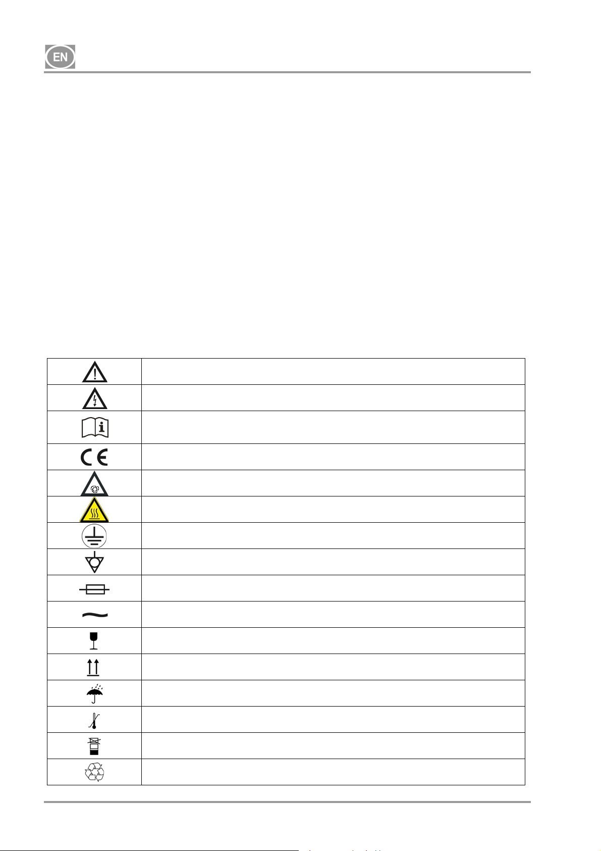
3. WARNINGS AND SYMBOLS
The following labels and symbols are used in the user manual and on the equipment and its packaging to
indicate important details and information:
Information, instructions and cautions for the prevention of damage to health or
materials
Caution! Dangerous electric voltage
Read the user manual!
CE mark of compliance
Caution! Hot surface
Compressor is remote-controlled and may start without warning
Earth (ground) connection
Terminal for ground connection
Fuse
Alternating current
Handling mark on package – FRAGILE
Handling mark on package – THIS SIDE UP
NP-DK50-1_08-2017-MD - 4 - 08/2017
Handling mark on package – KEEP DRY
Handling mark on package – TEMPERATURE LIMITATIONS
Handling mark on package – LIMITED STACKING
Mark on package – RECYCLABLE MATERIAL
DK50-10
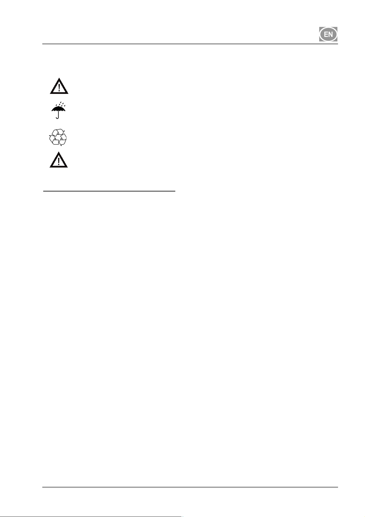
4. STORAGE AND TRANSPORT
The compressor is shipped in cardboard that protects the appliance from damage during transport.
Caution! For transport, always use the original packaging and secure the compressor in
the upright position.
Protect the compressor from humidity and extreme temperatures during transport and storage. A
compressor in its original packaging can be stored in a warm, dry and dust-free area. Do not
Ambient conditions for storage and transport
Products may only be stored and transported in vehicles that are free of any traces of volatile chemicals
under the following conditions:
store near any chemical substances.
Keep packaging material if possible. If not, please dispose of the packaging material in an
environmentally friendly way and recycle if possible.
Caution! Before moving or transporting the compressor, release all the air pressure from
the tank and hoses and drain the condensed water.
Temperature: –25°C to +55°C, 24 h at up to +70°C
Relative humidity: 10% to 90% (non-condensing)
08/2017 - 5 - NP-DK50-1_08-2017-MD
DK50-10
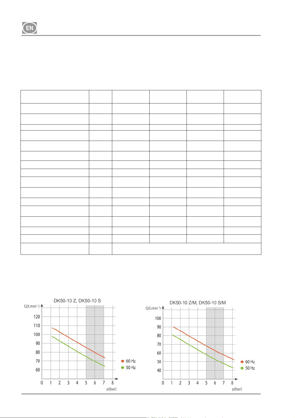
5. TECHNICAL DATA
Compressors are designed for dry and ventilated indoor environments with the following conditions:
Temperature : +5°C až +40°C,
Max. relative humidity.: 70%,
Max. absolute humidity. 15 g/m
Tab.1
3
5 – 7 bar
Nominal voltage / frequency (*) V / Hz
Output
at 5 bar
Working pressure (**) bar 5.0 – 7.0 5.0 – 7.0 5.0 – 7.0 5.0 – 7.0
Output with KJF-1
at 5 bar
Max. current A
Motor output kW 0.55 0.55 0.55 0.55
Air tank volume Lit. 10 10 10 10
Air quality – filtration
Maximum operating pressure of
safety valve
Noise level at 5 bar LpfA [dB]
Operating mode 100% - S 1 100% - S 1 100% - S 1 100% - S 1
PDP - drying performance at 7
bar
Time to fill air tank from 0 to 6
bar
Dimensions (net) w x d x h mm 485x350x553 580x440x655 544x350x553 649x440x655
Net weight kg 38 (***) 53 (***) 44
Configuration per
EN 60601-1
Lit.min-1
Lit.min-1
m
bar 8.0 8.0 8.0 8.0
- -
s
Type B, class I.
DK50-10 Z DK50-10 S DK50-10 Z/M
230 / 50/60
115 / 60
75 / 85
85
75 / 85
85
3.8 / 4.8
9.5
- - 0.3 0.3
65 / 66.5
66.5
50 / 44
44
230 / 50/60
115 / 60
75 / 85
85
75 / 85
85
3.8 / 4.8
9.5
49.5 / 51
51
50 / 44
44
230 / 50/60
115 / 60
58 / 68
68
- -
4.1 / 5.1
10
67 / 68.5
68.5
+3°C
70/60
60
DK50-10 S/M
230 / 50/60
115 / 60
58 / 68
68
4.1 / 5.1
10
51.5 / 53
53
+3°C
70/60
60
61
Notices:
(*) When ordering, state the version of compressor
(**) Range of pressure: consult with contractor
(***) Weight of compressors with a KJF1 unit _add 3 kg
(****) The permitted operating pressure of the safety valve can also be set to another value, e.g. 9 bar /
the setting shall be specified in the order.
NP-DK50-1_08-2017-MD - 6 - 08/2017
DK50-10
Tab. 2
6 – 8 bar
Nominal voltage / frequency (*) V / Hz
Output
at 6 bar
Working pressure (**) bar 6.0 – 8.0 6.0 – 8.0 6.0 – 8.0 6.0 – 8.0
Output with KJF-1
at 6 bar
Max. current A
Motor output kW 0.55 0.55 0.55 0.55
Air tank volume 10 10 10 10
Air quality – filtration
Maximum operating pressure of
safety valve
Noise level at 5 bar LpfA [dB]
Operating mode
PDP drying performance at 7
bar
Time to fill air tank from 0 to 7
bar
Dimensions (net) w x d x h mm 485x350x553 580x440x655 544x350x553 649x440x655
Net weight kg 38 (***) 53 (***) 44
Configuration per
EN 60601-1
Lit.min-1
Lit.min-1
m
bar 12.0 12.0 12.0 12.0
- -
s
DK50-10 Z DK50-10 S DK50-10 Z/M
230 / 50/60
115 / 60
70 / 80
80
70 / 80
80
3.9 / 4.9
9.8
- - 0.3 0.3
65 / 66.5
66.5
100% - S 1 100% - S 1 100% - S 1 100% - S 1
60 / 51
51
230 / 50/60
115 / 60
70 / 80
80
70 / 80
80
3.9 / 4.9
9.8
49.5 / 51
51
60/51
51
Type B, class I.
230 / 50/60
115 / 60
60 / 70
70
- -
4.1 / 5.1
10.2
67 / 68.5
68.5
+3°C
72/61
61
DK50-10 S/M
230 / 50/60
115 / 60
60 / 70
70
4.1 / 5.1
10.2
51.5 / 53
53
+3°C
72/61
61
61
Notices:
(*) When ordering, state the version of compressor
(**) Range of pressure: consult with contractor
(***) Weight of compressors with a KJF1 unit _add 3 kg
(****) The permitted operating pressure of the safety valve can also be set to another value, e.g. 9 bar /
the setting shall be specified in the order.
08/2017 - 7 - NP-DK50-1_08-2017-MD

DK50-10
Tab. 3
8 – 10 bar
Nominal voltage / frequency (*) V / Hz
Output
at 8 bar
Working pressure (**) bar 8.0 – 10.0 8.0 – 10.0 8.0 – 10.0 8.0 – 10.0
Output with KJF-1
at 8 bar
Max. current A
Motor output kW 0.55 0.55 0.55 0.55
Air tank volume 10 10 10 10
Air quality – filtration
Maximum operating pressure of
safety valve
Noise level at 5 bar LpfA [dB]
Operating mode
PDP drying performance at 7
bar
Time to fill air tank from 0 to 9
bar
Dimensions (net) w x d x h mm 485x350x553 580x440x655 544x350x553 649x440x655
Net weight kg 38 (***) 53 (***) 44
Configuration per
EN 60601-1
Lit.min-1
Lit.min-1
m
bar 12.0 12.0 12.0 12.0
- -
s
DK50-10 Z DK50-10 S DK50-10 Z/M
230 / 50/60
115 / 60
60 / 70
70
60 / 70
70
4.1 / 5.1
10.2
- - 0.3 0.3
65 / 66.5
66.5
100% - S 1 100% - S 1 100% - S 1 100% - S 1
85/75
75
230 / 50/60
115 / 60
60 / 70
70
60 / 70
70
4.1 / 5.1
10.2
49.5 / 51
51
85/75
75
Type B, class I.
230 / 50/60
115 / 60
50 / 60
60
- -
4. / 5.3
10.5
67 / 68.5
68.5
+3°C
96/82
82
DK50-10 S/M
230 / 50/60
115 / 60
50 / 60
60
4.4 / 5.4
10.5
51.5 / 53
53
+3°C
96/82
82
61
Notices:
(*) When ordering, state the version of compressor
(**) Range of pressure: consult with contractor
(***) Weight of compressors with a KJF1 unit _add 3 kg
(****) The permitted operating pressure of the safety valve can also be set to another value, e.g. 9 bar /
the setting shall be specified in the order.
NP-DK50-1_08-2017-MD - 8 - 08/2017
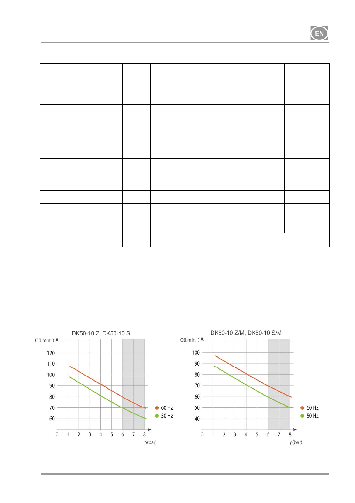
DK50-10
5.1. Free air delivery (FAD) correction due to elevation
FAD correction table
Elevation [mamsl] 0 - 1500 1501 - 2500 2501 - 3500 3501 - 4500
FAD [l/min] FAD x 1 FAD x 0.8 FAD x 0.71 FAD x 0.60
FAD output related to conditions:
Elevation: 0 MASL Temperature : 20°C
Atmospheric pressure : 101325 Pa Relative humidity : 0%
6. PRODUCT DESCRIPTION
6.1. Model variations and their uses
The compressor is used as a source of clean, oil-free compressed air to power dental equipment,
instruments and devices in laboratories where the parameters and properties of the compressed air are
suitable to the specific application.
Compressed air supplied by the compressor is unsuitable for use with artificial lung
ventilation devices without further filtration
Any use of the equipment outside the framework defined herein is considered inappropriate use. The
manufacturer is not liable for any damages or injury occurring as a result of inappropriate use.
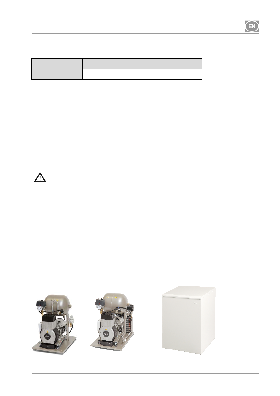
6.2. Description
Compressor models are designed for the following uses:
DK50-10 Z compressor - a base-mounted compressor for stand-alone installation in a given space
DK50-10 Z/K compressor - a base-mounted compressor with a condensate and filtration unit (KJF1)
DK50-10 Z/M compressor - a base-mounted compressor with an air dryer
DK50-10 S compressor - an enclosed compressor with effective noise dampening for in-office installations
DK50-10 S/K compressor - an enclosed compressor with a condensate and filtration unit (KJF1)
DK50-10 S/M compressor - an enclosed compressor with an air dryer
DK50-10 Z
DK50-10 Z/M
DK50-10 S
DK50-10 S/M
08/2017 - 9 - NP-DK50-1_08-2017-MD
DK50-10
6.3. Accessories
Accessories not included in the standard order must be ordered separately!
6.3.1 Automatic condensate drain
The automatic condensate drain (AOK) automatically drains condensate from the compressor’s air tank
based on a pre-set time interval. The condensate drain (AOK) is a suitable accessory for compressor
models without dryers.
6.3.2 Set of filters
Compressors may be equipped with a set of filters on the compressed air outlet if specified. The set of filters
may be equipped with a pressure regulator. Sets of filters are suitable accessories for all the compressors
specified above.
NOTE : If a higher level of air filtration is required, this specification must be agreed upon with the supplier
and made clear in the order.
Level of filtration Pressure regulator Kit article no.
SET OF
FILTERS
6.3.3 Condensation and filtration unit (KJF)
The compressor may additionally be fitted with a condensation and filtration unit (KJF-1 or KJFR-1). The
KJF-1 or KJFR-1 ensure that the compressed air from the air tank is cooled in the cooler and the
condensate is captured in the filter and automatically separated from the compressed air circuit. The
compressed air is filtered at the same time.
Condensation and
filtration unit
KJF-1
KJFR-1 Yes 450001011-002
-
5µm 604013233-000
0,3µm
0,01µm 604013235-000
Level of filtration
5µm
Yes
No
Pressure
regulator
No 450001011-001
604013245-000
604013234-000
Kit article no.
NP-DK50-1_08-2017-MD - 10 - 08/2017
DK50-10
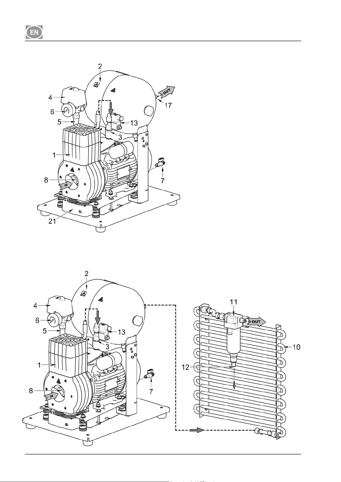
7. PRODUCT FUNCTIONALITY
Compressor (Fig. 1)
The compressor aggregate (1) draws in air through an inlet filter (8) and compresses it through a check
valve (3) into an air tank (2) from which the appliance draws compressed air. If the pressure in the air tank
drops to the switching pressure, the pressure switch (4) turns on the compressor and the compressor
supplies compressed air to the air tank until it reaches the switch off pressure, at which time the compressor
switches off. The pressure hose is vented through the relief solenoid valve (13) once the compressor unit is
shut off. The safety valve (5) prevents the pressure in the air tank from rising above the maximum allowed
value. The drain valve (7) drains condensate from the air tank. Compressed, oil-free filtered air is stored in
the air tank ready for use.
Condensate must be drained from the air tank at regular intervals (see Chapter 18).
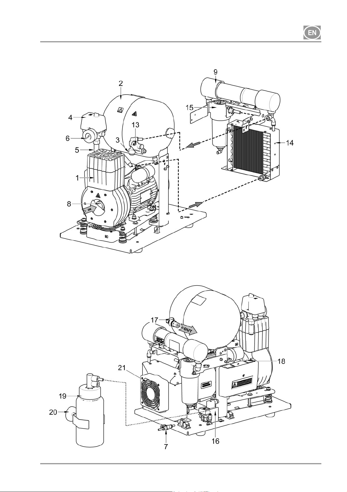
Compressor with membrane dryer. (Fig. 3)
The compressor aggregate (1) draws in air through an inlet filter (8) and compresses it, feeding it to the
cooler (14) through the filter (15) to the dryer (9) and the dry, clean air is then fed through the check valve
(3) into the air tank (2). A portion of the air bypasses the dryer with the captured moisture, which is
manifested as a gentle stream of air along the body of the dryer (9). Condensate from the filter is
automatically drained at regular intervals into the vessel via the condensate drain solenoid valve (16). The
dryer ensures continuous drying of the compressed air. The drain valve (7) drains condensate from the air
tank when drying performance is checked. Compressed, oil-free filtered air is stored in the air tank ready for
use.
The compressor with dryer requires no operator. The pressure vessel does not need to be drained.
Compressor with condensate and filtration unit (Fig. 2)
The compressor aggregate (1) draws in air through an inlet filter (8) and compresses it through a check
valve (3) into an air tank (2). Compressed air from the air tank flows through a cooler (10) that cools the
compressed air. The condensed moisture is trapped in the filter (11) and automatically separates as
condensate (12) into the vessel. Compressed, oil-free filtered air is ready for use.
Condensate must be drained from the air tank at regular intervals (see Chapter 18).
Compressor enclosure
The soundproof enclosure is compact and allows sufficient cooling air exchange. The design makes it
suitable for in-office installations in a way that blends in with other furniture. The fan under the compressor
aggregate ensures sufficient cooling for the compressor and runs with the compressor motor or when the
temperature switch is activated at temperatures above 40 °C.
Make sure that nothing impedes the free flow of air under and around the compressor.
Never cover the hot air outlet on the top back side of the case.
If placing the compressor on a soft floor such as carpet, create space for ventilation
between the base and floor or the box and floor, e.g. underpin the footings with hard
pads.
The 10 bar compressor model is equipped with an hour meter (Fig. 4).
08/2017 - 11 - NP-DK50-1_08-2017-MD
DK50-10
Fig. 1 - DK50-10 Z - Compressor
Description for Figures 1-4
1. Compressor aggregate
2. Air tank
3. Check valve
4. Pressure switch
5. Safety valve
6. Pressure gauge
7. Drain valve
8. Inlet filter
9. Dryer
10. Pipe cooler
11. Filter
12. Condensate outlet
13. Solenoid valve
14. Dryer cooler
15. Filter
16. Valve with timer
17. Compressed air outlet
18. Breaker switch
19. Vessel
20. Magnetic bracket
21. Fan
22. Switch
23. Hour Meter
24. Connector
25. Box fan
Fig. 2 – DK50-10 Z/K - Compressor with KJF1 condensate and filtration unit
NP-DK50-1_08-2017-MD - 12 - 08/2017
DK50-10
Fig. 3 - DK50-10 Z/M - Compressor with dryer
08/2017 - 13 - NP-DK50-1_08-2017-MD
DK50-10
Fig. 4 - Compressor DK50-10 S/M - 10bar
NP-DK50-1_08-2017-MD - 14 - 08/2017
DK50-10
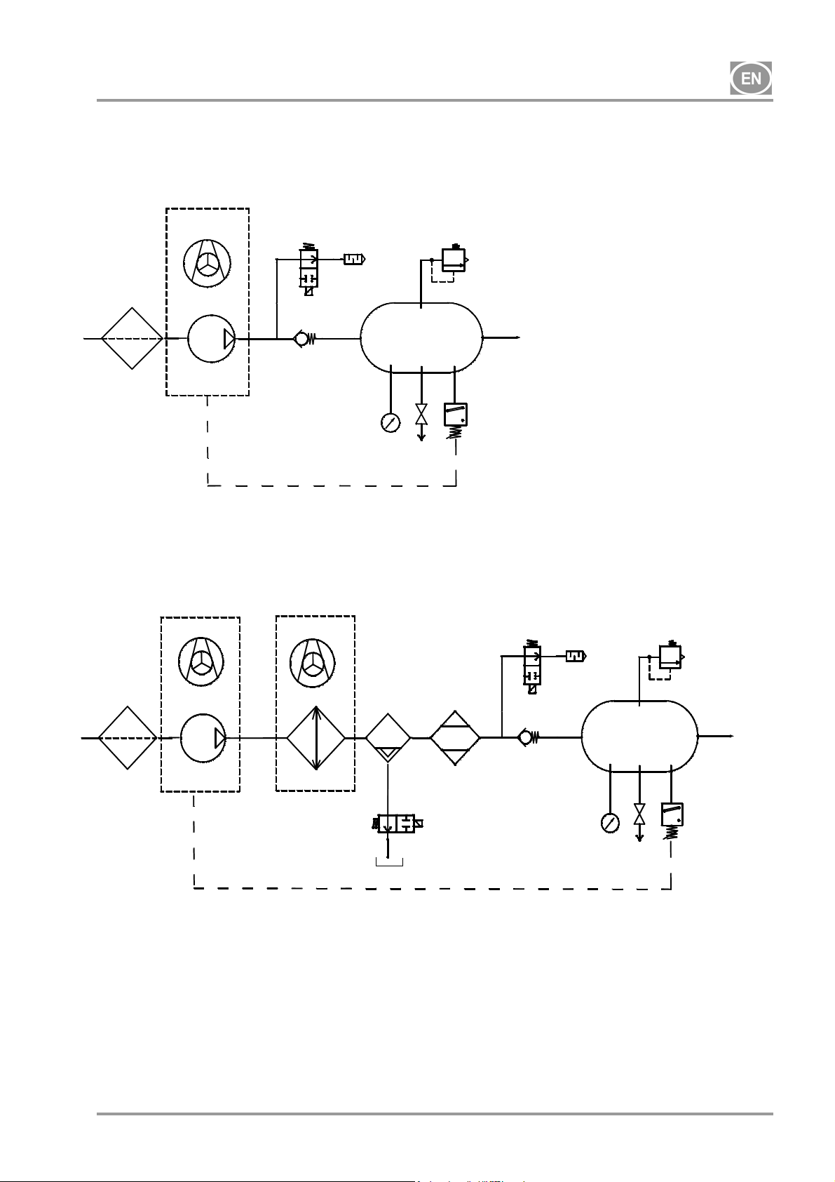
8. PNEUMATIC SCHEMATIC
DK50-10Z, DK50-10S
1
DK50-10Z/M, DK50-10S/M
1
Legend for compressed air schematics
1. Inlet filter
2. Compressor
3. Fan
4. Relief valve
5. Noise muffler
6. Check valve
7. Pressure gauge
8. Pressure switch
3
4
2
3
2
6
3
12
14
9
8
4
6
5
10
11
7
9
8
5
10
11
7
13
16
15
9. Safety valve
10. Air tank
11. Drain valve
12. Cooler
13. Coalescence filter
14. Membrane dryer
15. Condensate tank
16. Condensate drain solenoid valve
08/2017 - 15 - NP-DK50-1_08-2017-MD
DK50-10
OPERATION
In case of emergency, disconnect the compressor from the mains (pull out the mains
plug).
The compressor has hot surfaces.
Burns or fire may result if contact is made.
During prolonged operation of the compressor, the temperature in the box may increase
The working pressure settings for the pressure switch set by the manufacturer cannot be changed.
Compressor operation at a working pressure below the switching pressure indicates high air usage by the
attached appliance (see the Malfunctions chapter)
9. SWITCHING THE COMPRESSOR ON
to over 40°C. At this point the cooling fan automatically switches on. After cooling the
space to under 32°C, the ventilator switches off.
Automatic start: when pressure in the tank drops to the pressure switch’s lower limit
level, the compressor automatically switches on. The compressor automatically switches
off after reaching the pressure switch’s upper limit level.
Required drying performance can only be achieved when following the defined operating
conditions!
Drying performance will decline and the achieved dew point will drop if the dryer is
operated at any pressure below the minimum working pressure!
The dryer will suffer damage if operated at ambient temperatures above the maximum
working temperature!
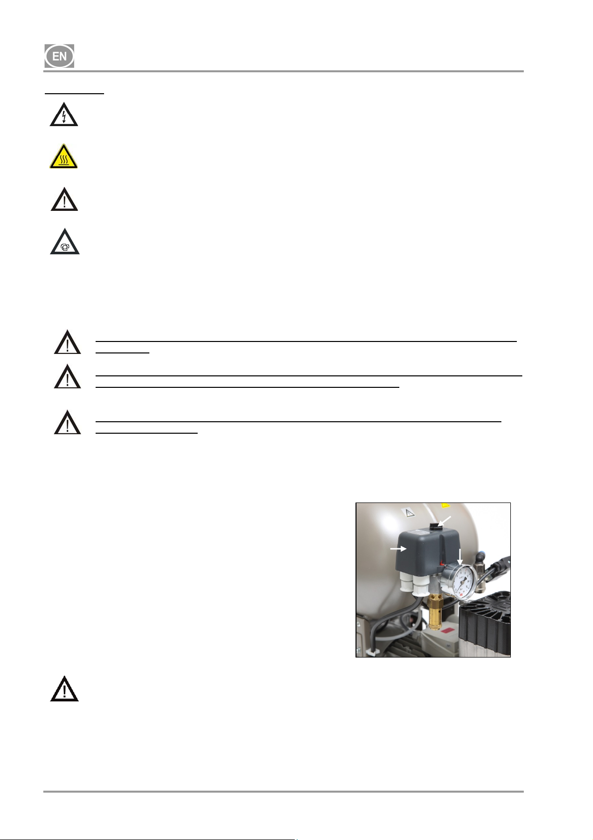
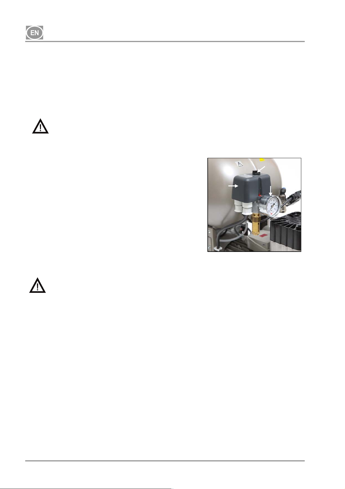
(Fig. 5)
Turn the compressor on at the pressure switch (2) by rotating the
main switch (3) to the “I” position. Check the position of the breaker
switch, it must be in the “I” position. If it is in the “0” position, turn
the switch to the “I” position (Fig.3 – position 18). The switch (Fig. 4
– position 22) in the case of DK50-10 S/M 10bar compressors is on
the front side of the enclosure; the indicator lights up green. The
compressor switches on and begins to fill the air tank until the
pressure reaches the switching pressure and the pressure switch
turns the compressor off. The compressor then operates in
automatic mode and is controlled by the on and off pressure
settings on the pressure switch based on compressed air usage.
This pressure may be monitored on the pressure gauge (5). A
tolerance of 10% is acceptable. The pressure in the air tank may
not exceed the permitted operating pressure.
Changing the switching pressures on the pressure
switch is prohibited on any compressor.
The pressure switch (2) has been set by the manufacturer and further setting of switching on and off
pressure may be carried out only by a qualified expert trained by the manufacturer.
2
Fig. 8
Fig.5
3
5
NP-DK50-1_08-2017-MD - 16 - 08/2017

DK50-10
INSTALLATION
10. CONDITIONS FOR USE
Compressors may only be installed and operating in dry, well-ventilated and clean environments with
environmental parameters that meet the requirements specified in Chapter 5, Technical data. The
compressor must be installed so that it is accessible at all times for operating and maintenance. Please
ensure that the nameplate on the device is readily accessible.
The compressor must stand on a flat, sufficiently stable base (be aware of the weight of the compressor,
see Chapter 5, Technical data).
Compressors may not be operated outdoors or in otherwise wet or damp environments. Do not use the
compressor in the presence of explosive gases, dust or flammable liquids.
Before connecting the compressor to medical equipment, the supplier must confirm that it meets all
requirements for its use. Refer to the technical data of the product for this purpose. When a unit is to be
built-in, classification and evaluation of compatibility must be done by the manufacturer or supplier of the
product to be used.
Any use other than that described in this manual is not covered by the guarantee, and the manufacturer is
not liable for any damages that may result. The operator/user assumes all risk.
Only a qualified professional may install the compressor and place it into operation for
the first time. This professional is obliged to train operating staff as to the use and
maintenance of the equipment. Installation and training of all operators shall be confirmed
by the installer’s signature on the certificate of installation.
Prior to installation, ensure that the compressor is free of all transport packaging and
stabilizers to avoid any risk of damage to the product.
Caution! When in operation, the compressor is hot. Burns or fire may result if contact is
made by the operator or any flammable material.
Ambient operating conditions
Temperature: +5°C to +40°C,
Max. relative humidity: 70%,
Max. absolute humidity: 15 g/m
3
.
08/2017 - 17 - NP-DK50-1_08-2017-MD
DK50-10
11. PLACEMENT OF THE COMPRESSOR
The equipment shall only be installed by a qualified professional.
Unwrap the compressor from the packaging.
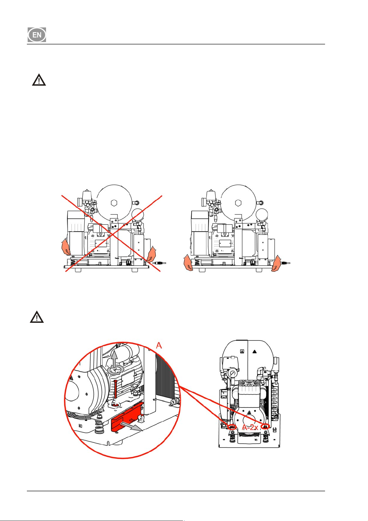
11.1. Handling and releasing the compressor
Position the compressor at the site of future operation (Fig. 6)
Fig.6
Remove the transport stabilisers from the aggregates. (Fig. 7)
Remove all devices used to secure the compressors once the compressor set has been installed
and mounted at the site of final installation!
Fig.7
NP-DK50-1_08-2017-MD - 18 - 08/2017
DK50-10
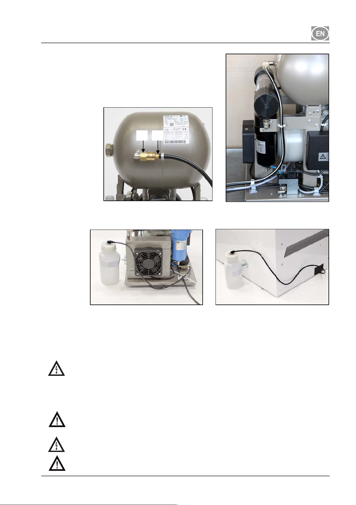
12. PNEUMATIC CONNECTIONS
12.1. Compressed air outlet (Fig. 8)
Connect a pressure hose terminated at one end with a sliding
quick connector (1) to the compressed air outlet (2) on the
compressor and connect the hose to the compressed air
system or directly to the appliance, in this case dental
equipment.
Fig.8
12.2. Condensate outlet (Fig. 9)
2 1
Connect the condensate drain hose to the condensate vessel on compressors with dryers.
Fig. 9
Route the hose through the opening in the rear wall of the enclosure for other compressors (without
dryers).
13. ELECTRICAL CONNECTIONS
The product is equipped with a grounded plug. Insert the mains plug into a rated mains socket.
Ensure full compliance with all local electrical codes. The mains voltage and frequency
must comply with the data stated on the device's label.
Keep the socket easily accessible to ensure that in an emergency the appliance can be safely
disconnected from the mains.
Connection to the power distribution box must be max.16 A.
The enclosure for the DK50-10S/M 10 bar model compressor is equipped with a cooling fan
and a switch. The enclosure must be connected using the provided cord with connector to the
matching connector on the compressor’s electrical panel. (Fig. 4)
Ensure the electrical cable does not touch hot compressor components. Risk of electric
shock!
If any electrical cord or air hose is damaged it must be replaced immediately.
08/2017 - 19 - NP-DK50-1_08-2017-MD

DK50-10
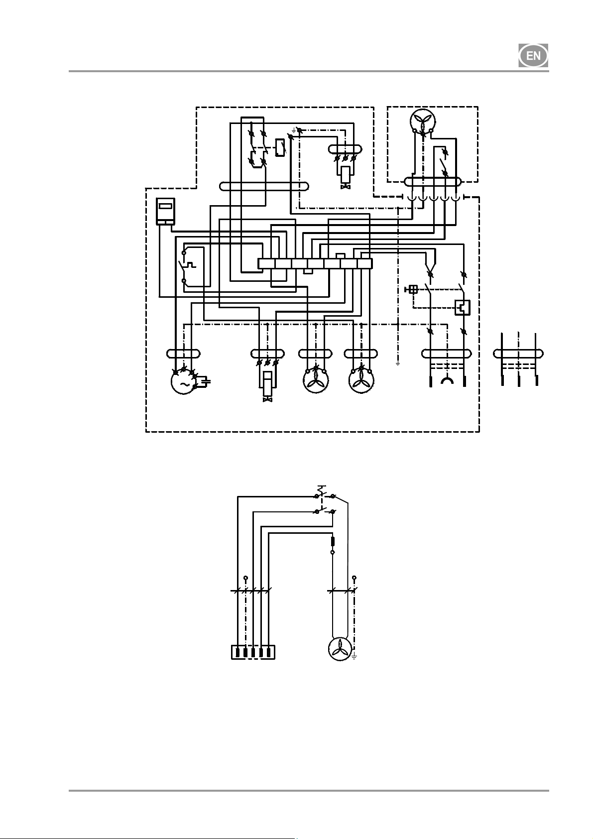
14. CONNECTION SCHEMATIC
DK50-10 Z, DK50-10 S - 5-7bar, 6-8, 8-10 bar
1/N/PE ~ 115V / 60 Hz
~ 230V / 50/60 Hz
00000
bk bu
P1*
bk
B2
5G1
bn gy
40°C
bk
3G1
1
bk-1bk-2
M
C1
M1
DK50-10 Z/M, DK50-10 S/M 5-7bar, 6-8 bar
1/N/PE ~ 115V / 60 Hz
~ 230V / 50/60 Hz
5G1
bn gy
bk
B2
40°C
bk
3G1
M
1
M1
bk-1bk-2
3G0,75
C1
X1
X1
bk
1
bk
bn
B1
p >
bu
2
U
B1
p >
bu
2
1
T
U
bu bu
bn
3G0,5
M4
N
3G0,75
3G0,75
N
bu
N
E2
bn
M3
* - only for 8-10bar version
bu bk
bu
P1
P2
F1
gnye
4
8
bu bu
bn
3G0,5
bn
bu
E1
3G1,5
CE
gnye
PE
bn
UN
gnye
bu bn
3G1,5
UK
PE
UN
M3
bu bk
F1
3G1,5
bu
bu
CE
P2
8
gnye
PE
P1
4
gnye
bn
UN
bu bn
3G1,5
PE
UN
UK
N
gnye
bu
bn
3G0,5
E1
NP-DK50-1_08-2017-MD - 20 - 08/2017
DK50-10
DK50-10 Z/M, DK50-10 S/M - 8-10 bar
1/N/PE ~ 230V 50..60Hz
Box for DK50-10 S/M - 10bar
Legend for electrical schematics
~ 115V 60Hz
bn gy
5G1
00000
P1
bkbu
bk
3G1
B2
40°C
bk
bk-1bk-2
M
1
X1
bn
3G0,75
C1
M1
* - only for DK50-10 Z/M version
1/N/PE ~ 230V 50..60Hz
bn
bu
PE
5G1
-X10
1
N23PE
M1 Compressor motor
E1 Compressor fan
E2 Dryer fan
M3 Solenoid valve
B2 Temperature switch
E3,E10 Box fan
X10, X2 Connector
B1
p >
3G0,75
bk
bu
2
1
U
U
bn
bu
M3
N
N
N
*
gnye
bu bu bu
T
bk
gy
M4
3G0,5
-S10
bn
E2
2
2a
1
1a
1
bn
3G0.5
3G0,5
bu
bu
bn
E1
PE
-E10
C1 Capacitor
B1 Pressure switch
X1 Terminal strip
F1 Protected switch
M4 Condensate drain valve
P1 Hour meter
S1 Switch
2
E3
S1
gy
5G1
bu
N
bu
F1
bu bk
3G1,5
bk
bn
1
32
bk
bk
bk
X2
bu
P1
P2
4
8
gnye
PE
bn
UN
bu bn
3G1,5
CE UK
1
1 - Compessor
2 - Box
gnye
PE
UN
08/2017 - 21 - NP-DK50-1_08-2017-MD
DK50-10
15. COMMISSIONING
(Fig. 10)
Make sure all transport stabilizers were removed.
Check that all pressurized air line connections are secure.
Check to ensure power is connected correctly to the compressor.
Check the position of the main switch; it should be in the “I” position; if the switch remains in the “0”
position, turn the main switch to the “I” position. (Fig. 3)
Check to see if the DK50-10S/M enclosure (8-10 bar models only) is connected to the compressor using
the cable with the connector.
The compressor is not equipped with a backup power supply.
16. SWITCHING THE COMPRESSOR ON
(Fig. 10)
3
Turn the compressor on using the pressure switch (2) by rotating
the selector (3) to the “I” position. Check the position of the
breaker switch, it must be in the “I” position. If it is in the “0”
position, turn the switch to the “I” position (Fig.3 – position 18).
2
5
The switch (Fig. 4 – position 22) in the case of DK50-10S/M 10bar
compressors is on the front side of the enclosure; the indicator
lights up green. The compressor switches on and begins to fill the
air tank until the pressure reaches the switching pressure and the
pressure switch turns the compressor off. The compressor then
operates in automatic mode and is controlled by the on and off
pressure settings on the pressure switch based on compressed air
usage. This pressure may be monitored on the pressure gauge
(5). A tolerance of 10% is acceptable. The pressure in the air
tank may not exceed the permitted operating pressure.
Fig. 10
Adjustments to the pressure range on the compressor’s pressure switch are prohibited.
The pressure switch (2) was set up by the manufacturer and only a qualified technician
trained by the manufacturer may make any changes to its settings.
Compressor – when first started and placed into service, the compressor fills the air tank until the switching
pressure and the pressure switch turn off the compressor. The compressor operates in automatic mode,
switched on and off by the pressure switch, depending on compressed air usage.
Compressor with dryer – the compressor operates in the same manner as above, only the compressed air
passes through a cooler to remove moisture from the compressed air.
Compressor with a condensate and filtration unit (KJF-1) - during usage by the appliance, the
compressed air passes through the KJF-1 unit, where the air is cooled, filtered and condensed liquid is
captured and automatically drained into a vessel.
17. COMPRESSOR SHUT-DOWN
Compressor shut-down for service or any other reason is performed at the pressure switch (2) by turning the
selector (3) to the “0” position and pulling the mains plug from the socket. This disconnects the
compressor from power. Then open the drain valve (Fig. 1) to vent the pressure in the air tank to zero.
NP-DK50-1_08-2017-MD - 22 - 08/2017
DK50-10
MAINTENANCE
18. EQUIPMENT MAINTENANCE
Warning!
The operator shall ensure completion of repeated testing of the equipment at least once every 24
months (EN 62353) or at intervals defined by applicable national legal regulations. A record of these
test results shall be completed (e.g. per EN 62353, Annex G) together with the measurement
methods.
The equipment has been designed and manufactured to keep maintenance to a minimum. The following
work must be performed to preserve the proper and reliable operation of the compressor.
Before starting compressor maintenance work, check to ensure the compressor is
disconnected from the appliance to ensure the person using the appliance is not at risk
and there is no risk of any other material damages!
Aggregate components (head, cylinder, pressure hose, etc.) are very hot during and
shortly after compressor operation – do not touch these components!
Repair work beyond normal maintenance can be performed only by qualified personnel or
he manufacturer’s representative.
Use only spareparts and accessories approved by the manufacturer.
Wear eye protection, i.e. goggles, when venting compressed air from the compressed air
circuit (air tank).
The work below may only be performed by trained personnel as follows:
BEFORE STARTING ANY MAINTENANCE WORK, IT IS NECESSARY to switch the
compressor off, disconnect it from the mains (pull out the mains plug) and vent the
compressed air from the air tank.
The 10 bar compressor model is equipped with an hour meter (Fig. 4), used to check the total hours of
operation.
08/2017 - 23 - NP-DK50-1_08-2017-MD
DK50-10
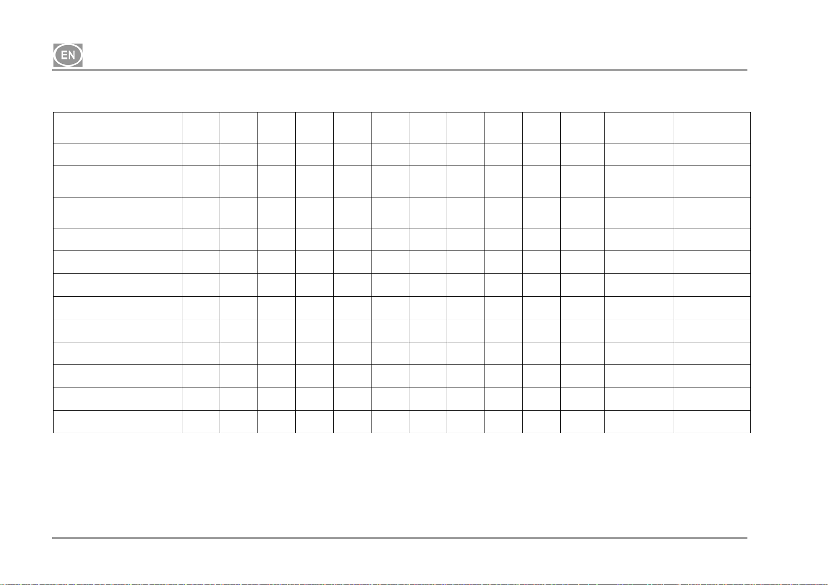
18.1. Maintenance intervals
Time interval
once
a day
once
a week
once
a year
once
every 2
years
2000 4000 6000 8000 10000 12000 Chapter
Set of spare
parts
Performed by
Produkto operational checks
Drain condensate from the air
tank )**
- At high humidity
Drain condensate from the air
tank )**
- At normal humidity
Product function check x
Leak check connections and
inspect equipment
Inspection of electrical
connections
Cooler and fan check
Filter element replacement
in the dryer filter
Filter element replacement in
theKJF-1
Safety valve check x
Conduct a “repeated test” per
EN 62353
Aggregate inlet filter
replacement )*
x 18.2 -
x
x
x
x
x
x
x
x 18 -
x x
)* data is presented in hours; if not possible, then the data is considered in years
)** only for compressors without dryers
18.5 - user
18.5 - user
7 - user
18.3 -
18.4 -
18.10 -
18.8 025200304-000
18.9 025200061-000
18.6 -
x x 18.7 025200126-000
user
qualified
professional
qualified
professional
qualified
professional
qualified
professional
qualified
professional
qualified
professional
qualified
professional
qualified
professional
NP-DK50-1_08-2017-MD - 24 - 08/2017

DK50-10
18.2. Operational checks
Check aggregate condition – the aggregates should be operating normally without excessive vibration
or noise. Troubleshoot any problem or call in service personnel if trouble is detected
Visually inspect fan operation – the fans must be operating when the aggregates are running.
Troubleshoot any problem or call in service personnel if trouble is detected
Check to ensure the power cable and pneumatic hoses are undamaged. Replace damaged
components or call in service personnel.
Check the ambient temperature – the ambient temperature must be below the temperature limit (40
°C). Cool the space if the temperature is high.
On the compressor with dryer – open the plug on the condensate vessel to drain the condensate
18.3. Leak check compressed air connections and inspect the equipment
Leak check:
Leak check the compressed air lines when the compressor is running and under pressure (not during
regeneration venting).
A Use a leak analyser or soapy water to check all joints and connections for leaks. Tighten or reseal
the connection where leaks are found.
Equipment inspection:
Check the condition of the compressor aggregate for normal operation and noise levels.
Fan operation check - the fans must be running during the defined compressor work cycles
Check of temperature switch operation (B2) – heat the temperature switch to a temperature above
40°C (e.g. using a heat gun, being careful not to warp any plastic pieces nearby). Fan EV1 (and EV2
for a compressor with dryer) will start up once the temperature reaches 40°C so long as power is
connected to the compressor.
Check filter condition – the filters must be undamaged and sufficiently clean.
Check the condition of the aggregate itself and ensure there is no contamination inside the crankcase
or play in the crankshaft
Replace any defective parts as needed.
18.4. Inspection of electrical connections
Check all electrical connections on the equipment with the mains disconnected!
Inspection
Check the mechanical function of the main switch.
Check to ensure the power cable and connected wires are undamaged.
Visually inspect the connection of individual cables to the terminal strip.
Inspect all screw terminals for the protective green and yellow PE grounding conductor.
08/2017 - 25 - NP-DK50-1_08-2017-MD
g
DK50-10
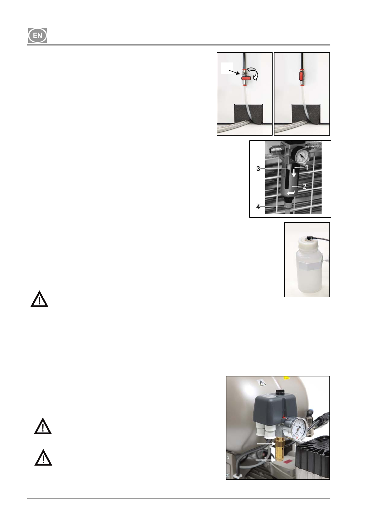
18.5. Condensation drain valve
Compressors (Fig. 11)
1
Draining the condensate from the pressure vessel is
recommended during regular operation. Switch off the
compressor at the mains and lower the pressure to a maximum
of 1 bar, for instance, by venting air through the connected
equipment. Place the hose with the drain valve into a vessel
prepared in advance and open the drain valve (1) to remove the
condensate from the tank.
Fig.11
Compressors with condensation and filtration unit (Fig.12)
During regular use, condensation is automatically released via
the release valve of the condensation unit filter. To check that
the automatic drain is working properly, open the valve (4) of the
drain vessel (2) by turning to the left. Release a small amount of
condensate from the vessel. Close the valve (4) by turning to
the right.
Both types of compressors may be equipped with an automatic
Fig.12
condensate drain on the air tank condensate drain to allow the
condensate to drain without operator intervention (see the
Scope of Delivery – Accessories chapter).
Compressors with air dryer (Fig.13)
Condensate from compressors with air dryers is automatically
drained into a vessel. The vessel must be drained regularly, see
Chapter 18.2
Fig.13
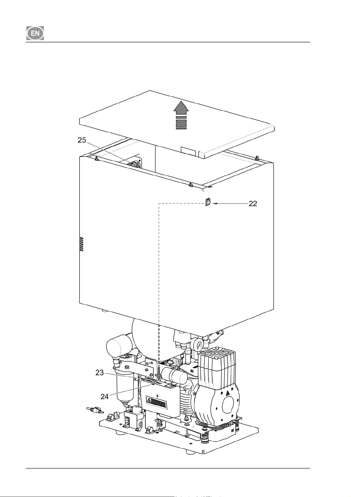
THE FOLLOWING IS REQUIRED BEFORE ANY FOLLOW-UP CHECKS:
For DK50-10S and DK50-10S/M compressors with an enclosure - remove / lift up the enclosure.
For the DK50-10S/M 10 bar compressor model with an enclosure - remove the cover of the
enclosure, disconnect the enclosure connector from the compressor connector and remove / lift up
the enclosure.
18.6. Safety valve check
(Fig. 14)
When the compressor is operated for the first time, make sure that
the safety valve is working properly. Turn the screw (2) on the
safety valve (1) several rotations to the left until the safety valve
releases air. Let the safety valve vent for only a few seconds. Turn
the screw (2) to the right until it seats, closing the valve.
Never use the safety valve to vent air pressure in
the air tank. It could damage the safety valve. The
valve is set to the maximum permitted pressure by
the manufacturer. Adjustments are not permitted!
Warning! Compressed air can be dangerous. Wear
eye protection when venting any air. Compressed
1
2
air may damage the eyes or cause vision
problems.
NP-DK50-1_08-2017-MD - 26 - 08/2017
Fi
.14
DK50-10
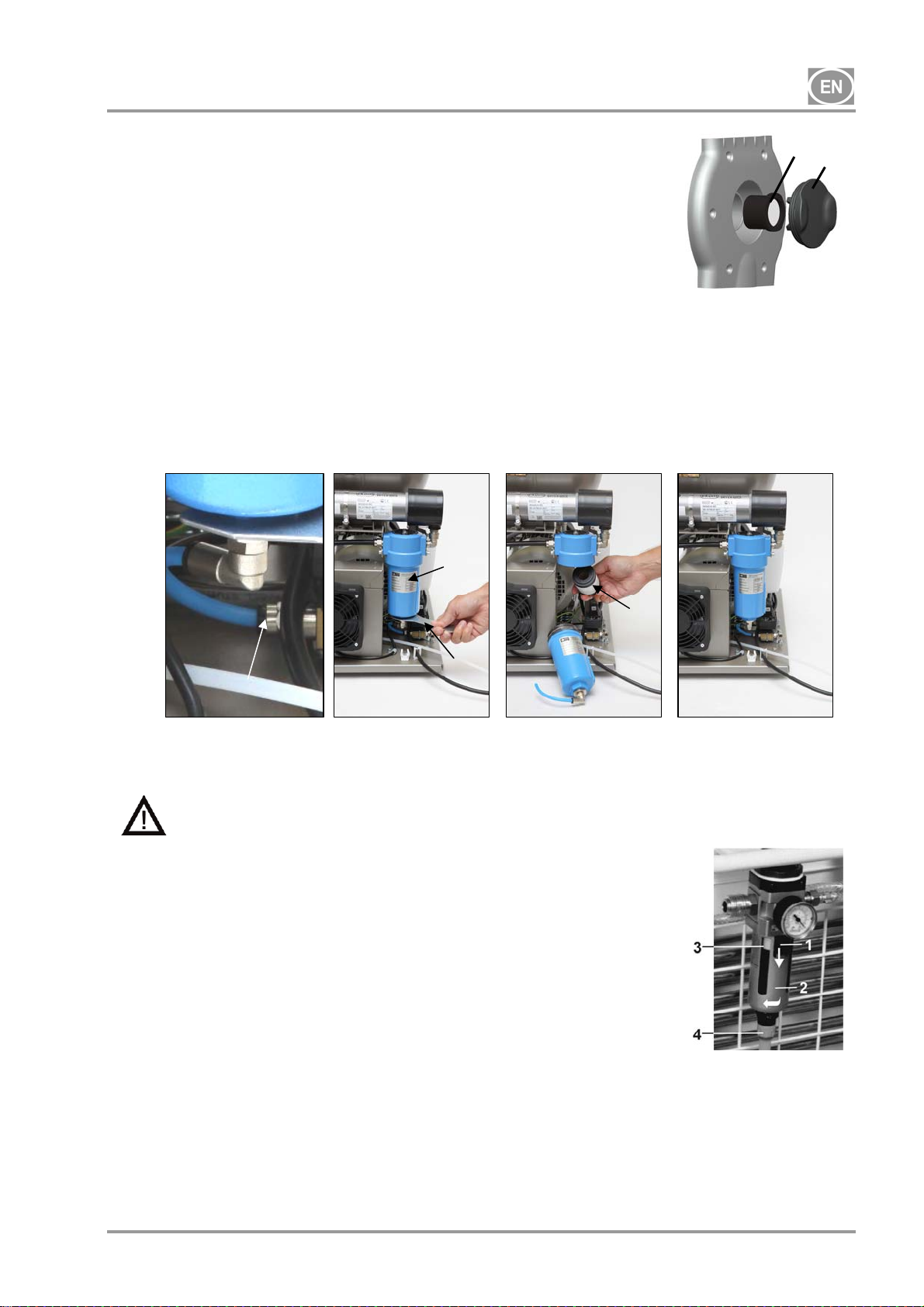
18.7. Inlet filter replacement
(Fig.15)
Pull out the rubber plug (2) by hand.
Remove the dirty inlet filter (1).
Insert a new filter and replace the rubber plug.
18.8. Filter element replacement
Fig.15
(Fig.16)
Remove the hose (1) from the quick connector.
Use a wrench (2) to release the filter vessel (3) and remove.
Pull down on the filter element (4) to remove.
Insert a new filter element.
Re-install the filter vessel.
Gently tighten the filter vessel with the wrench.
Install the hose back on the quick connector.
Fig.16
1
3
2
18.9. Filter element replacement in the KJF-1 unit
4
Before proceeding, vent the air tank to zero pressure and disconnect the equipment from
power.
(Fig.17)
Replace the filter inside the automatic condensate drain when
the condensate unit is in regular operation.
Release the catch (1) on the filter vessel by pulling
downward, rotate the filter cover (2) to the left and remove.
Unscrew the filter bracket (3) by turning it to the left.
Replace and secure the new filter by rotating the filter
bracket to the right back against the filter body.
Replace the filter cover and secure it by turning to the right
until the catch locks.
Fig.17
18.10. Cooler and fan check (Fig.3)
The equipment altogether, and especially the compressor fan, cooler fan (21) and cooler (14), must be kept
clean to ensure efficient drying performance; vacuum or blow down the cooling fins and fans with
compressed air to remove any dust from the surface.
08/2017 - 27 - NP-DK50-1_08-2017-MD
DK50-10
TROUBLESHOOTING
Caution! Before proceeding, depressurize the air tank to zero and disconnect the
appliance from the mains.
For permanently high efficiency of drying, it is necessary to maintain the whole appliance, and
mainly ventilator clean – regularly clean the surface of ventilator and cooling fins of cooler.
Troubleshooting can be performed only by qualified personnel.
MALFUNCTIONS POSSIBLE CAUSE REMEDY
Compressor does not
start
Compressor often
switches on
Low pressure in air
tank (compressor
running constantly)
Prolonged operation
of the compressor
Compressor is noisy
(knocking, metal
noises)
Dryer doesn't dry
(condensed water in
the air) *
No voltage at the pressure switch
Check voltage in socket
Check the circuit breaker – switch into the
“I” on position
Loose conductor at terminal – tighten
Check the electrical cord – replace
defective cord
Motor winding failure, damaged
thermal overload protection
Faulty capacitor
Seized piston or other rotating part
Pressure switch does not switch
Air leak in compressed air distribution
system
Leaking check valve
Large volume of condensed liquid in
pressure vessel
Replace motor or windings
Replace capacitor
Replace damaged parts
Check the function of the pressure switch
Check compressed air distribution
system – seal loose joints
Clean solenoid valve, replace seals,
replace solenoid valve
Drain condensed liquid
Check the time to fill the air tank
Low compressor performance
High air usage by appliance, Leak in
compressed air system, Low aggregate
output
Aggregate malfunction
Dryer malfunction
Air leak in compressed air distribution
system
Worn piston ring
Inlet filter is plugged
Defective solenoid valve
Damaged piston bearing, piston rod,
motor bearing
Loose or cracked spring
Check compressed air distribution
system – seal loose joint
Replace worn piston ring
Replace old filter with a new filter
Repair or change the valve or coil
Replace damaged bearing
Replace damaged spring
Cooling fan not working Replace the fan
Check the power source
Damaged dryer Replace the dryer
Non-functioning automatic condensate
Clean / replace
drain - clean / replace on the filter
)* After a dryer malfunction, the interior surfaces of the air tank must be thoroughly cleaned and all
condensed liquid removed.
Check the dew point of the air leaving the air tank (see Chapter 5 - Technical data) to protect the
equipment from damage!
NP-DK50-1_08-2017-MD - 28 - 08/2017
 Loading...