

EKOM DK50-10 Series, DK50-10 S/M, DK50-10 Z/K, DK50-10 S, DK50-10 Z User Manual [en, fr, de, ru]
...Page 1
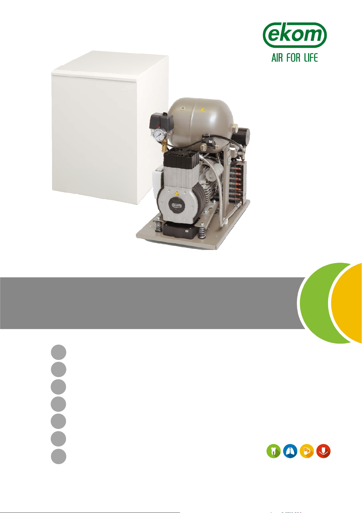
DK50-10
EN
User manual
DE
Benutzerhandbuch
FR
RU
Manuel de l’utilisateur
Руководство пользователя
PL
SK
Instrukcja obsługi
Návod na použitie
CS
Návod k použití
Page 2

Page 3

CONTENTS................................. 2
INHALT....................................... 30
SOMMAIRE................................ 58
СОДЕРЖАНИЕ.......................... 86
SPIS TREŚCI.............................. 114
OBSAH………............................. 142
OBSAH………............................. 170
Ed. - 1
08/2017 - 1 - NP-DK50-1_08-2017-MD
Page 4

DK50-10
CONTENTS
IMPORTANT INFORMATION ................................................................................................................. 3
1. CE MARKING ............................................................................................................................ 3
2. WARNINGS ................................................................................................................................ 3
3. WARNINGS AND SYMBOLS ..................................................................................................... 4
4. STORAGE AND TRANSPORT ................................................................................................... 5
5. TECHNICAL DATA ..................................................................................................................... 6
6. PRODUCT DESCRIPTION ......................................................................................................... 9
7. PRODUCT FUNCTIONALITY ................................................................................................... 11
8. PNEUMATIC SCHEMATIC ....................................................................................................... 15
OPERATION .......................................................................................................................................... 16
9. SWITCHING THE COMPRESS OR ON ................................................................................... 16
INSTALLATION ..................................................................................................................................... 17
10. CONDITIONS FOR USE .......................................................................................................... 17
11. PLACEMENT OF THE COMPRESSOR ................................................................................... 18
12.PNEUMATIC CONNECTIONS ................................................................................................. 19
13. ELECTRICAL CONNECTIONS ................................................................................................ 19
14. CONNECTION SCHEMATIC .................................................................................................... 20
15. COMMISSIONING .................................................................................................................... 22
16. SWITCHING THE COMPRESSOR ON .................................................................................... 22
17. COMPRESSOR SHUT-DOWN ................................................................................................. 22
MAINTENANCE .................................................................................................................................... 23
18.EQUIPMENT MAINTENANCE ................................................................................................. 23
TROUBLESHOOTING .......................................................................................................................... 28
19.REPAIR SERVICE .................................................................................................................... 29
20.STORAGE ................................................................................................................................. 29
21.DISPOSING OF THE APPLIANCE ........................................................................................... 29
ANNEX ................................................................................................................................................ 198
22.INSTALLATION RECORD ...................................................................................................... 198
NP-DK50-1_08-2017-MD - 2 - 08/2017
Page 5

DK50-10
IMPORTANT INFORMATION
1. CE MARKING
Products labeled with the CE mark of compliance meet the safety guidelines (93/42/EEC) of the European
Union.
2. WARNINGS
The product is designed and manufactured to be safe for the user and its surrounding environment when
used in the defined manner. Keep the following warnings in mind. This keeps risks to a minimum.
2.1. General warnings
The user manual aids in correct installation, operation and maintenance of the product. It is included with
the product and must be kept close to it at all times. Careful review of this manual will provide the
information necessary for correct operation of the product.
Original packaging should be kept for the return of the equipment. Only the original packaging ensures
protection of the equipment during transport. If it is necessary to return the product during the warranty
period, the manufacturer is not liable for damages caused by improper packaging.
This warranty does not cover damages originating from the use of accessories or consumables other
than those specified or suggested by the manufacturer.
The manufacturer only guarantees the safety, reliability and function of the equipment if:
- installation, new settings, changes, expansion and repairs are performed by the manufacturer or a
service provider authorized by the manufacturer.
- the product is used pursuant to the user manual.
The user manual corresponds to the configuration of the product and its compliance with applicable
safety and technical standards at the time of its printing. The manufacturer reserves all rights for the
protection of its configuration, methods and names.
Translation of the user manual is performed in accordance with the best available knowledge. The
Slovak version is to be used in the event of any uncertainties.
2.2. General safety warnings
The manufacturer designed and manufactured the product to mitigate all risks when used correctly. Please
note the following safety measures to mitigate residual risks.
Use and operation of the product must comply with all local codes and regulations. The operator and
user are responsible for following all appropriate regulations in the interests of performing work safely.
Only the use of original parts guarantees the safety of operating personnel and flawless operation of the
product itself. Only accessories and parts mentioned in the technical documentation or expressly
approved by the manufacturer may be used.
The operator must ensure the equipment is functioning correctly and safely before every use.
The user must fully understand the operation of the equipment.
Do not use the product in explosive environments.
The user must inform the supplier immediately if any problem occurs during use of the equipment.
08/2017 - 3 - NP-DK50-1_08-2017-MD
Page 6
DK50-10
2.3. Electrical system safety warnings
The equipment may only be connected to a properly installed socket connected to earth (grounded).
Before the product is plugged in, make sure that the mains voltage and frequency stated on the product
are the same as the power mains.
Check for any damage to the connected compressed air system and electrical circuit before use.
Replace damaged pneumatic and electrical conductors immediately.
Immediately disconnect the product from the mains (remove the power cord from the socket) in
hazardous situations or when a technical malfunction occurs.
Ensure the following during any maintenance and repairs:
- the mains plug is pulled out from the power socket
- pressure is vented from the compressed air lines and the air tank
Only a qualified technician may install the product.
3. WARNINGS AND SYMBOLS
The following labels and symbols are used in the user manual and on the equipment and its packaging to
indicate important details and information:
Information, instructions and cautions for the prevention of damage to health or
materials
Caution! Dangerous electric voltage
Read the user manual!
CE mark of compliance
Caution! Hot surface
Compressor is remote-controlled and may start without warning
Earth (ground) connection
Terminal for ground connection
Fuse
Alternating current
Handling mark on package – FRAGILE
Handling mark on package – THIS SIDE UP
NP-DK50-1_08-2017-MD - 4 - 08/2017
Handling mark on package – KEEP DRY
Handling mark on package – TEMPERATURE LIMITATIONS
Handling mark on package – LIMITED STACKING
Mark on package – RECYCLABLE MATERIAL
Page 7
DK50-10
4. STORAGE AND TRANSPORT
The compressor is shipped in cardboard that protects the appliance from damage during transport.
Caution! For transport, always use the original packaging and secure the compressor in
the upright position.
Protect the compressor from humidity and extreme temperatures during transport and storage. A
compressor in its original packaging can be stored in a warm, dry and dust-free area. Do not
Ambient conditions for storage and transport
Products may only be stored and transported in vehicles that are free of any traces of volatile chemicals
under the following conditions:
store near any chemical substances.
Keep packaging material if possible. If not, please dispose of the packaging material in an
environmentally friendly way and recycle if possible.
Caution! Before moving or transporting the compressor, release all the air pressure from
the tank and hoses and drain the condensed water.
Temperature: –25°C to +55°C, 24 h at up to +70°C
Relative humidity: 10% to 90% (non-condensing)
08/2017 - 5 - NP-DK50-1_08-2017-MD
Page 8
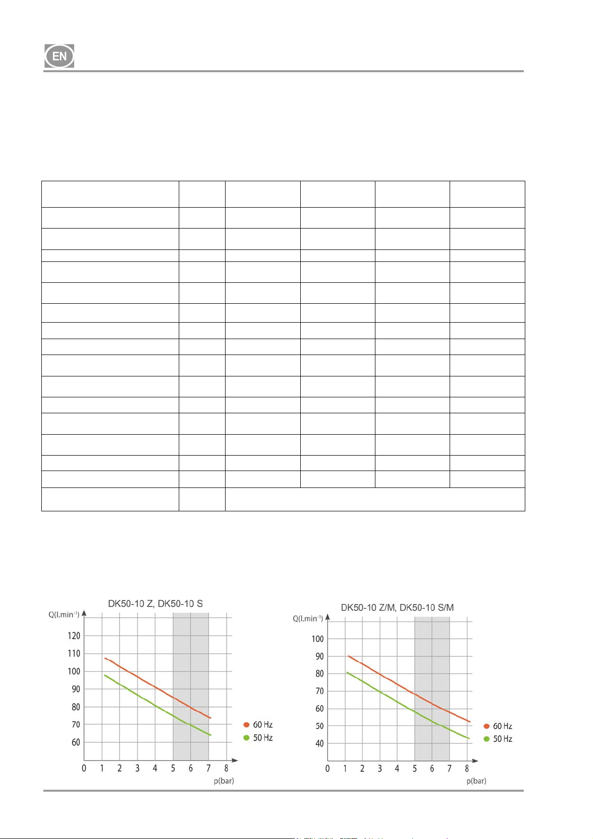
DK50-10
5. TECHNICAL DATA
Compressors are designed for dry and ventilated indoor environments with the following conditions:
Temperature : +5°C až +40°C,
Max. relative humidity.: 70%,
Max. absolute humidity. 15 g/m
Tab.1
3
5 – 7 bar
Nominal voltage / frequency (*) V / Hz
Output
at 5 bar
Working pressure (**) bar 5.0 – 7.0 5.0 – 7.0 5.0 – 7.0 5.0 – 7.0
Output with KJF-1
at 5 bar
Max. current A
Motor output kW 0.55 0.55 0.55 0.55
Air tank volume Lit. 10 10 10 10
Air quality – filtration
Maximum operating pressure of
safety valve
Noise level at 5 bar LpfA [dB]
Operating mode 100% - S 1 100% - S 1 100% - S 1 100% - S 1
PDP - drying performance at 7
bar
Time to fill air tank from 0 to 6
bar
Dimensions (net) w x d x h mm 485x350x553 580x440x655 544x350x553 649x440x655
Net weight kg 38 (***) 53 (***) 44
Configuration per
EN 60601-1
Lit.min-1
Lit.min-1
m
bar 8.0 8.0 8.0 8.0
- -
s
Type B, class I.
DK50-10 Z DK50-10 S DK50-10 Z/M
230 / 50/60
115 / 60
75 / 85
85
75 / 85
85
3.8 / 4.8
9.5
- - 0.3 0.3
65 / 66.5
66.5
50 / 44
44
230 / 50/60
115 / 60
75 / 85
85
75 / 85
85
3.8 / 4.8
9.5
49.5 / 51
51
50 / 44
44
230 / 50/60
115 / 60
58 / 68
68
- -
4.1 / 5.1
10
67 / 68.5
68.5
+3°C
70/60
60
DK50-10 S/M
230 / 50/60
115 / 60
58 / 68
68
4.1 / 5.1
10
51.5 / 53
53
+3°C
70/60
60
61
Notices:
(*) When ordering, state the version of compressor
(**) Range of pressure: consult with contractor
(***) Weight of compressors with a KJF1 unit _add 3 kg
(****) The permitted operating pressure of the safety valve can also be set to another value, e.g. 9 bar /
the setting shall be specified in the order.
NP-DK50-1_08-2017-MD - 6 - 08/2017
Page 9
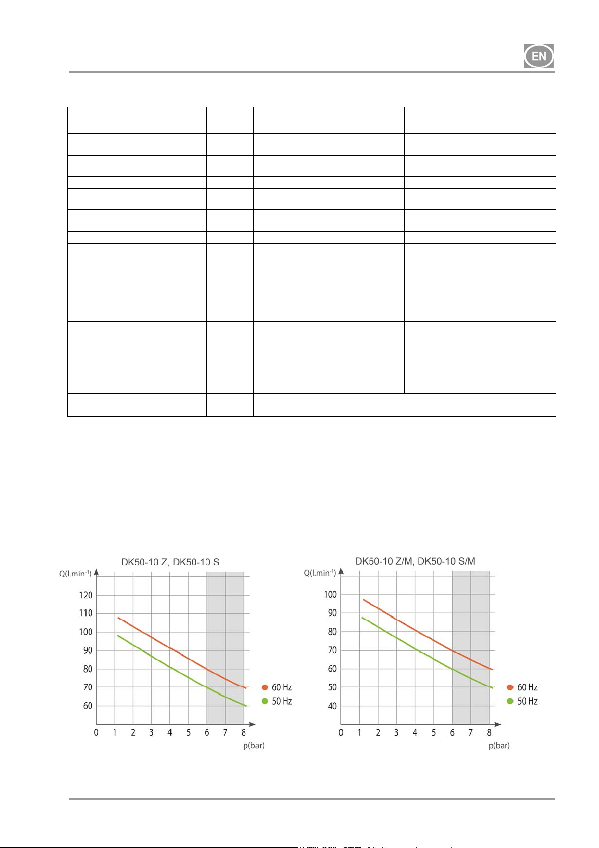
DK50-10
Tab. 2
6 – 8 bar
Nominal voltage / frequency (*) V / Hz
Output
at 6 bar
Working pressure (**) bar 6.0 – 8.0 6.0 – 8.0 6.0 – 8.0 6.0 – 8.0
Output with KJF-1
at 6 bar
Max. current A
Motor output kW 0.55 0.55 0.55 0.55
Air tank volume 10 10 10 10
Air quality – filtration
Maximum operating pressure of
safety valve
Noise level at 5 bar LpfA [dB]
Operating mode
PDP drying performance at 7
bar
Time to fill air tank from 0 to 7
bar
Dimensions (net) w x d x h mm 485x350x553 580x440x655 544x350x553 649x440x655
Net weight kg 38 (***) 53 (***) 44
Configuration per
EN 60601-1
Lit.min-1
Lit.min-1
m
bar 12.0 12.0 12.0 12.0
- -
s
DK50-10 Z DK50-10 S DK50-10 Z/M
230 / 50/60
115 / 60
70 / 80
80
70 / 80
80
3.9 / 4.9
9.8
- - 0.3 0.3
65 / 66.5
66.5
100% - S 1 100% - S 1 100% - S 1 100% - S 1
60 / 51
51
230 / 50/60
115 / 60
70 / 80
80
70 / 80
80
3.9 / 4.9
9.8
49.5 / 51
51
60/51
51
Type B, class I.
230 / 50/60
115 / 60
60 / 70
70
- -
4.1 / 5.1
10.2
67 / 68.5
68.5
+3°C
72/61
61
DK50-10 S/M
230 / 50/60
115 / 60
60 / 70
70
4.1 / 5.1
10.2
51.5 / 53
53
+3°C
72/61
61
61
Notices:
(*) When ordering, state the version of compressor
(**) Range of pressure: consult with contractor
(***) Weight of compressors with a KJF1 unit _add 3 kg
(****) The permitted operating pressure of the safety valve can also be set to another value, e.g. 9 bar /
the setting shall be specified in the order.
08/2017 - 7 - NP-DK50-1_08-2017-MD
Page 10

DK50-10
Tab. 3
8 – 10 bar
Nominal voltage / frequency (*) V / Hz
Output
at 8 bar
Working pressure (**) bar 8.0 – 10.0 8.0 – 10.0 8.0 – 10.0 8.0 – 10.0
Output with KJF-1
at 8 bar
Max. current A
Motor output kW 0.55 0.55 0.55 0.55
Air tank volume 10 10 10 10
Air quality – filtration
Maximum operating pressure of
safety valve
Noise level at 5 bar LpfA [dB]
Operating mode
PDP drying performance at 7
bar
Time to fill air tank from 0 to 9
bar
Dimensions (net) w x d x h mm 485x350x553 580x440x655 544x350x553 649x440x655
Net weight kg 38 (***) 53 (***) 44
Configuration per
EN 60601-1
Lit.min-1
Lit.min-1
m
bar 12.0 12.0 12.0 12.0
- -
s
DK50-10 Z DK50-10 S DK50-10 Z/M
230 / 50/60
115 / 60
60 / 70
70
60 / 70
70
4.1 / 5.1
10.2
- - 0.3 0.3
65 / 66.5
66.5
100% - S 1 100% - S 1 100% - S 1 100% - S 1
85/75
75
230 / 50/60
115 / 60
60 / 70
70
60 / 70
70
4.1 / 5.1
10.2
49.5 / 51
51
85/75
75
Type B, class I.
230 / 50/60
115 / 60
50 / 60
60
- -
4. / 5.3
10.5
67 / 68.5
68.5
+3°C
96/82
82
DK50-10 S/M
230 / 50/60
115 / 60
50 / 60
60
4.4 / 5.4
10.5
51.5 / 53
53
+3°C
96/82
82
61
Notices:
(*) When ordering, state the version of compressor
(**) Range of pressure: consult with contractor
(***) Weight of compressors with a KJF1 unit _add 3 kg
(****) The permitted operating pressure of the safety valve can also be set to another value, e.g. 9 bar /
the setting shall be specified in the order.
NP-DK50-1_08-2017-MD - 8 - 08/2017
Page 11
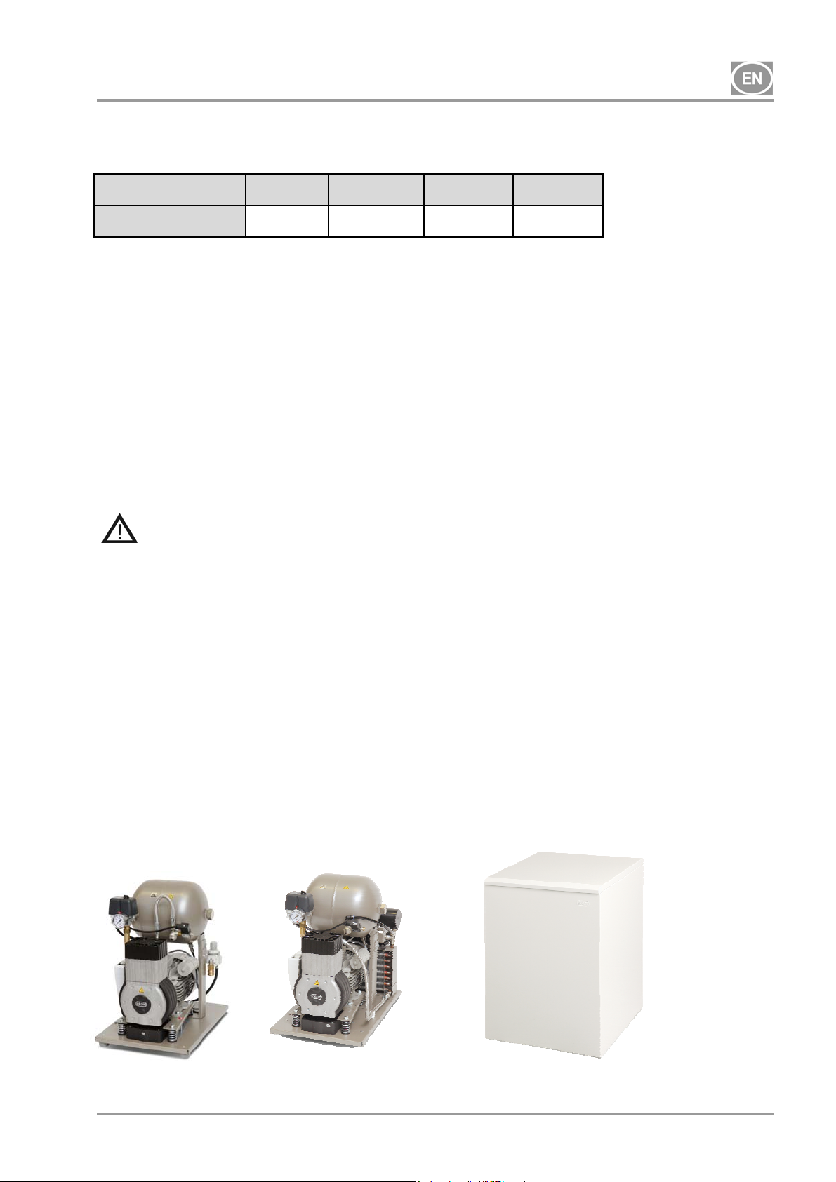
DK50-10
5.1. Free air delivery (FAD) correction due to elevation
FAD correction table
Elevation [mamsl] 0 - 1500 1501 - 2500 2501 - 3500 3501 - 4500
FAD [l/min] FAD x 1 FAD x 0.8 FAD x 0.71 FAD x 0.60
FAD output related to conditions:
Elevation: 0 MASL Temperature : 20°C
Atmospheric pressure : 101325 Pa Relative humidity : 0%
6. PRODUCT DESCRIPTION
6.1. Model variations and their uses
The compressor is used as a source of clean, oil-free compressed air to power dental equipment,
instruments and devices in laboratories where the parameters and properties of the compressed air are
suitable to the specific application.
Compressed air supplied by the compressor is unsuitable for use with artificial lung
ventilation devices without further filtration
Any use of the equipment outside the framework defined herein is considered inappropriate use. The
manufacturer is not liable for any damages or injury occurring as a result of inappropriate use.
6.2. Description
Compressor models are designed for the following uses:
DK50-10 Z compressor - a base-mounted compressor for stand-alone installation in a given space
DK50-10 Z/K compressor - a base-mounted compressor with a condensate and filtration unit (KJF1)
DK50-10 Z/M compressor - a base-mounted compressor with an air dryer
DK50-10 S compressor - an enclosed compressor with effective noise dampening for in-office installations
DK50-10 S/K compressor - an enclosed compressor with a condensate and filtration unit (KJF1)
DK50-10 S/M compressor - an enclosed compressor with an air dryer
DK50-10 Z
DK50-10 Z/M
DK50-10 S
DK50-10 S/M
08/2017 - 9 - NP-DK50-1_08-2017-MD
Page 12
DK50-10
6.3. Accessories
Accessories not included in the standard order must be ordered separately!
6.3.1 Automatic condensate drain
The automatic condensate drain (AOK) automatically drains condensate from the compressor’s air tank
based on a pre-set time interval. The condensate drain (AOK) is a suitable accessory for compressor
models without dryers.
6.3.2 Set of filters
Compressors may be equipped with a set of filters on the compressed air outlet if specified. The set of filters
may be equipped with a pressure regulator. Sets of filters are suitable accessories for all the compressors
specified above.
NOTE : If a higher level of air filtration is required, this specification must be agreed upon with the supplier
and made clear in the order.
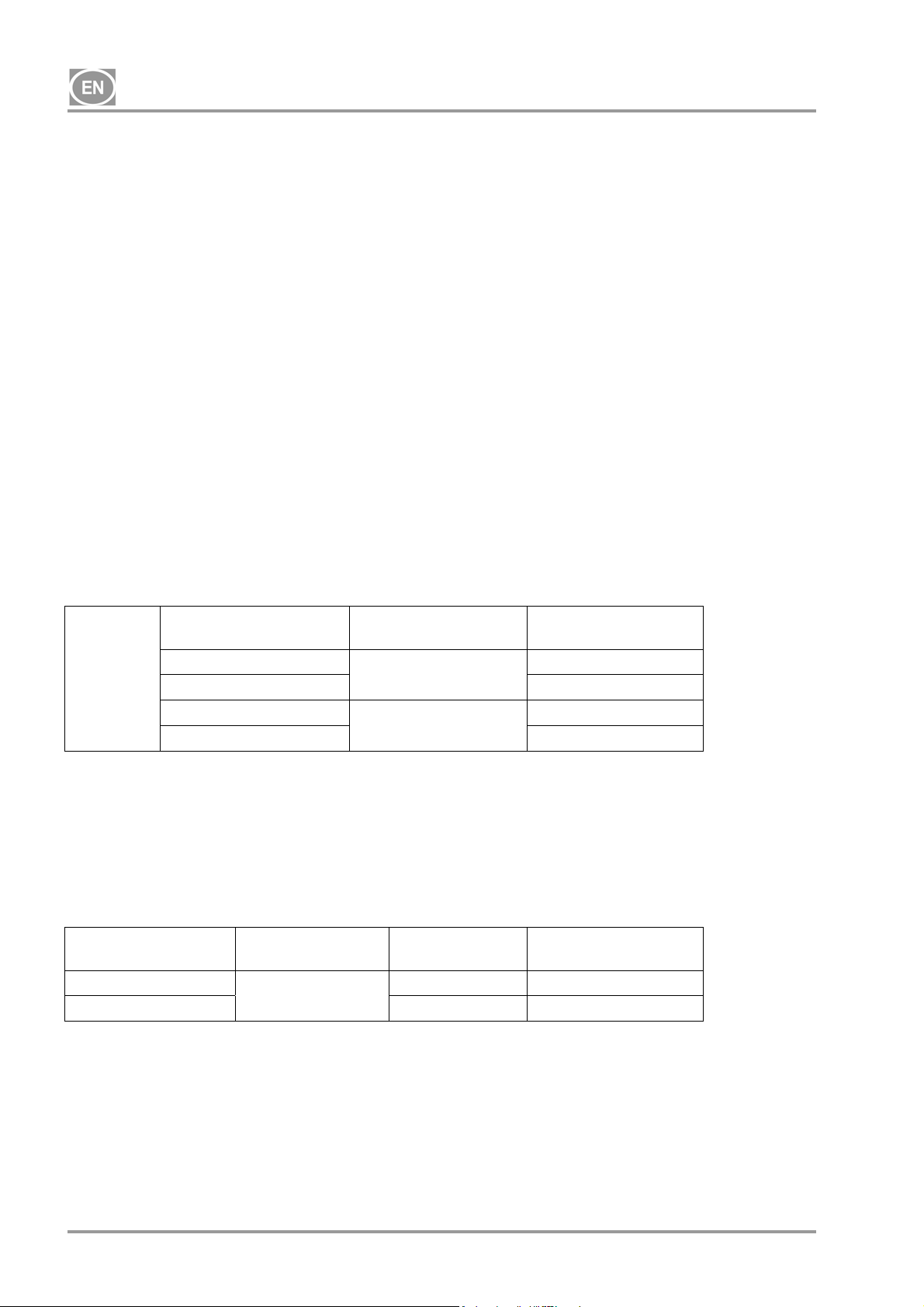
Level of filtration Pressure regulator Kit article no.
SET OF
FILTERS
6.3.3 Condensation and filtration unit (KJF)
The compressor may additionally be fitted with a condensation and filtration unit (KJF-1 or KJFR-1). The
KJF-1 or KJFR-1 ensure that the compressed air from the air tank is cooled in the cooler and the
condensate is captured in the filter and automatically separated from the compressed air circuit. The
compressed air is filtered at the same time.
Condensation and
filtration unit
KJF-1
KJFR-1 Yes 450001011-002
-
5µm 604013233-000
0,3µm
0,01µm 604013235-000
Level of filtration
5µm
Yes
No
Pressure
regulator
No 450001011-001
604013245-000
604013234-000
Kit article no.
NP-DK50-1_08-2017-MD - 10 - 08/2017
Page 13
DK50-10
7. PRODUCT FUNCTIONALITY
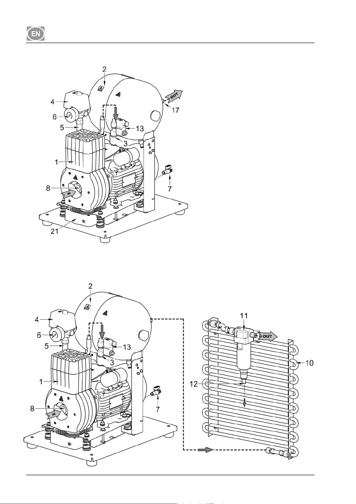
Compressor (Fig. 1)
The compressor aggregate (1) draws in air through an inlet filter (8) and compresses it through a check
valve (3) into an air tank (2) from which the appliance draws compressed air. If the pressure in the air tank
drops to the switching pressure, the pressure switch (4) turns on the compressor and the compressor
supplies compressed air to the air tank until it reaches the switch off pressure, at which time the compressor
switches off. The pressure hose is vented through the relief solenoid valve (13) once the compressor unit is
shut off. The safety valve (5) prevents the pressure in the air tank from rising above the maximum allowed
value. The drain valve (7) drains condensate from the air tank. Compressed, oil-free filtered air is stored in
the air tank ready for use.
Condensate must be drained from the air tank at regular intervals (see Chapter 18).
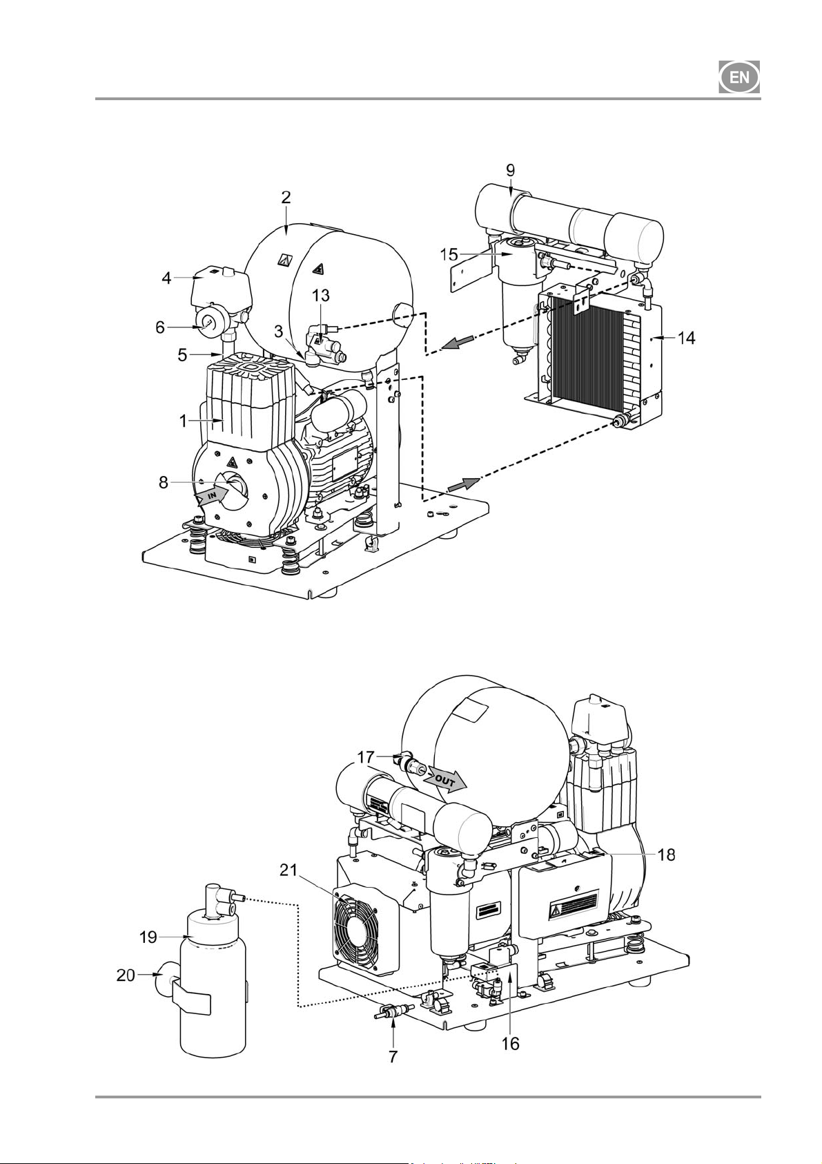
Compressor with membrane dryer. (Fig. 3)
The compressor aggregate (1) draws in air through an inlet filter (8) and compresses it, feeding it to the
cooler (14) through the filter (15) to the dryer (9) and the dry, clean air is then fed through the check valve
(3) into the air tank (2). A portion of the air bypasses the dryer with the captured moisture, which is
manifested as a gentle stream of air along the body of the dryer (9). Condensate from the filter is
automatically drained at regular intervals into the vessel via the condensate drain solenoid valve (16). The
dryer ensures continuous drying of the compressed air. The drain valve (7) drains condensate from the air
tank when drying performance is checked. Compressed, oil-free filtered air is stored in the air tank ready for
use.
The compressor with dryer requires no operator. The pressure vessel does not need to be drained.
Compressor with condensate and filtration unit (Fig. 2)
The compressor aggregate (1) draws in air through an inlet filter (8) and compresses it through a check
valve (3) into an air tank (2). Compressed air from the air tank flows through a cooler (10) that cools the
compressed air. The condensed moisture is trapped in the filter (11) and automatically separates as
condensate (12) into the vessel. Compressed, oil-free filtered air is ready for use.
Condensate must be drained from the air tank at regular intervals (see Chapter 18).
Compressor enclosure
The soundproof enclosure is compact and allows sufficient cooling air exchange. The design makes it
suitable for in-office installations in a way that blends in with other furniture. The fan under the compressor
aggregate ensures sufficient cooling for the compressor and runs with the compressor motor or when the
temperature switch is activated at temperatures above 40 °C.
Make sure that nothing impedes the free flow of air under and around the compressor.
Never cover the hot air outlet on the top back side of the case.
If placing the compressor on a soft floor such as carpet, create space for ventilation
between the base and floor or the box and floor, e.g. underpin the footings with hard
pads.
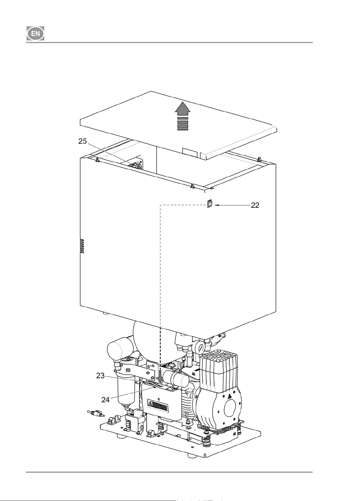
The 10 bar compressor model is equipped with an hour meter (Fig. 4).
08/2017 - 11 - NP-DK50-1_08-2017-MD
Page 14
DK50-10
Fig. 1 - DK50-10 Z - Compressor
Description for Figures 1-4
1. Compressor aggregate
2. Air tank
3. Check valve
4. Pressure switch
5. Safety valve
6. Pressure gauge
7. Drain valve
8. Inlet filter
9. Dryer
10. Pipe cooler
11. Filter
12. Condensate outlet
13. Solenoid valve
14. Dryer cooler
15. Filter
16. Valve with timer
17. Compressed air outlet
18. Breaker switch
19. Vessel
20. Magnetic bracket
21. Fan
22. Switch
23. Hour Meter
24. Connector
25. Box fan
Fig. 2 – DK50-10 Z/K - Compressor with KJF1 condensate and filtration unit
NP-DK50-1_08-2017-MD - 12 - 08/2017
Page 15
DK50-10
Fig. 3 - DK50-10 Z/M - Compressor with dryer
08/2017 - 13 - NP-DK50-1_08-2017-MD
Page 16
DK50-10
Fig. 4 - Compressor DK50-10 S/M - 10bar
NP-DK50-1_08-2017-MD - 14 - 08/2017
Page 17
DK50-10
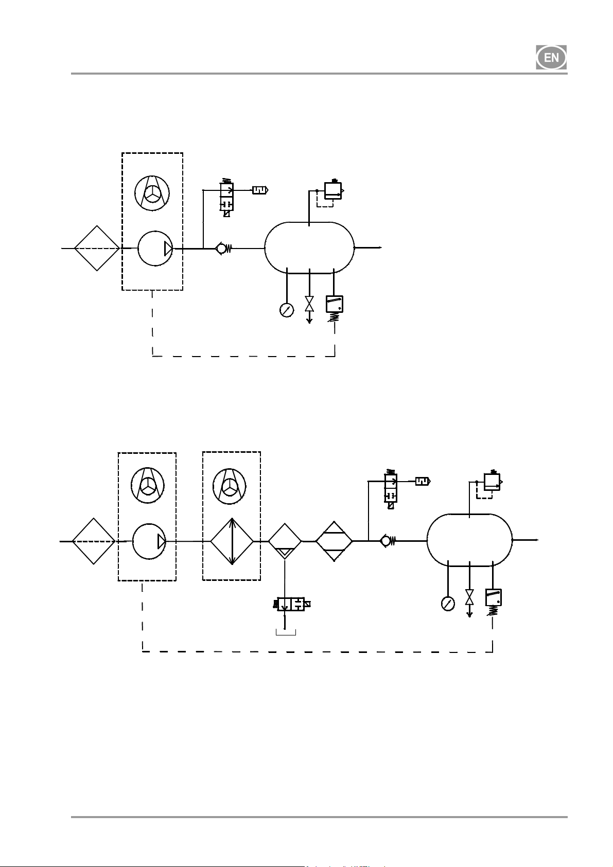
8. PNEUMATIC SCHEMATIC
DK50-10Z, DK50-10S
1
DK50-10Z/M, DK50-10S/M
1
Legend for compressed air schematics
1. Inlet filter
2. Compressor
3. Fan
4. Relief valve
5. Noise muffler
6. Check valve
7. Pressure gauge
8. Pressure switch
3
4
2
3
2
6
3
12
14
9
8
4
6
5
10
11
7
9
8
5
10
11
7
13
16
15
9. Safety valve
10. Air tank
11. Drain valve
12. Cooler
13. Coalescence filter
14. Membrane dryer
15. Condensate tank
16. Condensate drain solenoid valve
08/2017 - 15 - NP-DK50-1_08-2017-MD
Page 18
DK50-10
OPERATION
In case of emergency, disconnect the compressor from the mains (pull out the mains
plug).
The compressor has hot surfaces.
Burns or fire may result if contact is made.
During prolonged operation of the compressor, the temperature in the box may increase
The working pressure settings for the pressure switch set by the manufacturer cannot be changed.
Compressor operation at a working pressure below the switching pressure indicates high air usage by the
attached appliance (see the Malfunctions chapter)
9. SWITCHING THE COMPRESSOR ON
to over 40°C. At this point the cooling fan automatically switches on. After cooling the
space to under 32°C, the ventilator switches off.
Automatic start: when pressure in the tank drops to the pressure switch’s lower limit
level, the compressor automatically switches on. The compressor automatically switches
off after reaching the pressure switch’s upper limit level.
Required drying performance can only be achieved when following the defined operating
conditions!
Drying performance will decline and the achieved dew point will drop if the dryer is
operated at any pressure below the minimum working pressure!
The dryer will suffer damage if operated at ambient temperatures above the maximum
working temperature!
(Fig. 5)
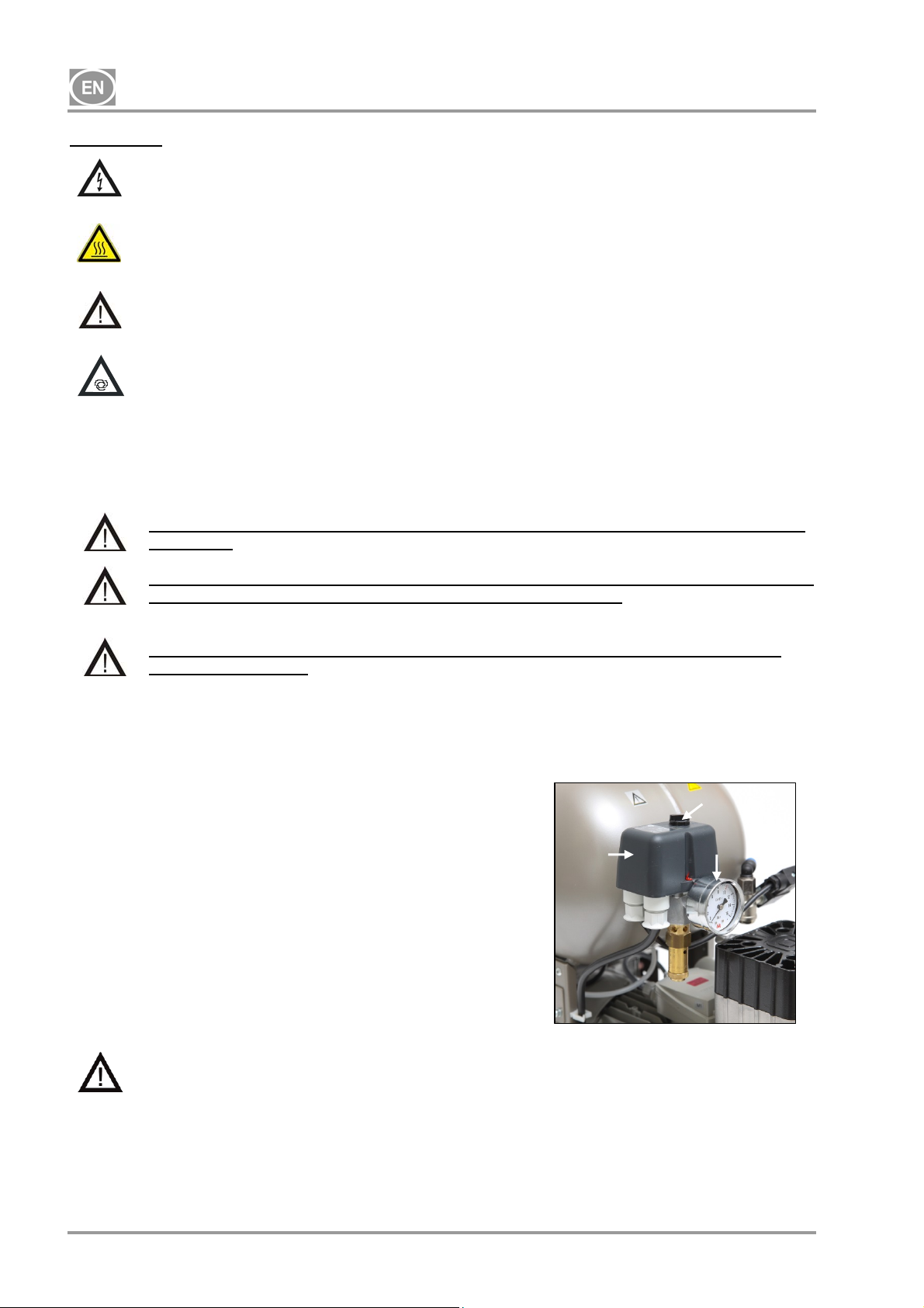
Turn the compressor on at the pressure switch (2) by rotating the
main switch (3) to the “I” position. Check the position of the breaker
switch, it must be in the “I” position. If it is in the “0” position, turn
the switch to the “I” position (Fig.3 – position 18). The switch (Fig. 4
– position 22) in the case of DK50-10 S/M 10bar compressors is on
the front side of the enclosure; the indicator lights up green. The
compressor switches on and begins to fill the air tank until the
pressure reaches the switching pressure and the pressure switch
turns the compressor off. The compressor then operates in
automatic mode and is controlled by the on and off pressure
settings on the pressure switch based on compressed air usage.
This pressure may be monitored on the pressure gauge (5). A
tolerance of 10% is acceptable. The pressure in the air tank may
not exceed the permitted operating pressure.
Changing the switching pressures on the pressure
switch is prohibited on any compressor.
The pressure switch (2) has been set by the manufacturer and further setting of switching on and off
pressure may be carried out only by a qualified expert trained by the manufacturer.
2
Fig. 8
Fig.5
3
5
NP-DK50-1_08-2017-MD - 16 - 08/2017
Page 19

DK50-10
INSTALLATION
10. CONDITIONS FOR USE
Compressors may only be installed and operating in dry, well-ventilated and clean environments with
environmental parameters that meet the requirements specified in Chapter 5, Technical data. The
compressor must be installed so that it is accessible at all times for operating and maintenance. Please
ensure that the nameplate on the device is readily accessible.
The compressor must stand on a flat, sufficiently stable base (be aware of the weight of the compressor,
see Chapter 5, Technical data).
Compressors may not be operated outdoors or in otherwise wet or damp environments. Do not use the
compressor in the presence of explosive gases, dust or flammable liquids.
Before connecting the compressor to medical equipment, the supplier must confirm that it meets all
requirements for its use. Refer to the technical data of the product for this purpose. When a unit is to be
built-in, classification and evaluation of compatibility must be done by the manufacturer or supplier of the
product to be used.
Any use other than that described in this manual is not covered by the guarantee, and the manufacturer is
not liable for any damages that may result. The operator/user assumes all risk.
Only a qualified professional may install the compressor and place it into operation for
the first time. This professional is obliged to train operating staff as to the use and
maintenance of the equipment. Installation and training of all operators shall be confirmed
by the installer’s signature on the certificate of installation.
Prior to installation, ensure that the compressor is free of all transport packaging and
stabilizers to avoid any risk of damage to the product.
Caution! When in operation, the compressor is hot. Burns or fire may result if contact is
made by the operator or any flammable material.
Ambient operating conditions
Temperature: +5°C to +40°C,
Max. relative humidity: 70%,
Max. absolute humidity: 15 g/m
3
.
08/2017 - 17 - NP-DK50-1_08-2017-MD
Page 20
DK50-10
11. PLACEMENT OF THE COMPRESSOR
The equipment shall only be installed by a qualified professional.
Unwrap the compressor from the packaging.
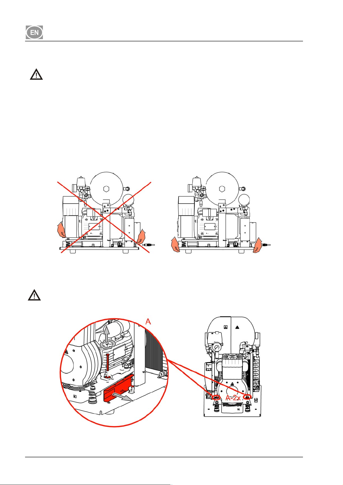
11.1. Handling and releasing the compressor
Position the compressor at the site of future operation (Fig. 6)
Fig.6
Remove the transport stabilisers from the aggregates. (Fig. 7)
Remove all devices used to secure the compressors once the compressor set has been installed
and mounted at the site of final installation!
Fig.7
NP-DK50-1_08-2017-MD - 18 - 08/2017
Page 21
DK50-10
12. PNEUMATIC CONNECTIONS
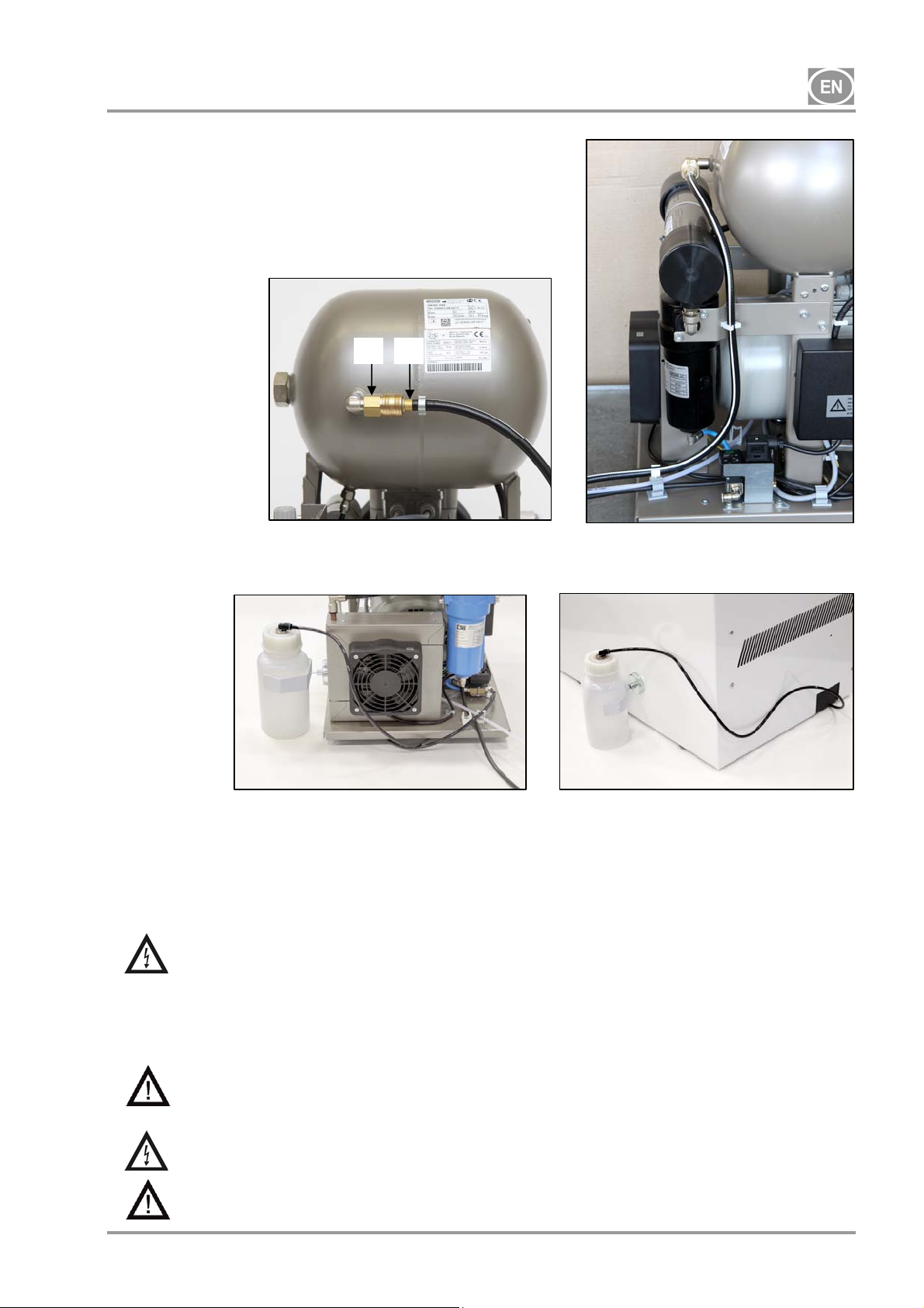
12.1. Compressed air outlet (Fig. 8)
Connect a pressure hose terminated at one end with a sliding
quick connector (1) to the compressed air outlet (2) on the
compressor and connect the hose to the compressed air
system or directly to the appliance, in this case dental
equipment.
Fig.8
12.2. Condensate outlet (Fig. 9)
2 1
Connect the condensate drain hose to the condensate vessel on compressors with dryers.
Fig. 9
Route the hose through the opening in the rear wall of the enclosure for other compressors (without
dryers).
13. ELECTRICAL CONNECTIONS
The product is equipped with a grounded plug. Insert the mains plug into a rated mains socket.
Ensure full compliance with all local electrical codes. The mains voltage and frequency
must comply with the data stated on the device's label.
Keep the socket easily accessible to ensure that in an emergency the appliance can be safely
disconnected from the mains.
Connection to the power distribution box must be max.16 A.
The enclosure for the DK50-10S/M 10 bar model compressor is equipped with a cooling fan
and a switch. The enclosure must be connected using the provided cord with connector to the
matching connector on the compressor’s electrical panel. (Fig. 4)
Ensure the electrical cable does not touch hot compressor components. Risk of electric
shock!
If any electrical cord or air hose is damaged it must be replaced immediately.
08/2017 - 19 - NP-DK50-1_08-2017-MD
Page 22

DK50-10
14. CONNECTION SCHEMATIC
DK50-10 Z, DK50-10 S - 5-7bar, 6-8, 8-10 bar
1/N/PE ~ 115V / 60 Hz
~ 230V / 50/60 Hz
00000
bk bu
P1*
bk
B2
5G1
bn gy
40°C
bk
3G1
1
bk-1bk-2
M
C1
M1
DK50-10 Z/M, DK50-10 S/M 5-7bar, 6-8 bar
1/N/PE ~ 115V / 60 Hz
~ 230V / 50/60 Hz
5G1
bn gy
bk
B2
40°C
bk
3G1
M
1
M1
bk-1bk-2
3G0,75
C1
X1
X1
bk
1
bk
bn
B1
p >
bu
2
U
B1
p >
bu
2
1
T
U
bu bu
bn
3G0,5
M4
N
3G0,75
3G0,75
N
bu
N
E2
bn
M3
* - only for 8-10bar version
bu bk
bu
P1
P2
F1
gnye
4
8
bu bu
bn
3G0,5
bn
bu
E1
3G1,5
CE
gnye
PE
bn
UN
gnye
bu bn
3G1,5
UK
PE
UN
M3
bu bk
F1
3G1,5
bu
bu
CE
P2
8
gnye
PE
P1
4
gnye
bn
UN
bu bn
3G1,5
PE
UN
UK
N
gnye
bu
bn
3G0,5
E1
NP-DK50-1_08-2017-MD - 20 - 08/2017
Page 23
DK50-10
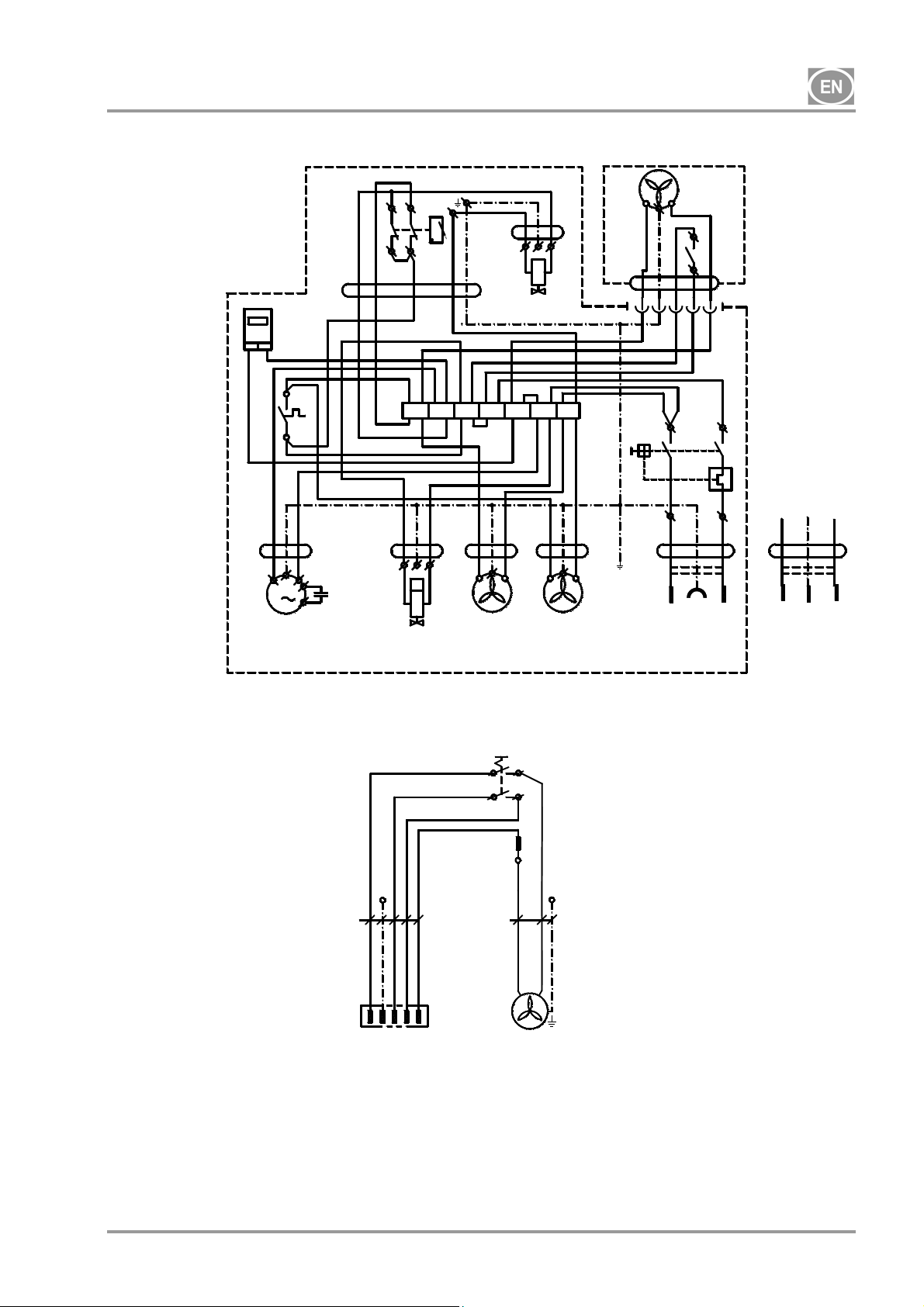
DK50-10 Z/M, DK50-10 S/M - 8-10 bar
1/N/PE ~ 230V 50..60Hz
Box for DK50-10 S/M - 10bar
Legend for electrical schematics
~ 115V 60Hz
bn gy
5G1
00000
P1
bkbu
bk
3G1
B2
40°C
bk
bk-1bk-2
M
1
X1
bn
3G0,75
C1
M1
* - only for DK50-10 Z/M version
1/N/PE ~ 230V 50..60Hz
bn
bu
PE
5G1
-X10
1
N23PE
M1 Compressor motor
E1 Compressor fan
E2 Dryer fan
M3 Solenoid valve
B2 Temperature switch
E3,E10 Box fan
X10, X2 Connector
B1
p >
3G0,75
bk
bu
2
1
U
U
bn
bu
M3
N
N
N
*
gnye
bu bu bu
T
bk
gy
M4
3G0,5
-S10
bn
E2
2
2a
1
1a
1
bn
3G0.5
3G0,5
bu
bu
bn
E1
PE
-E10
C1 Capacitor
B1 Pressure switch
X1 Terminal strip
F1 Protected switch
M4 Condensate drain valve
P1 Hour meter
S1 Switch
2
E3
S1
gy
5G1
bu
N
bu
F1
bu bk
3G1,5
bk
bn
1
32
bk
bk
bk
X2
bu
P1
P2
4
8
gnye
PE
bn
UN
bu bn
3G1,5
CE UK
1
1 - Compessor
2 - Box
gnye
PE
UN
08/2017 - 21 - NP-DK50-1_08-2017-MD
Page 24
DK50-10
15. COMMISSIONING
(Fig. 10)
Make sure all transport stabilizers were removed.
Check that all pressurized air line connections are secure.
Check to ensure power is connected correctly to the compressor.
Check the position of the main switch; it should be in the “I” position; if the switch remains in the “0”
position, turn the main switch to the “I” position. (Fig. 3)
Check to see if the DK50-10S/M enclosure (8-10 bar models only) is connected to the compressor using
the cable with the connector.
The compressor is not equipped with a backup power supply.
16. SWITCHING THE COMPRESSOR ON
(Fig. 10)
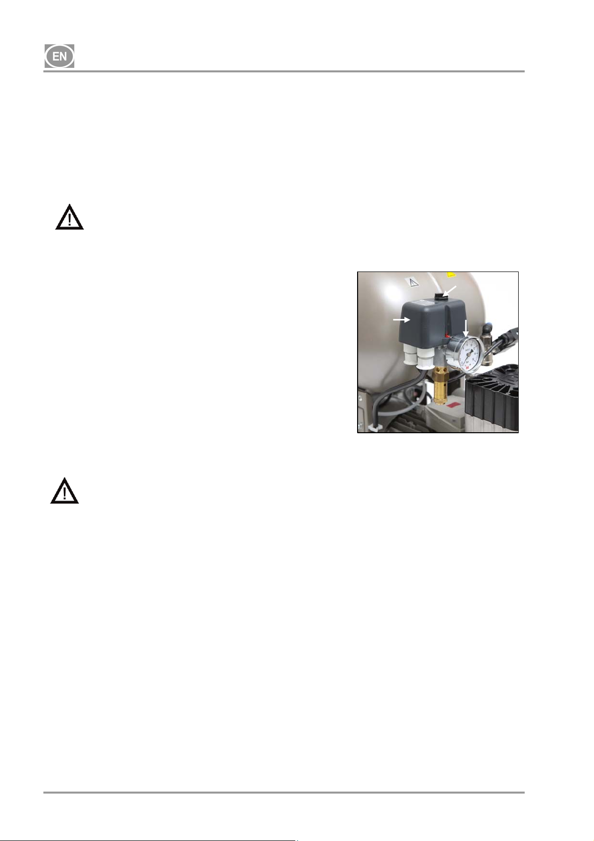
3
Turn the compressor on using the pressure switch (2) by rotating
the selector (3) to the “I” position. Check the position of the
breaker switch, it must be in the “I” position. If it is in the “0”
position, turn the switch to the “I” position (Fig.3 – position 18).
2
5
The switch (Fig. 4 – position 22) in the case of DK50-10S/M 10bar
compressors is on the front side of the enclosure; the indicator
lights up green. The compressor switches on and begins to fill the
air tank until the pressure reaches the switching pressure and the
pressure switch turns the compressor off. The compressor then
operates in automatic mode and is controlled by the on and off
pressure settings on the pressure switch based on compressed air
usage. This pressure may be monitored on the pressure gauge
(5). A tolerance of 10% is acceptable. The pressure in the air
tank may not exceed the permitted operating pressure.
Fig. 10
Adjustments to the pressure range on the compressor’s pressure switch are prohibited.
The pressure switch (2) was set up by the manufacturer and only a qualified technician
trained by the manufacturer may make any changes to its settings.
Compressor – when first started and placed into service, the compressor fills the air tank until the switching
pressure and the pressure switch turn off the compressor. The compressor operates in automatic mode,
switched on and off by the pressure switch, depending on compressed air usage.
Compressor with dryer – the compressor operates in the same manner as above, only the compressed air
passes through a cooler to remove moisture from the compressed air.
Compressor with a condensate and filtration unit (KJF-1) - during usage by the appliance, the
compressed air passes through the KJF-1 unit, where the air is cooled, filtered and condensed liquid is
captured and automatically drained into a vessel.
17. COMPRESSOR SHUT-DOWN
Compressor shut-down for service or any other reason is performed at the pressure switch (2) by turning the
selector (3) to the “0” position and pulling the mains plug from the socket. This disconnects the
compressor from power. Then open the drain valve (Fig. 1) to vent the pressure in the air tank to zero.
NP-DK50-1_08-2017-MD - 22 - 08/2017
Page 25
DK50-10
MAINTENANCE
18. EQUIPMENT MAINTENANCE
Warning!
The operator shall ensure completion of repeated testing of the equipment at least once every 24
months (EN 62353) or at intervals defined by applicable national legal regulations. A record of these
test results shall be completed (e.g. per EN 62353, Annex G) together with the measurement
methods.
The equipment has been designed and manufactured to keep maintenance to a minimum. The following
work must be performed to preserve the proper and reliable operation of the compressor.
Before starting compressor maintenance work, check to ensure the compressor is
disconnected from the appliance to ensure the person using the appliance is not at risk
and there is no risk of any other material damages!
Aggregate components (head, cylinder, pressure hose, etc.) are very hot during and
shortly after compressor operation – do not touch these components!
Repair work beyond normal maintenance can be performed only by qualified personnel or
he manufacturer’s representative.
Use only spareparts and accessories approved by the manufacturer.
Wear eye protection, i.e. goggles, when venting compressed air from the compressed air
circuit (air tank).
The work below may only be performed by trained personnel as follows:
BEFORE STARTING ANY MAINTENANCE WORK, IT IS NECESSARY to switch the
compressor off, disconnect it from the mains (pull out the mains plug) and vent the
compressed air from the air tank.
The 10 bar compressor model is equipped with an hour meter (Fig. 4), used to check the total hours of
operation.
08/2017 - 23 - NP-DK50-1_08-2017-MD
Page 26
DK50-10
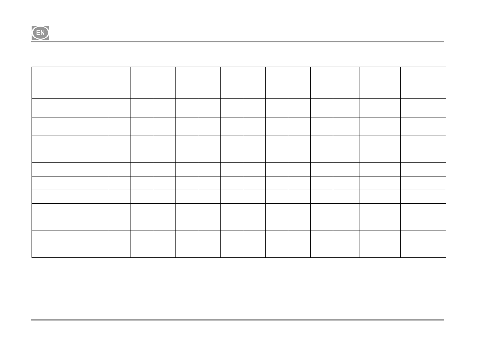
18.1. Maintenance intervals
Time interval
once
a day
once
a week
once
a year
once
every 2
years
2000 4000 6000 8000 10000 12000 Chapter
Set of spare
parts
Performed by
Produkto operational checks
Drain condensate from the air
tank )**
- At high humidity
Drain condensate from the air
tank )**
- At normal humidity
Product function check x
Leak check connections and
inspect equipment
Inspection of electrical
connections
Cooler and fan check
Filter element replacement
in the dryer filter
Filter element replacement in
theKJF-1
Safety valve check x
Conduct a “repeated test” per
EN 62353
Aggregate inlet filter
replacement )*
x 18.2 -
x
x
x
x
x
x
x
x 18 -
x x
)* data is presented in hours; if not possible, then the data is considered in years
)** only for compressors without dryers
18.5 - user
18.5 - user
7 - user
18.3 -
18.4 -
18.10 -
18.8 025200304-000
18.9 025200061-000
18.6 -
x x 18.7 025200126-000
user
qualified
professional
qualified
professional
qualified
professional
qualified
professional
qualified
professional
qualified
professional
qualified
professional
qualified
professional
NP-DK50-1_08-2017-MD - 24 - 08/2017
Page 27

DK50-10
18.2. Operational checks
Check aggregate condition – the aggregates should be operating normally without excessive vibration
or noise. Troubleshoot any problem or call in service personnel if trouble is detected
Visually inspect fan operation – the fans must be operating when the aggregates are running.
Troubleshoot any problem or call in service personnel if trouble is detected
Check to ensure the power cable and pneumatic hoses are undamaged. Replace damaged
components or call in service personnel.
Check the ambient temperature – the ambient temperature must be below the temperature limit (40
°C). Cool the space if the temperature is high.
On the compressor with dryer – open the plug on the condensate vessel to drain the condensate
18.3. Leak check compressed air connections and inspect the equipment
Leak check:
Leak check the compressed air lines when the compressor is running and under pressure (not during
regeneration venting).
A Use a leak analyser or soapy water to check all joints and connections for leaks. Tighten or reseal
the connection where leaks are found.
Equipment inspection:
Check the condition of the compressor aggregate for normal operation and noise levels.
Fan operation check - the fans must be running during the defined compressor work cycles
Check of temperature switch operation (B2) – heat the temperature switch to a temperature above
40°C (e.g. using a heat gun, being careful not to warp any plastic pieces nearby). Fan EV1 (and EV2
for a compressor with dryer) will start up once the temperature reaches 40°C so long as power is
connected to the compressor.
Check filter condition – the filters must be undamaged and sufficiently clean.
Check the condition of the aggregate itself and ensure there is no contamination inside the crankcase
or play in the crankshaft
Replace any defective parts as needed.
18.4. Inspection of electrical connections
Check all electrical connections on the equipment with the mains disconnected!
Inspection
Check the mechanical function of the main switch.
Check to ensure the power cable and connected wires are undamaged.
Visually inspect the connection of individual cables to the terminal strip.
Inspect all screw terminals for the protective green and yellow PE grounding conductor.
08/2017 - 25 - NP-DK50-1_08-2017-MD
Page 28
g
DK50-10
18.5. Condensation drain valve
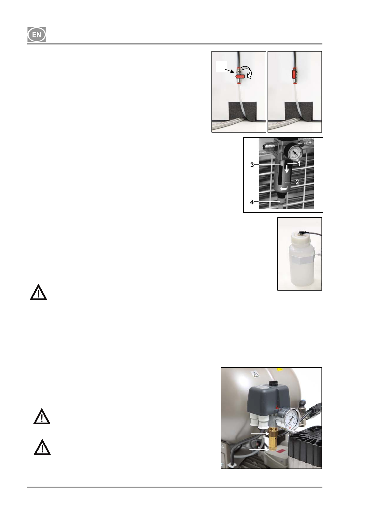
Compressors (Fig. 11)
1
Draining the condensate from the pressure vessel is
recommended during regular operation. Switch off the
compressor at the mains and lower the pressure to a maximum
of 1 bar, for instance, by venting air through the connected
equipment. Place the hose with the drain valve into a vessel
prepared in advance and open the drain valve (1) to remove the
condensate from the tank.
Fig.11
Compressors with condensation and filtration unit (Fig.12)
During regular use, condensation is automatically released via
the release valve of the condensation unit filter. To check that
the automatic drain is working properly, open the valve (4) of the
drain vessel (2) by turning to the left. Release a small amount of
condensate from the vessel. Close the valve (4) by turning to
the right.
Both types of compressors may be equipped with an automatic
Fig.12
condensate drain on the air tank condensate drain to allow the
condensate to drain without operator intervention (see the
Scope of Delivery – Accessories chapter).
Compressors with air dryer (Fig.13)
Condensate from compressors with air dryers is automatically
drained into a vessel. The vessel must be drained regularly, see
Chapter 18.2
Fig.13
THE FOLLOWING IS REQUIRED BEFORE ANY FOLLOW-UP CHECKS:
For DK50-10S and DK50-10S/M compressors with an enclosure - remove / lift up the enclosure.
For the DK50-10S/M 10 bar compressor model with an enclosure - remove the cover of the
enclosure, disconnect the enclosure connector from the compressor connector and remove / lift up
the enclosure.
18.6. Safety valve check
(Fig. 14)
When the compressor is operated for the first time, make sure that
the safety valve is working properly. Turn the screw (2) on the
safety valve (1) several rotations to the left until the safety valve
releases air. Let the safety valve vent for only a few seconds. Turn
the screw (2) to the right until it seats, closing the valve.
Never use the safety valve to vent air pressure in
the air tank. It could damage the safety valve. The
valve is set to the maximum permitted pressure by
the manufacturer. Adjustments are not permitted!
Warning! Compressed air can be dangerous. Wear
eye protection when venting any air. Compressed
1
2
air may damage the eyes or cause vision
problems.
NP-DK50-1_08-2017-MD - 26 - 08/2017
Fi
.14
Page 29
DK50-10
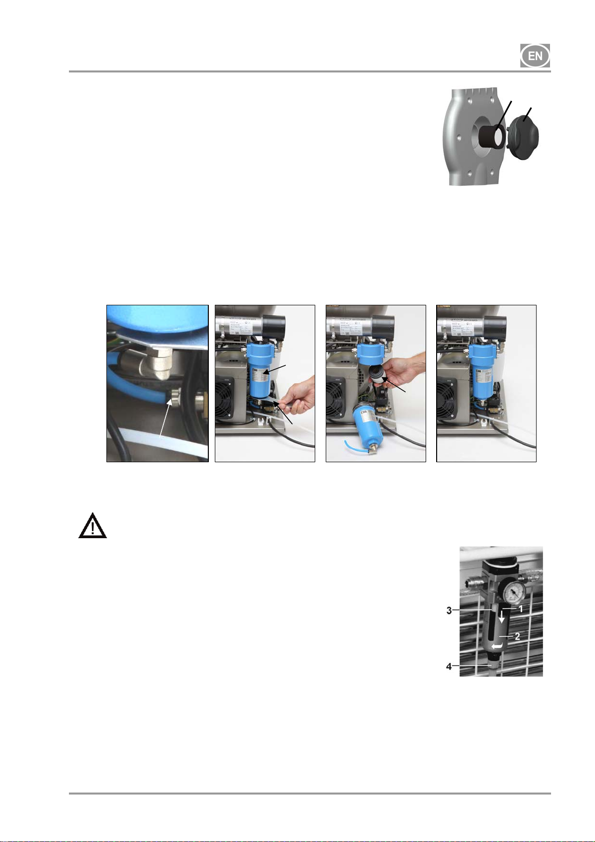
18.7. Inlet filter replacement
(Fig.15)
Pull out the rubber plug (2) by hand.
Remove the dirty inlet filter (1).
Insert a new filter and replace the rubber plug.
18.8. Filter element replacement
Fig.15
(Fig.16)
Remove the hose (1) from the quick connector.
Use a wrench (2) to release the filter vessel (3) and remove.
Pull down on the filter element (4) to remove.
Insert a new filter element.
Re-install the filter vessel.
Gently tighten the filter vessel with the wrench.
Install the hose back on the quick connector.
Fig.16
1
3
2
18.9. Filter element replacement in the KJF-1 unit
4
Before proceeding, vent the air tank to zero pressure and disconnect the equipment from
power.
(Fig.17)
Replace the filter inside the automatic condensate drain when
the condensate unit is in regular operation.
Release the catch (1) on the filter vessel by pulling
downward, rotate the filter cover (2) to the left and remove.
Unscrew the filter bracket (3) by turning it to the left.
Replace and secure the new filter by rotating the filter
bracket to the right back against the filter body.
Replace the filter cover and secure it by turning to the right
until the catch locks.
Fig.17
18.10. Cooler and fan check (Fig.3)
The equipment altogether, and especially the compressor fan, cooler fan (21) and cooler (14), must be kept
clean to ensure efficient drying performance; vacuum or blow down the cooling fins and fans with
compressed air to remove any dust from the surface.
08/2017 - 27 - NP-DK50-1_08-2017-MD
Page 30
DK50-10
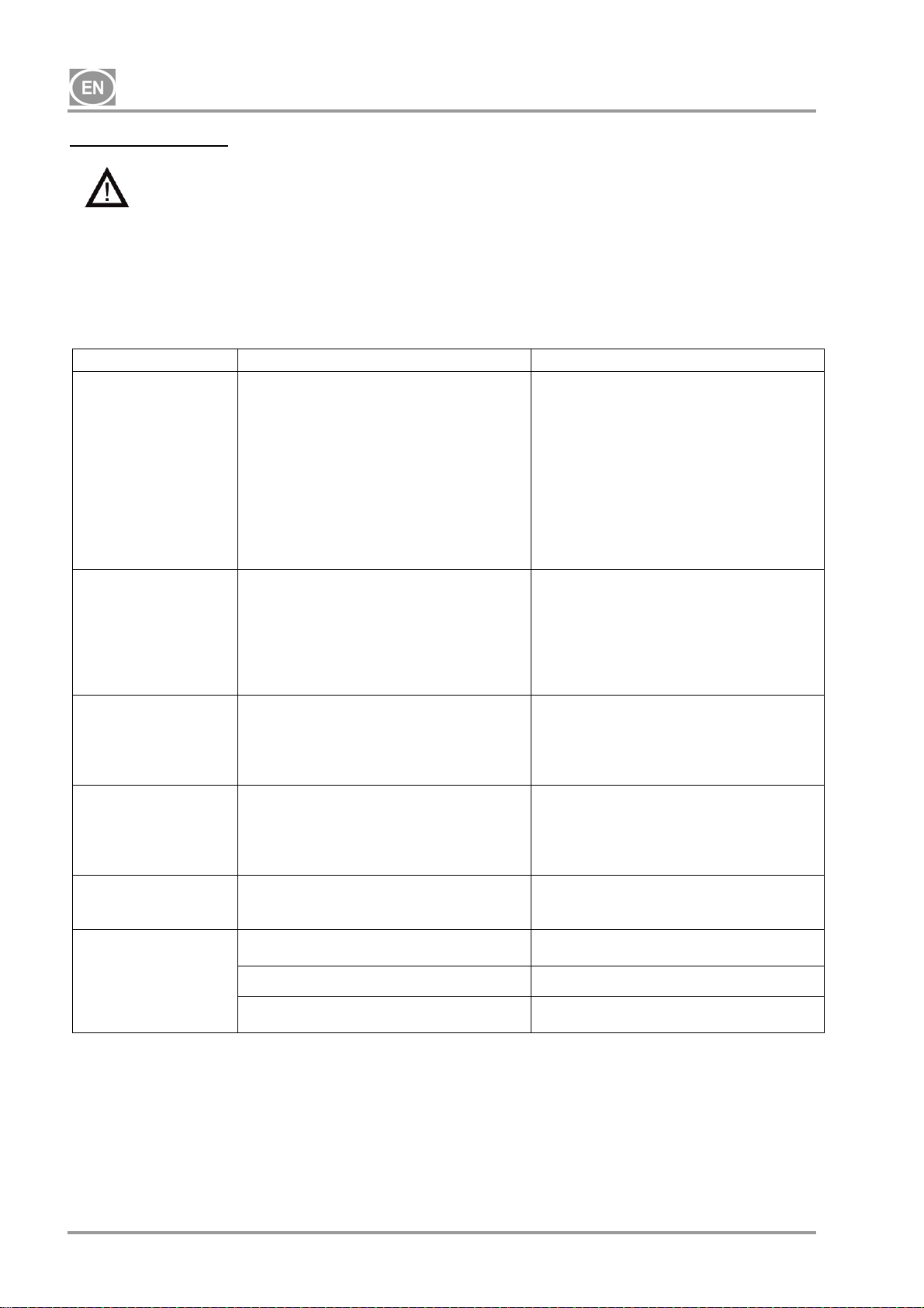
TROUBLESHOOTING
Caution! Before proceeding, depressurize the air tank to zero and disconnect the
appliance from the mains.
For permanently high efficiency of drying, it is necessary to maintain the whole appliance, and
mainly ventilator clean – regularly clean the surface of ventilator and cooling fins of cooler.
Troubleshooting can be performed only by qualified personnel.
MALFUNCTIONS POSSIBLE CAUSE REMEDY
Compressor does not
start
Compressor often
switches on
Low pressure in air
tank (compressor
running constantly)
Prolonged operation
of the compressor
Compressor is noisy
(knocking, metal
noises)
Dryer doesn't dry
(condensed water in
the air) *
No voltage at the pressure switch
Check voltage in socket
Check the circuit breaker – switch into the
“I” on position
Loose conductor at terminal – tighten
Check the electrical cord – replace
defective cord
Motor winding failure, damaged
thermal overload protection
Faulty capacitor
Seized piston or other rotating part
Pressure switch does not switch
Air leak in compressed air distribution
system
Leaking check valve
Large volume of condensed liquid in
pressure vessel
Replace motor or windings
Replace capacitor
Replace damaged parts
Check the function of the pressure switch
Check compressed air distribution
system – seal loose joints
Clean solenoid valve, replace seals,
replace solenoid valve
Drain condensed liquid
Check the time to fill the air tank
Low compressor performance
High air usage by appliance, Leak in
compressed air system, Low aggregate
output
Aggregate malfunction
Dryer malfunction
Air leak in compressed air distribution
system
Worn piston ring
Inlet filter is plugged
Defective solenoid valve
Damaged piston bearing, piston rod,
motor bearing
Loose or cracked spring
Check compressed air distribution
system – seal loose joint
Replace worn piston ring
Replace old filter with a new filter
Repair or change the valve or coil
Replace damaged bearing
Replace damaged spring
Cooling fan not working Replace the fan
Check the power source
Damaged dryer Replace the dryer
Non-functioning automatic condensate
Clean / replace
drain - clean / replace on the filter
)* After a dryer malfunction, the interior surfaces of the air tank must be thoroughly cleaned and all
condensed liquid removed.
Check the dew point of the air leaving the air tank (see Chapter 5 - Technical data) to protect the
equipment from damage!
NP-DK50-1_08-2017-MD - 28 - 08/2017
Page 31

DK50-10
19. REPAIR SERVICE
Guaranteed and post-guarantee repairs must be done by the manufacturer, its authorized representative, or
service personnel approved by the supplier.
The manufacturer reserves the right to make changes to the appliance without notice. Any changes
made will not affect the functional properties of the appliance.
20. STORAGE
If the compressor will not be used for a prolonged time period, drain all condensate from the air tank. Then
turn on the compressor for 10 minutes, keeping the drain valve open (1) (Fig. 11). Switch off the compressor
using the switch (3) at the pressure switch (2) (Fig. 9), close the drain valve and disconnect the appliance
from the mains.
21. DISPOSING OF THE APPLIANCE
Disconnect the appliance from the mains.
Release air pressure in the pressure tank by opening the drain valve (1) (Fig. 11).
Dispose of the equipment following all applicable environmental regulations.
Entrust a specialised company to sort and dispose of waste.
Worn out components have no negative environmental impact.
08/2017 - 29 - NP-DK50-1_08-2017-MD
Page 32

DK50-10
INHALT
WICHTIGE INFORMATIONEN ............................................................................................................. 31
1. CE-KENNZEICHNUNG ............................................................................................................ 31
2. WARNHINWEISE ..................................................................................................................... 31
3. WARNHINWEISE UND -SYMBOLE ......................................................................................... 32
4. LAGER- UND TRANSPORTBEDINGUNGEN .......................................................................... 33
5. TECHNISCHE DATEN ............................................................................................................. 34
6. PRODUKTBESCHREIBUNG .................................................................................................... 37
7. PRODUKTFUNKTION .............................................................................................................. 39
8. PNEUMATISCHES SCHEMA ................................................................................................... 43
BEDIENUNG ......................................................................................................................................... 44
9. EINSCHALTEN DES KOMPRESSORS ................................................................................... 44
INSTALLATION ..................................................................................................................................... 45
10.EINSATZBEDINGUNGEN ........................................................................................................ 45
11.AUFSTELLUNG DES KOMPRESSORS .................................................................................. 46
12.PNEUMATISCHE ANSCHLÜSSE ............................................................................................ 47
13.ELEKTRISCHE ANSCHLÜSSE ................................................................................................ 47
14.ANSCHLUSSPLAN ................................................................................................................... 48
15.INBETRIEBNAHME .................................................................................................................. 50
16.EINSCHALTEN DES KOMPRESSORS ................................................................................... 50
17.ABSCHALTEN DES KOMPRESSORS .................................................................................... 50
WARTUNG ............................................................................................................................................ 51
18.GERÄTEWARTUNG ................................................................................................................. 51
FEHLERBEHEBUNG ............................................................................................................................ 56
19.INFORMATIONEN ZU REPARATURBETRIEBEN .................................................................. 57
20.LAGERUNG .............................................................................................................................. 57
21.ENTSORGUNG DES GERÄTS ................................................................................................ 57
ANHANG ............................................................................................................................................. 198
22.INSTALLATIONSPROTOKOLL .............................................................................................. 199
NP-DK50-1_08-2017-MD - 30 - 08/2017
Page 33

DK50-10
WICHTIGE INFORMATIONEN
1. CE-KENNZEICHNUNG
Die Produkte mit CE-Kennzeichnung erfüllen die Sicherheitsrichtlinien der Europäischen Union
(93/42/EEC).
2. WARNHINWEISE
Das Produkt ist so ausgelegt und wurde so hergestellt, dass der Benutzer und die Umgebung sicher sind,
wenn das Produkt ordnungsgemäß genutzt wird. Beachten Sie die folgenden Warnhinweise, um Risiken zu
minimieren.
2.1. Allgemeine Warnhinweise
Das Benutzerhandbuch gibt Anleitungen zur korrekten Installation, Bedienung und Wartung des
Produkts. Es ist Bestandteil des Produkts und der Benutzer muss jederzeit darauf zugreifen können.
Lesen Sie dieses Handbuch sorgfältig und aufmerksam durch, um das Produkt korrekt zu betreiben.
Die Originalverpackung sollte für die Rücksendung des Geräts aufbewahrt werden. Nur die
Originalverpackung garantiert den optimalen Transportschutz des Geräts. Falls eine Einsendung des
Produkts während der Garantiezeit notwendig werden sollte, haftet der Hersteller nicht für Schäden, die
auf eine mangelhafte Verpackung zurückzuführen sind.
Die Gewährleistung deckt keine Schäden, die aufgrund der Nutzung von Zubehör oder
Verbrauchsmaterialien entstanden sind, die von den durch den Hersteller festgelegten oder empfohlenen
Produkten abweichen.
Der Hersteller garantiert die Sicherheit, Zuverlässigkeit und Funktion des Geräts nur, wenn:
- Montage, Neueinstellungen, Änderungen, Erweiterung und Reparaturen durch den Hersteller oder
einen durch den Hersteller autorisierten Dienstleister erfolgen.
- das Produkt gemäß den Vorgaben des Benutzerhandbuchs verwendet wird.
Das Benutzerhandbuch entspricht im Zeitpunkt seines Drucks der Konfiguration des Produkts und
dessen Erfüllung der geltenden Sicherheits- und Technikstandards. Der Hersteller behält alle Rechte an
den Konfigurationen, Verfahren und Namen.
Die Übersetzung des Benutzerhandbuchs erfolgt nach bestem Wissen. Bei Unsicherheiten gilt die
slowakische Version.
2.2. Allgemeine Sicherheitshinweise
Der Hersteller hat das Produkt so konzipiert und hergestellt, dass bei korrekter Nutzung die Risiken minimal
sind. Beachten Sie folgende Sicherheitsmaßnahmen, um Risiken zu minimieren.
Die Nutzung und Bedienung des Produkts muss alle lokalen Bestimmungen und Vorschriften erfüllen.
Der Bediener und Nutzer des Produkts muss alle gültigen Vorschriften einhalten, um eine sichere Arbeit
zu gewährleisten.
Nur die Nutzung von Originalteilen gewährleistet die Sicherheit des Bedienpersonals und eine
reibungslose Funktion des Produkts selbst. Es dürfen nur Zubehör- und Ersatzteile verwendet werden,
die in der technischen Dokumentation aufgeführt oder ausdrücklich vom Hersteller zugelassen sind.
Der Bediener muss vor jeder Nutzung die korrekte und sichere Funktion des Geräts überprüfen.
Der Nutzer muss sich mit der Gerätebedienung vertraut gemacht haben.
Verwenden Sie das Produkt nicht in explosionsgefährdeten Bereichen.
Tritt während der Nutzung des Geräts ein Problem auf, muss der Benutzer den Lieferanten umgehend
benachrichtigen.
08/2017 - 31 - NP-DK50-1_08-2017-MD
Page 34
DK50-10
2.3. Elektrosystem – Sicherheitshinweise
Das Gerät darf nur an eine ordnungsgemäß installierte Steckdose mit Erdung angeschlossen werden.
Vor dem Anschluss des Produkts muss kontrolliert werden, ob die auf dem Gerät angegebene
Netzspannung und Netzfrequenz mit den Werten des Versorgungsnetzes übereinstimmen.
Überprüfen Sie vor der Nutzung das angeschlossene Druckluftsystem und den Stromkreis auf mögliche
Schäden. Beschädigte Druckluftschläuche und Stromkabel sind sofort zu ersetzen.
Trennen Sie das Produkt sofort vom Stromnetz (ziehen Sie dazu das Netzkabel aus der Steckdose),
wenn eine Gefahrensituation oder ein technischer Fehler auftritt.
Stellen Sie bei Wartungs- und Reparaturarbeiten sicher, dass folgende Schritte ausgeführt wurden:
- der Netzstecker wurde aus der Steckdose gezogen
- der Druck wurde aus den Druckluftleitungen und dem Drucklufttank abgelassen
Das Produkt darf nur durch einen qualifizierten Techniker installiert werden.
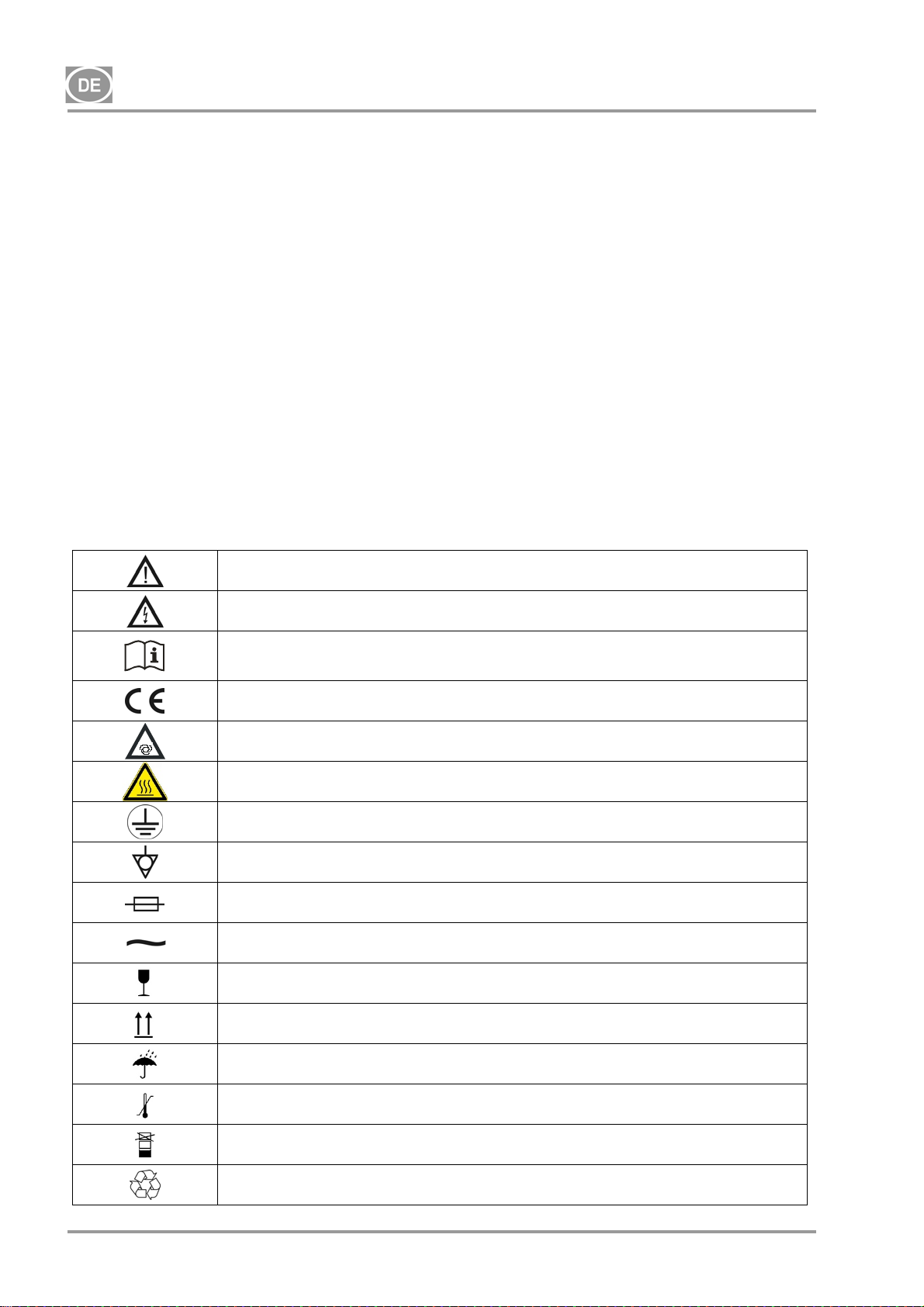
3. WARNHINWEISE UND -SYMBOLE
Die folgenden Etiketten und Symbole werden im Benutzerhandbuch, auf dem Gerät und auf der Verpackung
verwendet, um auf wichtige Details und Informationen hinzuweisen:
Hinweise, Anweisungen und Verbote, um Gesundheits- oder Sachschäden zu
vermeiden
Vorsicht! Gefährliche elektrische Spannung
Lesen Sie das Benutzerhandbuch!
CE-Konformitätskennzeichnung
Vorsicht! Heiße Oberfläche
Der Kompressor wird fernbedient und kann ohne Warnung starten
Erdungsanschluss
Klemme für Erdungsanschluss
Sicherung
Wechselstrom
Handhabungshinweis auf Verpackung – ZERBRECHLICH
Handhabungshinweis auf Verpackung – HIER OBEN
NP-DK50-1_08-2017-MD - 32 - 08/2017
Handhabungshinweis auf Verpackung – VOR NÄSSE SCHÜTZEN
Handhabungshinweis auf Verpackung – ZULÄSSIGE TEMPERATURBEREICHE
Handhabungshinweis auf Verpackung – BESCHRÄNKT STAPELBAR
Hinweis auf Verpackung – RECYCELBARES MATERIAL
Page 35
DK50-10
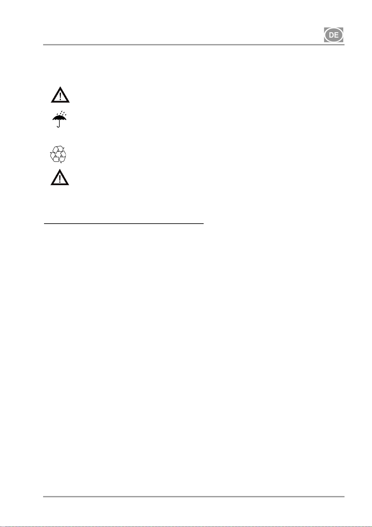
4. LAGER- UND TRANSPORTBEDINGUNGEN
Der Kompressor wird vom Hersteller in einer Transportverpackung geliefert, um das Gerät gegen
Transportschäden zu sichern.
Vorsicht! Beim Transport immer die Originalverpackung verwenden und den Kompressor
in aufrechter Position sichern.
Während des Transports und der Lagerung ist der Kompressor vor Feuchtigkeit und extremen
Temperaturen zu schützen. Kompressoren in Originalverpackung müssen in warmen, trockenen
Umgebungsbedingungen für Lagerung und Transport
und staubfreien Räumen gelagert werden. Nicht in der Nähe von chemischen Substanzen
lagern.
Bewahren Sie das Verpackungsmaterial nach Möglichkeit auf. Sollte dies nicht möglich sein,
entsorgen Sie das Verpackungsmaterial auf umweltfreundliche Art und recyceln Sie es wenn
möglich.
Vorsicht! Der Kompressor darf nur drucklos transportiert werden. Vor dem Transport
stets die Druckluft aus dem Druckbehälter und den Druckschläuchen ablassen; zusätzlich
das Kondensat entleeren.
Die Produkte dürfen nur unter den folgenden Bedingungen in Fahrzeugen gelagert und transportiert werden,
die keine Spuren flüchtiger Chemikalien aufweisen:
Temperatur: -25 °C bis +55 °C, 24 Std. bis +70 °C
Relative Feuchtigkeit: 10 % bis 90 % (nicht kondensierend)
08/2017 - 33 - NP-DK50-1_08-2017-MD
Page 36
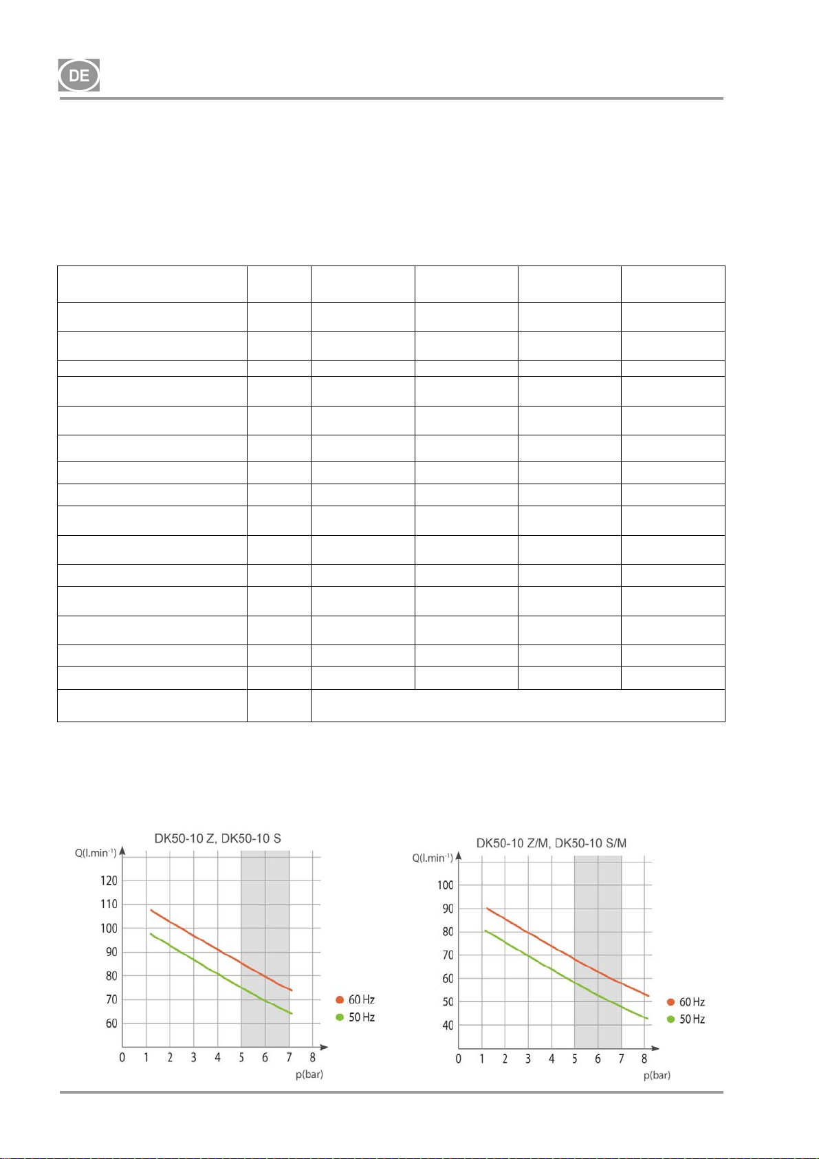
DK50-10
5. TECHNISCHE DATEN
Die Kompressoren wurden für trockene und belüftete Innenräume mit den folgenden Bedingungen
entwickelt:
Temperatur: +5 °C bis +40 °C,
Max. relative Feuchtigkeit: 70 %,
Max. absolute Feuchtigkeit: 15 g/m
Tab.1
3
5 – 7 bar
Nennspannung / Frequenz (*) V / Hz
Ausgangsleistung
bei 5 bar
Arbeitsdruck (**) bar 5,0 – 7,0 5,0 – 7,0 5,0 – 7,0 5,0 – 7,0
Ausgangsleistung mit KJF-1
bei 5 bar
Max. Strom A
Ausgangsleistung Motor kW 0,55 0,55 0,55 0,55
Volumen Drucklufttank Lit. 10 10 10 10
Luftqualität – Filterung
Max. Betriebsdruck des
Sicherheitsventils
Geräuschpegel bei 5 bar LpfA [dB]
Betriebsmodus 100 % - S 1 100 % - S 1 100 % - S 1 100 % - S 1
PDP-Trocknungsleistung bei 7
bar
Zeit, den Druckluftspeicher von
0 bis 6 bar zu füllen
Maße (netto) B x T x H mm 485x350x553 580x440x655 544x350x553 649x440x655
Nettogewicht kg
Konfiguration nach
EN 60601-1
Liter min-
1
Liter min-
1
m
bar 8,0 8,0 8,0 8,0
- -
S
Typ B, Klasse I.
DK50-10 Z DK50-10 S DK50-10 Z/M
230 / 50/60
115 / 60
75 – 85
85
75 – 85
85
3,8 – 4,8
9,5
- - 0,3 0,3
65 – 66,5
66,5
50 – 44
44
38 (
***) 53 (***)
230 / 50/60
115 / 60
75 – 85
85
75 – 85
85
3,8 – 4,8
9,5
49,5 – 51
51
50 – 44
44
230 / 50/60
115 / 60
58 – 68
68
- -
4,1 – 5,1
10
67 – 68,5
68,5
+3 °C
70 – 60
60
44
DK50-10 S/M
230 / 50/60
115 / 60
58 – 68
68
4,1 – 5,1
10
51,5 – 53
53
+3 °C
70 – 60
60
61
Hinweise:
(*) Bei Bestellung gewünschte Ausführung des Kompressors angeben
(**) Druckbereich: Lieferant konsultieren
(***) Kompressorgewicht mit einer KJF-1-Einheit _plus 3 kg
(****) Der zulässige Betriebsdruck des Sicherheitsventils kann auch auf einen anderen Wert eingestellt
werden, z. B. auf 9 bar / die Einstellung ist im Auftrag anzugeben.
NP-DK50-1_08-2017-MD - 34 - 08/2017
Page 37
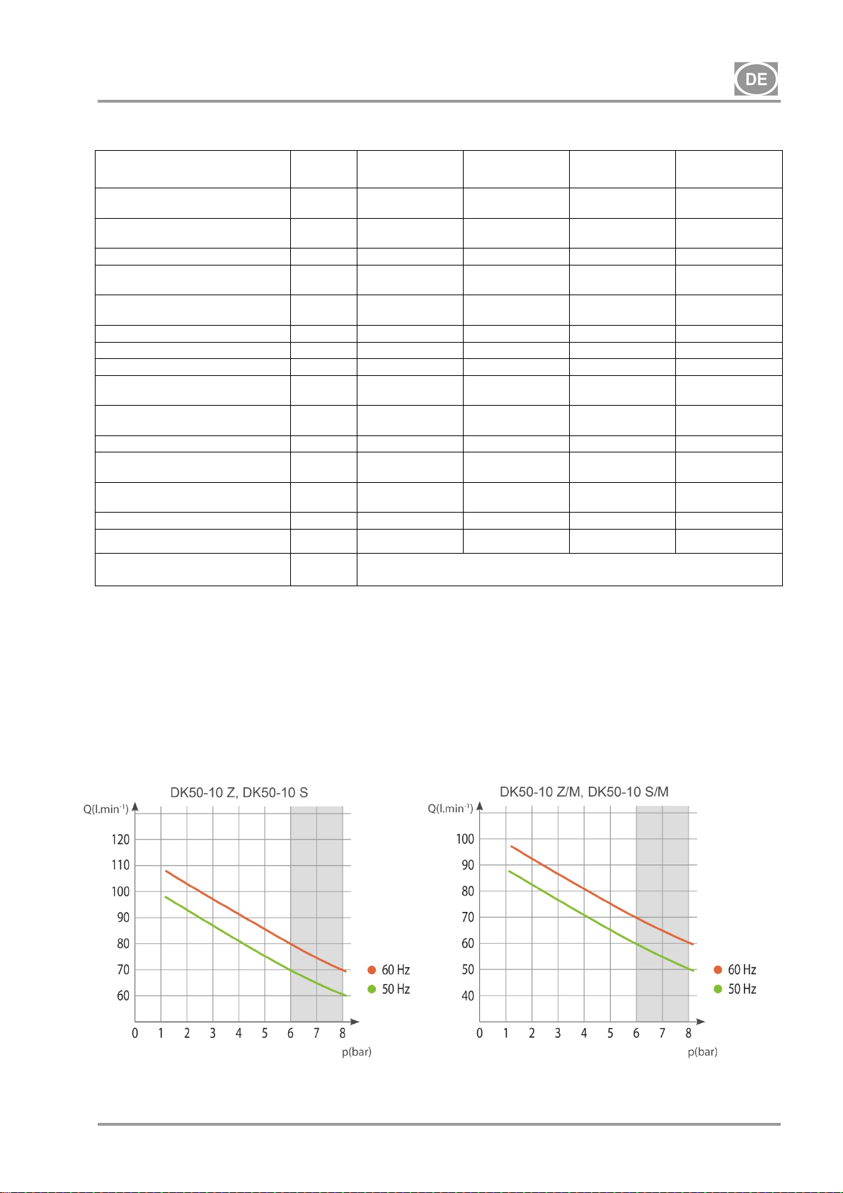
DK50-10
Tab. 2
6 – 8 bar
Nennspannung / Frequenz (*) V / Hz
Ausgangsleistung
bei 6 bar
Arbeitsdruck (**) bar 6,0 – 8,0 6,0 – 8,0 6,0 – 8,0 6,0 – 8,0
Ausgangsleistung mit KJF-1
bei 6 bar
Max. Strom A
Ausgangsleistung Motor kW 0,55 0,55 0,55 0,55
Volumen Drucklufttank 10 10 10 10
Luftqualität – Filterung
Max. Betriebsdruck des
Sicherheitsventils
Geräuschpegel bei 5 bar LpfA [dB]
Betriebsmodus
PDP-Trocknungsleistung bei 7
bar
Zeit, den Druckluftspeicher von
0 bis 7 bar zu füllen
Maße (netto) B x T x H mm 485x350x553 580x440x655 544x350x553 649x440x655
Nettogewicht kg
Konfiguration nach
EN 60601-1
Liter min1
Liter min1
m
bar 12,0 12,0 12,0 12,0
- -
S
DK50-10 Z DK50-10 S DK50-10 Z/M
230 / 50/60
115 – 60
70 – 80
80
70 – 80
80
3,9 – 4,9
9,8
- - 0,3 0,3
65 – 66,5
66,5
100 % - S 1 100 % - S 1 100 % - S 1 100 % - S 1
60 – 51
51
38 (***) 53 (***)
230 / 50/60
115 – 60
70 – 80
80
70 – 80
80
3,9 – 4,9
9,8
49,5 – 51
51
60 – 51
51
Typ B, Klasse I.
230 / 50/60
115 – 60
60 – 70
70
- -
4,1 – 5,1
10,2
67 – 68,5
68,5
+3 °C
72 – 61
61
44
DK50-10 S/M
230 / 50/60
115 – 60
60 – 70
70
4,1 – 5,1
10,2
51,5 – 53
53
+3 °C
72 – 61
61
61
Hinweise:
(*) Bei Bestellung gewünschte Ausführung des Kompressors angeben
(**) Druckbereich: Lieferant konsultieren
(***) Kompressorgewicht mit einer KJF-1-Einheit _plus 3 kg
(****) Der zulässige Betriebsdruck des Sicherheitsventils kann auch auf einen anderen Wert eingestellt
werden, z. B. auf 9 bar / die Einstellung ist im Auftrag anzugeben.
08/2017 - 35 - NP-DK50-1_08-2017-MD
Page 38
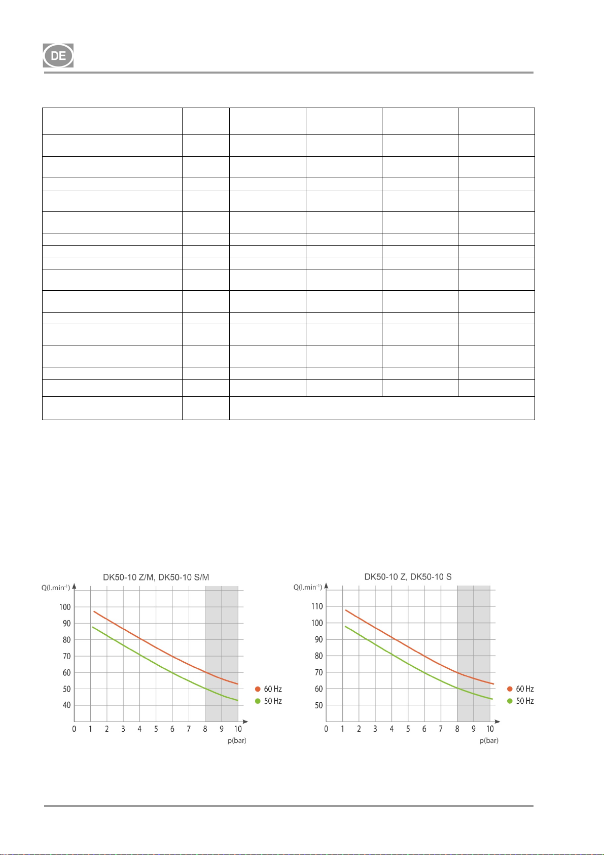
DK50-10
Tab. 3
8 – 10 bar
Nennspannung / Frequenz (*) V / Hz
Ausgangsleistung
bei 8 bar
Arbeitsdruck (**) bar 8,0 – 10,0 8,0 – 10,0 8,0 – 10,0 8,0 – 10,0
Ausgangsleistung mit KJF-1
bei 8 bar
Max. Strom A
Ausgangsleistung Motor kW 0,55 0,55 0,55 0,55
Volumen Drucklufttank 10 10 10 10
Luftqualität – Filterung
Max. Betriebsdruck des
Sicherheitsventils
Geräuschpegel bei 5 bar LpfA [dB]
Betriebsmodus
PDP-Trocknungsleistung bei 7
bar
Zeit, den Druckluftspeicher von
0 bis 9 bar zu füllen
Maße (netto) B x T x H mm 485x350x553 580x440x655 544x350x553 649x440x655
Nettogewicht kg
Konfiguration nach
EN 60601-1
Liter min1
Liter min1
m
bar 12,0 12,0 12,0 12,0
- -
S
DK50-10 Z DK50-10 S DK50-10 Z/M
230 / 50/60
115 – 60
60 – 70
70
60 – 70
70
4,1 – 5,1
10,2
- - 0,3 0,3
65 – 66,5
66,5
100 % - S 1 100 % - S 1 100 % - S 1 100 % - S 1
85 – 75
75
38 (***) 53 (***)
230 / 50/60
115 – 60
60 – 70
70
60 – 70
70
4,1 – 5,1
10,2
49,5 – 51
51
85 – 75
75
Typ B, Klasse I.
230 / 50/60
115 – 60
50 – 60
60
- -
4 5,3
10,5
67 – 68,5
68,5
+3 °C
96 – 82
82
44
DK50-10 S/M
230 / 50/60
115 – 60
50 – 60
60
4,4 – 5,4
10,5
51,5 – 53
53
+3 °C
96 – 82
82
61
Hinweise:
(*) Bei Bestellung gewünschte Ausführung des Kompressors angeben
(**) Druckbereich: Lieferant konsultieren
(***) Kompressorgewicht mit einer KJF-1-Einheit _plus 3 kg
(****) Der zulässige Betriebsdruck des Sicherheitsventils kann auch auf einen anderen Wert eingestellt
werden, z. B. auf 9 bar / die Einstellung ist im Auftrag anzugeben.
NP-DK50-1_08-2017-MD - 36 - 08/2017
Page 39
DK50-10
5.1. Korrektur des Luftfördervolumens (Free Air Delivery; FAD) unter Berücksichtigung der
Höhe über dem Meeresspiegel
FAD-Korrekturtabelle
Höhe über dem
Meeresspiegel in
Metern [m ü. NHN]
FAD [l/min] FAD x 1 FAD x 0,8 FAD x 0,71 FAD x 0,60
FAD-Ausgang in Bezug auf die Bedingungen:
Höhendaten: 0 m ü. NHN Temperatur: 20 °C
Umgebungsdruck: 101325 Pa Relative Feuchtigkeit: 0 %
6. PRODUKTBESCHREIBUNG
6.1. Modellvarianten und deren Anwendungsmöglichkeiten
0 – 1500 1501 – 2500 2501 – 3500 3501 – 4500
Der Kompressor wird als Quelle für saubere, ölfreie Druckluft für den Betrieb von Dentalausrüstungen,
Instrumenten und Geräten in Laboren verwendet, wo die Parameter und Eigenschaften der Druckluft für die
jeweilige Anwendung des Kompressors geeignet sind.
Die durch den Kompressor bereitgestellte Druckluft ist nicht für die Nutzung mit Geräten zur
künstlichen Beatmung geeignet, ohne dass zuvor eine weitere Filterung erfolgte.
Jede Nutzung des Geräts, die nicht dem hier definierten Umfang entspricht, ist eine unsachgemäße
Nutzung. Der Hersteller haftet nicht für Schäden oder Verletzungen aufgrund einer unsachgemäßen
Nutzung.
6.2. Beschreibung
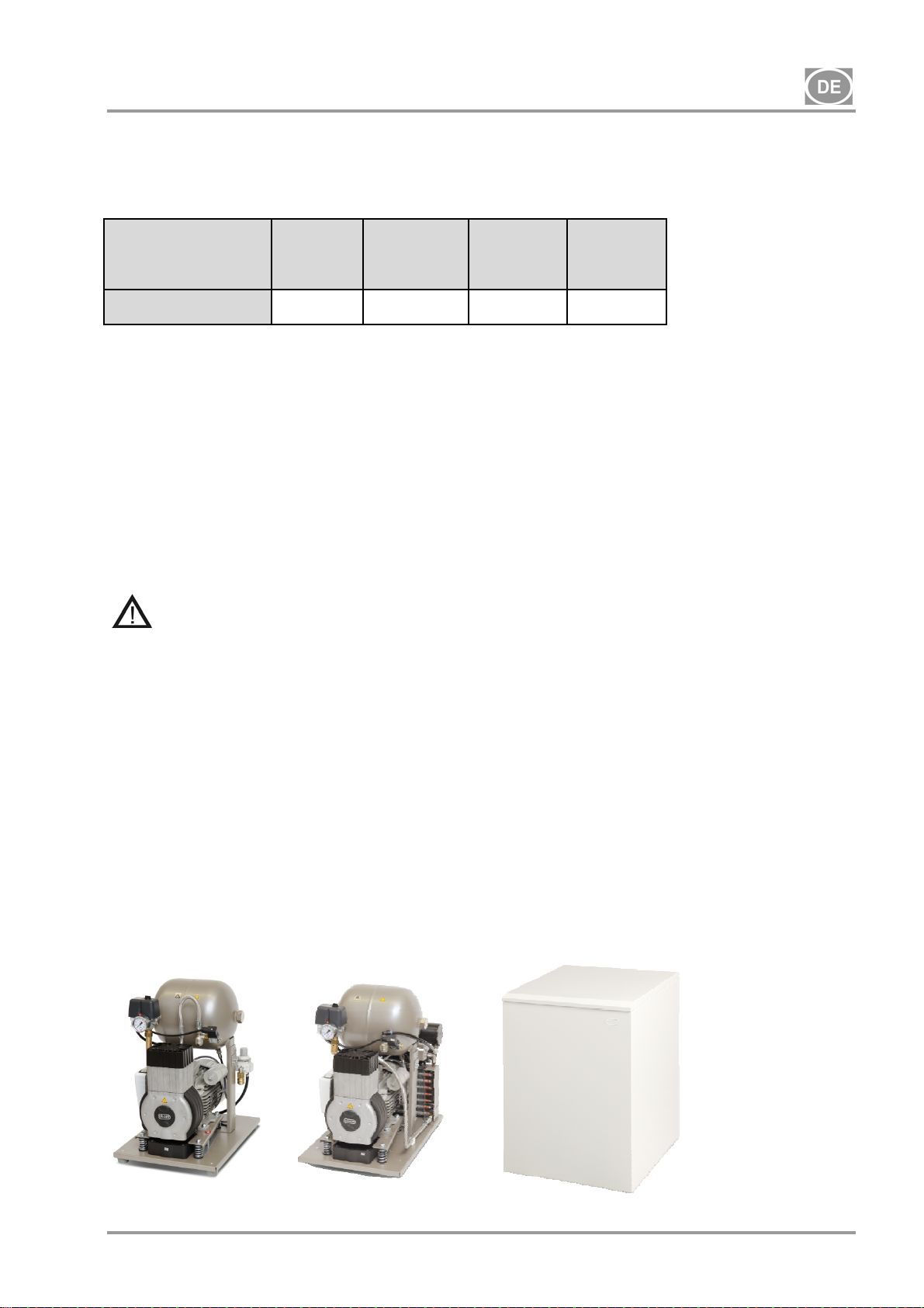
Die Kompressoren wurden für folgende Verwendungszwecke hergestellt:
DK50-10 Z-Kompressor Kompressor für die Bodenmontage und alleinstehende Installation in einem
Bereich
DK50-10 Z/K-Kompressor Kompressor für die Bodenmontage mit Kondensat- und Filtereinheit (KJF-1)
DK50-10 Z/M-Kompressor Kompressor für die Bodenmontage mit Lufttrockner
DK50-10 S-Kompressor Umschlossener Kompressor mit effektiver Geräuschdämpfung für die
Installation in Büroräumen
DK50-10 S/K-Kompressor Umschlossener Kompressor mit Kondensat- und Filtereinheit (KJF-1)
DK50-10 S/M-Kompressor Umschlossener Kompressor mit Lufttrockner
DK50-10 Z
08/2017 - 37 - NP-DK50-1_08-2017-MD
DK50-10 Z/M
DK50-10 S
DK50-10 S/M
Page 40
DK50-10
6.3. Zubehör
Zubehör, das nicht Teil der standardmäßigen Bestellung ist, muss separat bestellt werden.
6.3.1 Automatischer Kondensatablauf
Der automatische Kondensatablauf (Automatic Condensate Drain; AOK) lässt das Kondensat automatisch
und gemäß einem vorgegebenen Zeitintervall aus dem Kompressor-Luftbehälter ab. Der Kondensatablauf
(AOK) ist ein geeignetes Zubehörteil für Kompressormodelle ohne Trockner.
6.3.2 Filtersatz
Bei entsprechendem Hinweis können Kompressoren mit einem Filtersatz am Druckluftausgang ausgestattet
werden. Der Filtersatz kann mit einem Druckregler ausgestattet werden. Filtersätze sind ein geeignetes
Zubehör für alle oben aufgeführten Kompressoren.
HINWEIS: Ist ein höherer Grad an Luftfilterung nötig, muss dies im Vorfeld mit dem Lieferanten vereinbart
und in der Bestellung klar angegeben werden.
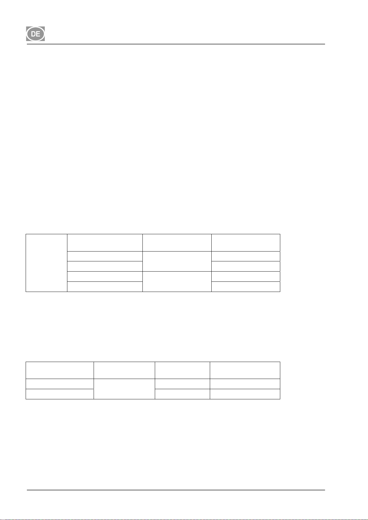
Grad der Luftfilterung Druckregler Artikelnr. Satz
-
FILTERSATZ
6.3.3 Kondensat- und Filtereinheit (KJF)
Der Kompressor kann zusätzlich mit einer Kondensat- und Filtereinheit (KJF-1 oder KJFR-1) ausgestattet
werden. Die Einheiten KJF-1 oder KJFR-1 sorgen dafür, dass die Druckluft des Drucklufttanks im Kühler
gekühlt und das Kondensat im Filter gesammelt und automatisch aus dem Druckluftkreislauf entfernt wird.
Gleichzeitig wird die Druckluft gefiltert.
Kondensat- und
Filtereinheit
KJF-1
KJFR-1 Ja 450001011-002
5 µm 604013233-000
0,3 µm
0,01 µm 604013235-000
Grad der
Luftfilterung
5µm
Ja
Nein
Druckregler Artikelnr. Satz
Nein 450001011-001
604013245-000
604013234-000
NP-DK50-1_08-2017-MD - 38 - 08/2017
Page 41
DK50-10
7. PRODUKTFUNKTION
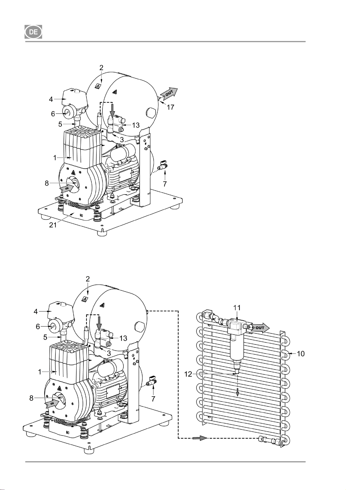
Kompressor (Abb. 1)
Der Kompressor (1) saugt Luft durch einen Ansaugfilter (8) an und drückt sie durch ein Rückschlagventil (3)
in einen Luftbehälter (2), aus dem das Gerät Druckluft bezieht. Wenn der Druck im Luftbehälter auf den
Schaltdruck fällt, schaltet der Druckschalter (4) den Kompressor ein und der Kompressor leitet Druckluft in
den Luftbehälter, bis der Ausschaltdruck erreicht wird und der Kompressor daraufhin abschaltet. Der
Druckschlauch wird durch das Ablassmagnetventil (13) entlüftet, sobald der Kompressor abgeschaltet ist.
Das Sicherheitsventil (5) verhindert, dass der Druck im Luftbehälter über den maximal zulässigen Wert
hinaus ansteigt. Das Kondenswasser wird durch das Ablassventil (7) aus dem Luftbehälter abgelassen.
Ölfreie Druckluft steht im Druckluftbehälter zur weiteren Nutzung bereit.
Das Kondensat muss in regelmäßigen Intervallen aus dem Druckluftbehälter abgelassen werden (siehe
Kapitel 18).
Kompressor mit Membrantrockner (Abb. 3)
Das Kompressoraggregat (1) zieht Außenluft durch einen Ansaugfilter (8) ein und komprimiert sie. Dann
wird die Luft zum Kühler (14) durch den Filter (15) zum Trockner (9) gespeist, anschließend wird die
trockene, saubere Luft durch das Absperrventil (3) in den Luftbehälter (2) eingespeist. Ein Teil der Luft
strömt an dem Trockner mit der erfassten Feuchtigkeit vorbei und macht sich als leichter Luftstrom entlang
des Trocknergehäuses (9) bemerkbar. Das Kondensat aus dem Filter wird automatisch in regelmäßigen
Intervallen über das Kondensatablassmagnetventil (16) in den Behälter abgeleitet. Der Trockner sorgt dafür,
dass die Druckluft ständig getrocknet wird. Das Kondenswasser wird durch das Ablassventil (7) aus dem
Luftbehälter abgelassen, wenn die Trocknerleistung überprüft wird. Ölfreie Druckluft steht im
Druckluftbehälter zur weiteren Nutzung bereit.
Der Kompressor mit Trockner erfordert keinen Bediener. Der Druckbehälter muss nicht abgelassen werden.
Kompressor mit Kondensations- und Filtrationseinheit (Abb. 2)
Das Kompressoraggregat (1) saugt Luft durch einen Ansaugfilter (8) an und drückt sie durch ein
Rückschlagventil (3) in einen Luftbehälter (2). Druckluft aus dem Luftbehälter strömt durch einen Kühler
(10), der die Druckluft kühlt. Die kondensierte Feuchtigkeit wird im Filter (11) erfasst und automatisch als
Kondensat (12) in den Behälter abgeschieden. Ölfreie gefilterte Druckluft steht zur weiteren Nutzung bereit.
Das Kondensat muss in regelmäßigen Intervallen aus dem Druckluftbehälter abgelassen werden (siehe
Kapitel 18).
Kompressorgehäuse
Das schalldichte Gehäuse ist kompakt und ermöglicht einen ausreichenden Austausch der Kühlluft. Das
Design eignet sich für die Aufstellung des Kompressors in Büros und fügt sich in die Möblierung ein. Der
Lüfter unter dem Kompressoraggregat sorgt für ausreichende Kühlung des Lüfters und läuft mit dem
Kompressormotor oder wenn der Temperaturschalter bei Temperaturen über 40 °C aktiviert wird.
Stellen Sie sicher, dass der Luftstrom unter und rund um den Kompressor nicht
beeinträchtigt wird. Bedecken Sie niemals den Warmluftausgang an der oberen Rückseite
des Gehäuses.
Wird der Kompressor auf eine weiche Unterlage (z.B. auf einen Teppich) gestellt, ist es
nötig, durch harte Unterlagen einen ausreichenden Abstand zwischen der Basis und dem
Boden zu gewährleisten, um eine entsprechende Kühlleistung zu garantieren.
Das Kompressormodell mit 10 bar ist mit einem Stundenzähler (Abb. 4) ausgestattet.
08/2017 - 39 - NP-DK50-1_08-2017-MD
Page 42
DK50-10
Abb. 1 – DK50-10 Z Kompressor
Abb. 2 – DK50-10 Z/K Kompressor mit KJF-1-Kondensat- und Filtrationseinheit
Beschreibung für
Abbildungen 14
1. Kompressoraggregat
2. Luftbehälter
3. Rückschlagventil
4. Druckschalter
5. Sicherheitsventil
6. Manometer
7. Ablassventil
8. Ansaugfilter
9. Trockner
10. Röhrenkühler
11. Filter
12. Kondensatablass
13. Magnetventil
14. Trocknerkühler
15. Filter
16. Ventil mit Timer
17. Druckluftausgang
18. Trennschalter
19. Behälter
20. Magnetklammer
21. Lüfter
22. Schalter
23. Stundenzähler
24. Verbinder
25. Boxenlüfter
NP-DK50-1_08-2017-MD - 40 - 08/2017
Page 43
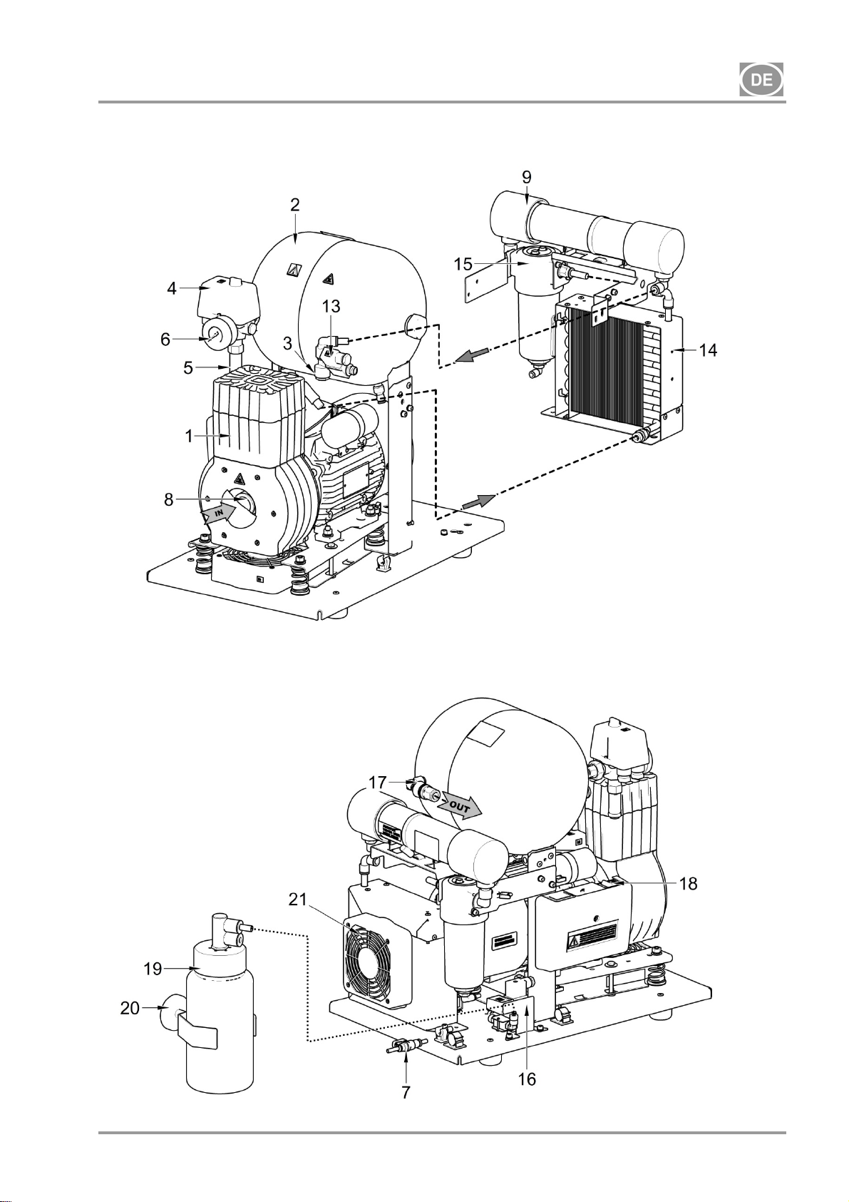
DK50-10
Abb. 3 – DK50-10 Z/M Kompressor mit Trockner
08/2017 - 41 - NP-DK50-1_08-2017-MD
Page 44
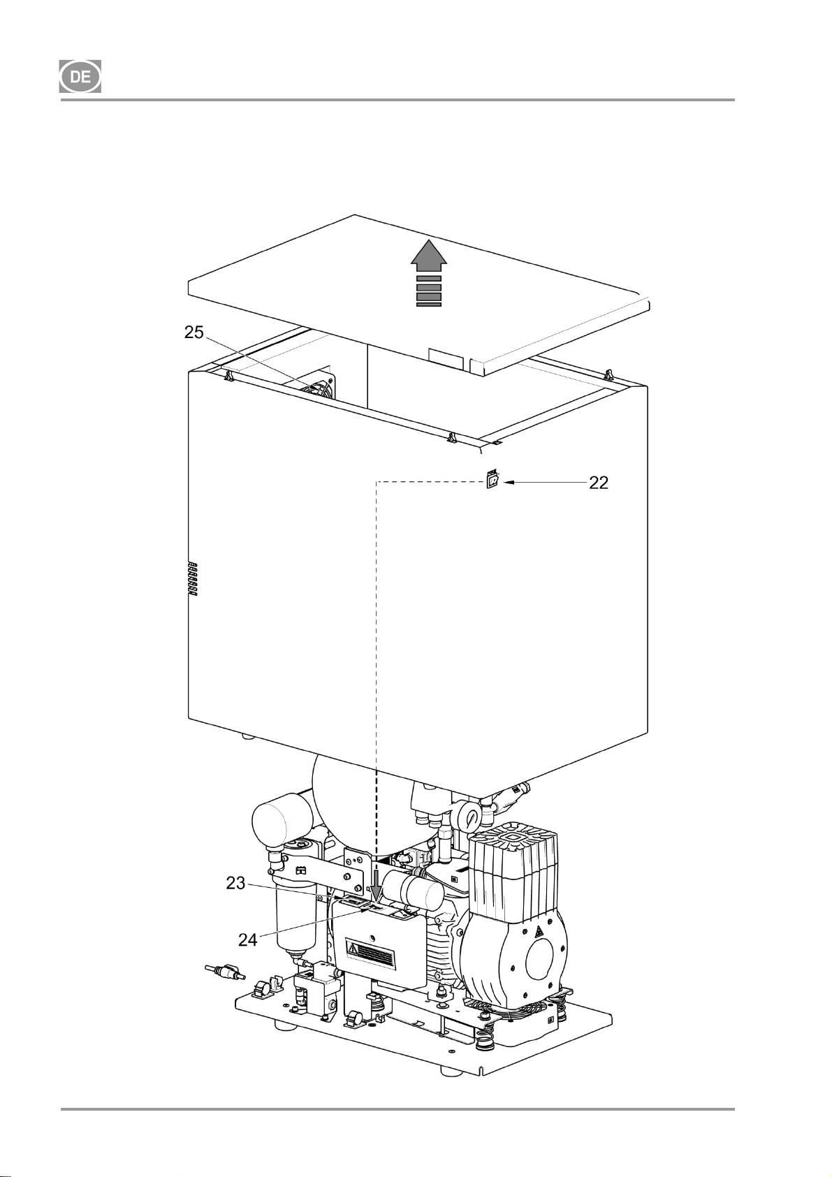
DK50-10
Abb. 4 – Kompressor DK50-10 S/M 10 bar
NP-DK50-1_08-2017-MD - 42 - 08/2017
Page 45
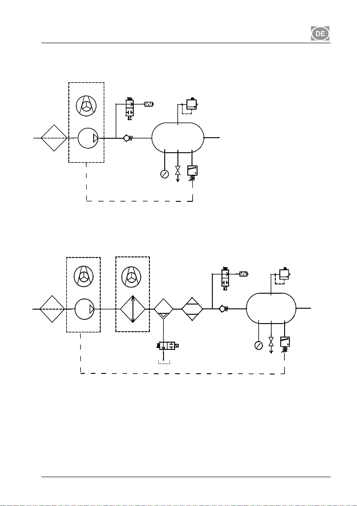
DK50-10
8. PNEUMATISCHES SCHEMA
DK50-10 Z, DK50-10 S
1
DK50-10 Z/M, DK50-10 S/M
1
Legende für Druckluft-Schemata
1. Ansaugfilter
2. Kompressor
3. Lüfter
4. Ablassventil
5. Geräuschdämpfer
6. Rückschlagventil
7. Manometer
8. Druckschalter
3
4
2
6
3
2
12
14
9
8
4
6
5
10
11
7
9
8
5
10
11
7
3
13
16
15
9. Sicherheitsventil
10. Luftbehälter
11. Ablassventil
12. Kühler
13. Koaleszenzfilter
14. Membrantrockner
15. Kondensatbehälter
16. Kondensatablass-Magnetventil
08/2017 - 43 - NP-DK50-1_08-2017-MD
Page 46
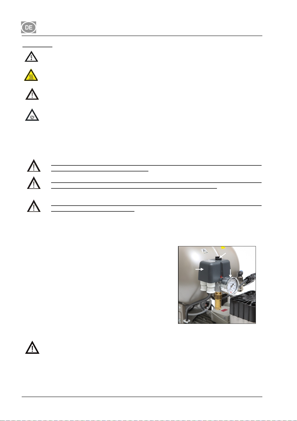
DK50-10
BEDIENUNG
Bei Gefahr das Gerät vom Stromnetz trennen (Netzstecker ziehen).
Kompressorteile werden sehr heiß.
Bei Kontakt können Verbrennungen oder Feuer die Folge sein.
Bei längerem Betrieb des Kompressors erhöht sich die Temperatur im Gehäuse auf über
Die Einstellungen des Arbeitsdrucks für den Druckschalter, die vom Hersteller eingestellt sind, können
nicht geändert werden. Der Kompressorbetrieb bei einem Betriebsdruck unter dem Schaltdruck weist auf
einen hohen Luftverbrauch durch die angeschlossene Vorrichtung hin (siehe Kapitel Störungen)
9. EINSCHALTEN DES KOMPRESSORS
40 °C und der Kühlventilator schaltet sich automatisch ein. Kühlt die Temperatur im
Gehäuse unter etwa 32 °C ab, schaltet sich der Kühlventilator wieder aus.
Automatischer Betrieb des Produkts – Sinkt der Druck im Druckbehälter auf den
Einschaltdruck, wird der Kompressor automatisch eingeschaltet. Der Kompressor
schaltet sich nach Erreichen des oberen Druckpegels automatisch aus.
Die benötigte Trocknungsleistung kann nur erreicht werden, wenn die festgelegten
Bedienbedingungen eingehalten werden.
Die Trocknungsleistung lässt nach und der erreichte Taupunkt fällt, wenn der Trockner
bei einem Druck unterhalb des minimalen Arbeitsdrucks benutzt wird.
Der Trockner wird beschädigt, wenn er bei Umgebungstemperatur über der maximalen
Betriebstemperatur betrieben wird!
(Abb. 5)
Schalten Sie den Kompressor am Druckschalter (2) ein, indem Sie
den Hauptschalter (3) auf die „I“-Position drehen. Überprüfen Sie
die Position des Trennschalters; dieser muss auf der „I“-Position
stehen. Steht dieser auf der „0“-Position, drehen Sie den Schalter
auf die „I“-Position (Abb. 3 – Position 18). Der Schalter (Abb. 4 –
Position 22) bei DK50-10-S/M-Kompressoren mit 10 bar befindet
sich an der Vorderseite des Gehäuses; die Anzeige leuchtet grün.
Der Kompressor schaltet ein und beginnt, den Druckluftbehälter zu
füllen, bis der Druck den Schaltdruck erreicht und der
Druckschalter den Kompressor ausschaltet. Der Kompressor läuft
anschließend im Automatikmodus und wird durch die Ein- und
Aus-Druckeinstellungen am Druckschalter basierend auf dem
Druckluftverbrauch gesteuert. Dieser Druck kann am Druckmesser
(5) überwacht werden. Eine Toleranz von 10 % ist akzeptabel.
Der Druck im Luftbehälter darf den zulässigen Betriebsdruck nicht
überschreiten.
Die Änderung der Schaltdrücke am Druckschalter
ist an allen Kompressoren unzulässig.
Der Druckschalter (2) wurde durch den Hersteller eingestellt. Eine weitere Einstellung des Ein- und
Ausschaltdrucks darf nur durch einen qualifizierten Fachmann vorgenommen werden, der durch
den Hersteller geschult wurde.
2
Abb. 8
Abb. 5
3
5
NP-DK50-1_08-2017-MD - 44 - 08/2017
Page 47
DK50-10
INSTALLATION
10. EINSATZBEDINGUNGEN
Kompressoren dürfen nur in trockenen, gut belüfteten und sauberen Umgebungen mit Umweltparametern
verwendet werden, die die in Kapital 5, Technische Daten, definierten Anforderungen erfüllen. Der
Kompressor muss so installiert werden, dass er für die Bedienung und Wartung jederzeit leicht zugänglich
ist. Stellen Sie sicher, dass das Typenschild auf dem Gerät leicht lesbar ist.
Der Kompressor muss auf einer ebenen und ausreichend stabilen Basis stehen (bezogen auf das Gewicht
des Kompressors ist Vorsicht geboten, siehe Kapitel 5, Technische Daten).
Kompressoren dürfen nicht im Freien oder in sonstigen nassen oder feuchten Umgebungen verwendet
werden. Verwenden Sie den Kompressor nicht in der Nähe von explosiven Gasen, Staub oder brennbaren
Flüssigkeiten.
Vor Einbau des Kompressors in eine medizinische Gerätschaft muss der Lieferant beurteilen, ob alle
Nutzungsbedingungen erfüllt sind. Beachten Sie die technischen Daten des Produkts. Der Hersteller bzw.
Lieferant des Geräts muss bei der Aufstellung des Geräts eine Klassifizierung und Bewertung zur
Kompatibilität vornehmen.
Eine Nutzung des Geräts über den vorgesehenen Einsatzbereich hinaus ist unzulässig. Der Hersteller
haftet nicht für daraus folgende Schäden. Der Bediener/Nutzer übernimmt alle Risiken.
Der Kompressor darf nur durch eine hierfür qualifizierte Fachkraft installiert und in
Betrieb genommen werden. Diese Fachkräfte sind verpflichtet, professionelles
Bedienpersonal hinsichtlich der Nutzung und Wartung der Geräte zu schulen. Die
Installation und Schulung des Personals bestätigt der qualifizierte Facharbeiter durch
seine Unterschrift im Installationszertifikat.
Stellen Sie vor der Installation sicher, dass der Kompressor frei von allen
Verpackungsmaterialien und Stabilisatoren ist, um Schäden am Produkt zu vermeiden.
Vorsicht! Der Kompressor wird während des Betriebs heiß. Bei Kontakt durch den
Bediener oder mit entflammbarem Material kann es zu Verbrennungen oder Bränden
kommen.
Umgebungsbetriebsbedingungen
Temperatur: +5 °C bis +40 °C,
Max. relative Feuchtigkeit: 70 %
Max. absolute Feuchtigkeit: 15 g/m
3
08/2017 - 45 - NP-DK50-1_08-2017-MD
Page 48
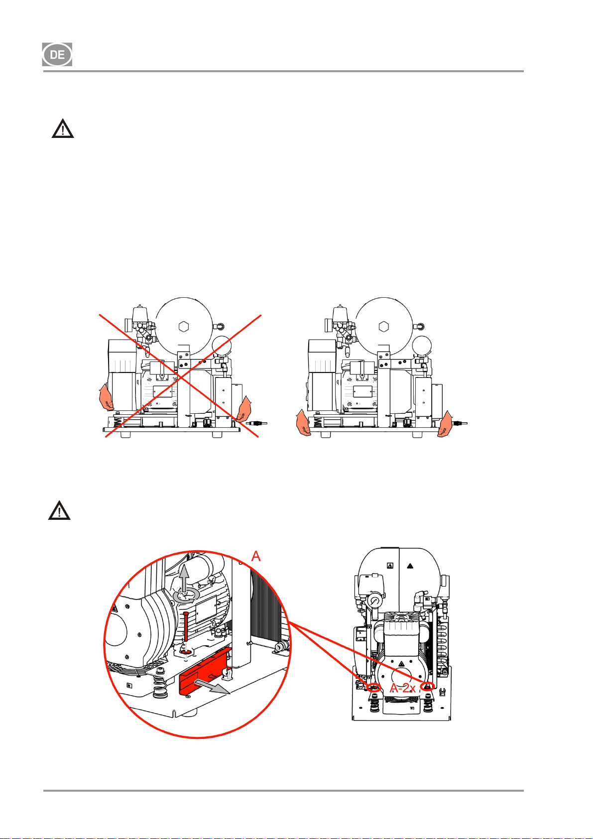
DK50-10
11. AUFSTELLUNG DES KOMPRESSORS
Die Gerätschaft muss von einem qualifizierten Fachmann installiert werden.
Nehmen Sie den Kompressor aus seiner Verpackung.
11.1. Handhabung und Entsichern des Kompressors
Positionieren Sie den Kompressor am künftigen Einsatzort (Abb. 6).
Abb. 6
Entfernen Sie die Transportstützen von den Aggregaten. (Abb. 7)
Entfernen Sie alle für die Sicherung des Kompressors verwendeten Komponenten, nachdem das
Kompressor-Set am endgültigen Einsatzort installiert und montiert wurde!
Fig.7
NP-DK50-1_08-2017-MD - 46 - 08/2017
Page 49
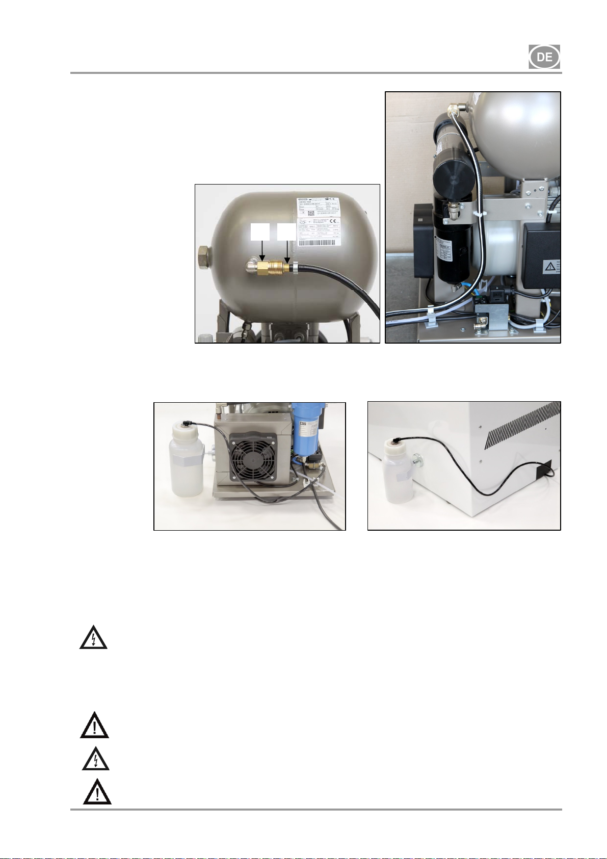
DK50-10
12. PNEUMATISCHE ANSCHLÜSSE
12.1. Druckluftausgang (Abb. 8)
Schließen Sie einen Druckluftschlauch an, der an einem Ende
mit einer Schnellkupplung (1) am Druckluftausgang (2) des
Kompressors angeschlossen wird. Schließen Sie den Schlauch
an das Druckluftsystem oder direkt an die Gerätschaft an, in
diesem Fall an die Dentalausrüstung.
Abb. 8
12.2. Kondensatausgang (Abb. 9)
2 1
Schließen Sie bei Kompressoren mit Trocknern den Kondensatablaufschlauch an den
Kondensatbehälter an.
Abb. 9
Führen Sie bei anderen Kompressoren (ohne Trockner) den Schlauch durch die Öffnung an der
Rückwand des Gehäuses.
13. ELEKTRISCHE ANSCHLÜSSE
Das Produkt wird mit einem Netzkabel mit Schutzkontaktstecker geliefert. Stecken Sie den Netzstecker in
eine Steckdose mit entsprechender Spannung.
Befolgen Sie unbedingt alle lokalen Vorschriften für die Elektrik. Die Netzspannung und
Netzfrequenz müssen mit den Angaben auf dem Gerätetypenschild übereinstimmen.
Die Steckdose muss aus Sicherheitsgründen gut zugänglich sein, damit das Gerät im Notfall schnell
vom Netz getrennt werden kann.
Der Stromkreis darf im Sicherungskasten mit maximal 16 A abgesichert werden.
Das Gehäuse für das DK50-10S/M-Kompressormodell mit 10 bar ist mit einem Kühllüfter und
einem Schalter ausgestattet. Das Gehäuse muss mithilfe des mitgelieferten Kabels mit Stecker
in den passenden Anschluss am Bedienfeld des Kompressors angeschlossen werden. (Abb. 4)
Stellen Sie sicher, dass das Stromkabel keine heißen Komponenten des Kompressors
berührt. Achtung, Stromschlaggefahr!
Beschädigte elektrische Kabel oder Luftschläuche müssen sofort ausgetauscht werden.
08/2017 - 47 - NP-DK50-1_08-2017-MD
Page 50
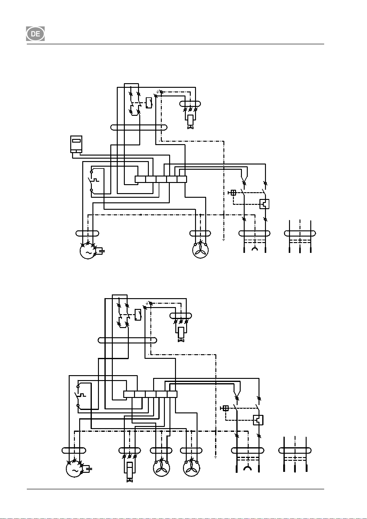
DK50-10
14. ANSCHLUSSPLAN
DK50-10 Z, DK50-10 S 5-7 bar, 6-8 bar, 8-10 bar
1/N/PE ~ 115V / 60 Hz
~ 230V / 50/60 Hz
00000
bk bu
P1*
bk
B2
5G1
bn gy
40°C
bk
3G1
1
bk-1bk-2
M
C1
M1
DK50-10 Z/M, DK50-10 S/M 5-7bar, 6-8 bar
1/N/PE ~ 115V / 60 Hz
~ 230V / 50/60 Hz
5G1
bn gy
bk
bk
B2
X1
40°C
bk
NP-DK50-1_08-2017-MD - 48 - 08/2017
3G1
M
1
M1
bk-1bk-2
bn
3G0,75
C1
B1
p >
bk
2
1
X1
B1
p >
bu
2
1
T
U
bu bu
3G0,5
M4
bn
bu
3G0,75
bu
M3
* - only for 8-10bar version
bu bk
F1
3G1,5
bu
P2
8
gnye
CE
PE
P1
4
gnye
bn
UN
bu bn
3G1,5
PE
UN
UK
U
3G0,75
N
N
gnye
bu bu
bn
3G0,5
E1
bn
bu
M3
bu bk
F1
3G1,5
bu
bu
CE
P2
8
gnye
PE
P1
4
gnye
bn
UN
bu bn
3G1,5
PE
UN
UK
N
N
gnye
bu
E2
bn
3G0,5
E1
bn
Page 51
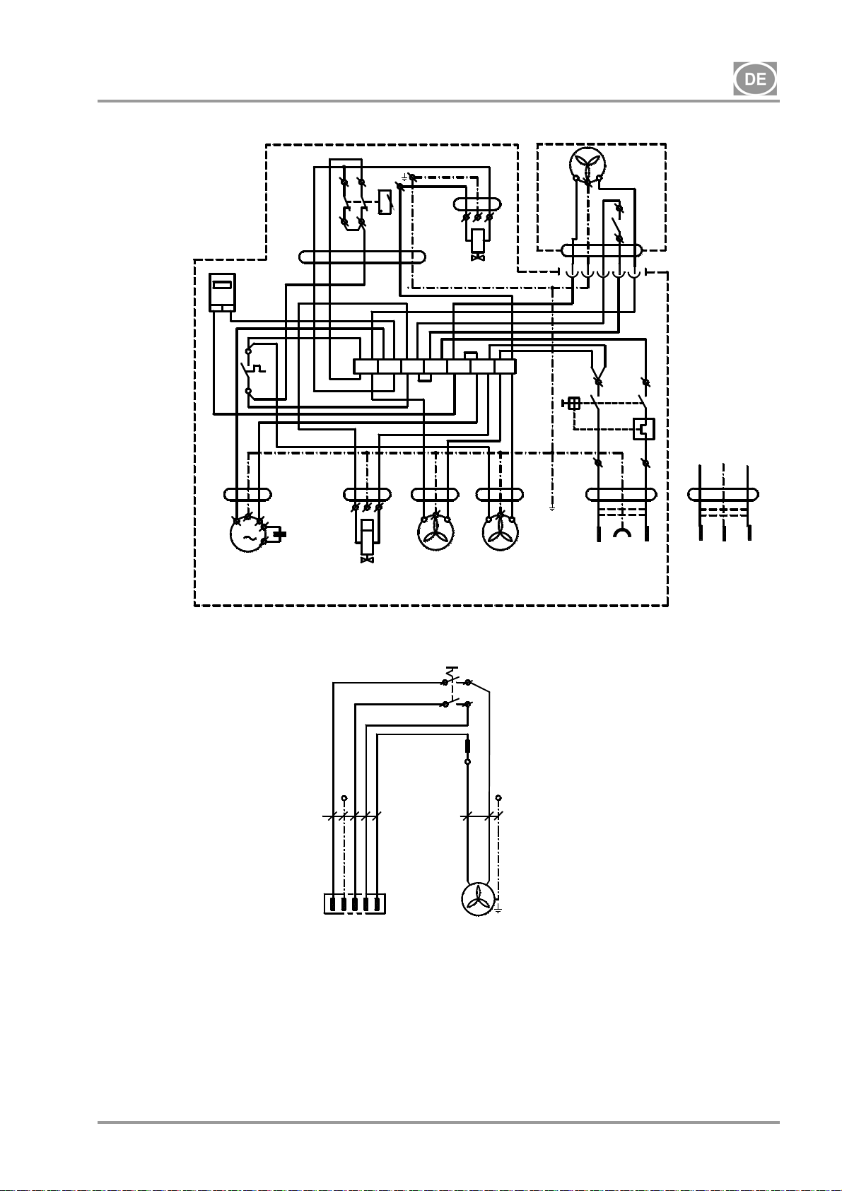
DK50-10
DK50-10 Z/M, DK50-10 S/M 8-10 bar
1/N/PE ~ 230V 50..60Hz
Box für - DK50-10 S/M 10bar
Legende für Elektroschaltpläne
~ 115V 60Hz
bn gy
5G1
00000
P1
bkbu
bk
3G1
B2
40°C
bk
bk-1bk-2
M
1
X1
3G0,75
C1
M1
* - only for DK50-10 Z/M version
1/N/PE ~ 230V 50..60Hz
bu
PE
5G1
-X10
N23PE
M1 Kompressormotor
E1 Kompressorlüfter
E2 Trocknerlüfter
M3 Magnetventil
B2 Temperaturschalter
E3, E10 Gehäuselüfter
X10, X2 Stecker
bn
bn
B1
p >
3G0,75
bk
bu
2
1
U
U
bn
bu
M3
N
N
N
*
gnye
bu bu bu
T
bk
gy
1
M4
bn
3G0,5
-S10
bu
bn
3G0,5
E1
bu
PE
2a
1a
E2
2
1
1
bn
3G0.5
-E10
C1 Kondensator
B1 Druckschalter
X1 Anschlussleiste
F1 Schutzschalter
M4 Kondensatablassventil
P1 Stundenzähler
S1 Schalter
2
E3
S1
bu
gy
bk
5G1
N
bu
F1
bn
1
bk
bk
bu bk
bu
P2
8
gnye
3G1,5
PE
32
bk
X2
P1
4
bn
UN
bu bn
3G1,5
CE UK
1
1 - Compessor
1-Kompressor
2 - Box
2- Gehäuse
gnye
PE
UN
08/2017 - 49 - NP-DK50-1_08-2017-MD
Page 52
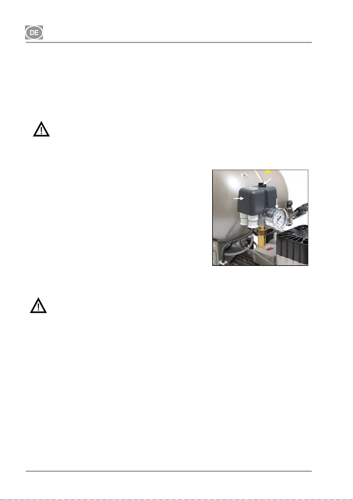
DK50-10
15. INBETRIEBNAHME
(Abb. 10)
Stellen Sie sicher, dass alle Transporthilfen entfernt wurden.
Kontrollieren Sie den ordnungsgemäßen Anschluss aller Druckluftleitungen.
Kontrollieren Sie, ob der Kompressor korrekt an das Stromnetz angeschlossen ist.
Kontrollieren Sie die Position des Hauptschalters; er sollte auf der „I“-Position stehen. Bleibt der Schalter
auf der „0“-Position, stellen Sie den Hauptschalter auf die „I“-Position. (Abb. 3)
Kontrollieren Sie, ob das DK50-10S/M-Gehäuse (nur Modelle mit 810 bar) mithilfe des Steckerkabels mit
dem Kompressor verbunden ist.
Der Kompressor besitzt keine Reserveenergiequelle.
16. EINSCHALTEN DES KOMPRESSORS
(Abb. 10)
Schalten Sie den Kompressor am Druckschalter (2) ein, indem Sie
den Hauptschalter (3) auf die „I“-Position drehen. Überprüfen Sie
die Position des Trennschalters, dieser muss auf der „I“-Position
stehen. Steht dieser auf der „0“-Position, drehen Sie den Schalter
auf die „I“-Position (Abb. 3 – Position 18). Der Schalter (Abb. 4 –
2
Position 22) bei DK50-10S/M-Kompressoren mit 10 bar befindet
sich an der Vorderseite des Gehäuses; die Anzeige leuchtet grün.
Der Kompressor schaltet ein und beginnt, den Druckluftbehälter zu
füllen, bis der Druck den Schaltdruck erreicht und der
Druckschalter den Kompressor ausschaltet. Der Kompressor läuft
anschließend im Automatikmodus und wird durch die Ein- und
Aus-Druckeinstellungen am Druckschalter basierend auf dem
Druckluftverbrauch gesteuert. Dieser Druck kann am Druckmesser
(5) überwacht werden. Eine Toleranz von 10 % ist akzeptabel.
Der Druck im Luftbehälter darf den zulässigen Betriebsdruck nicht
Abb. 10
überschreiten.
Anpassungen an den Druckbereich des Kompressor-Druckschalters sind unzulässig.
Der Druckschalter (2) wurde vom Hersteller eingestellt und diese Einstellungen dürfen
nur von einem vom Hersteller geschulten, qualifizierten Techniker geändert werden.
Kompressor – bei der ersten Betriebsnahme füllt der Kompressor den Druckluftbehälter bis zum
Schaltdruck und der Druckschalter schaltet den Kompressor aus. Der Kompressor läuft im Automatikmodus
und wird durch die Ein- und Aus-Druckeinstellungen am Druckschalter basierend auf dem
Druckluftverbrauch gesteuert.
3
5
Kompressor mit Trockner – der Kompressor läuft auf dieselbe Art und Weise wie oben, nur strömt die
Druckluft durch einen Kühler, um Feuchtigkeit aus der Druckluft zu entfernen.
Kompressor mit Kondensat- und Filtrierungseinheit (KJF-1) – während der Nutzung durch das Gerät
strömt die Druckluft durch die KJF-1-Einheit, wo die Luft gekühlt, gefiltert und das Kondensatwasser erfasst
und automatisch in einen Behälter abgeleitet wird.
17. ABSCHALTEN DES KOMPRESSORS
Das Abschalten des Kompressors für Wartungsarbeiten oder aus anderen Gründen erfolgt über den
Druckschalter (2), indem der Wahlschalter (3) auf die „0“-Position gestellt und der Netzstecker aus der
Steckdose gezogen wird. Damit wird der Kompressor von der Stromversorgung getrennt. Öffnen Sie
anschließend das Ablassventil (Abb. 1), um den Druck im Drucklufttank komplett abzulassen.
NP-DK50-1_08-2017-MD - 50 - 08/2017
Page 53
DK50-10
WARTUNG
18. GERÄTEWARTUNG
Warnung!
Der Bediener muss mindestens alle 24 Monate (EN62353) oder in Intervallen, die durch geltende
nationale Rechtsvorschriften vorgegeben sind, das Gerät regelmäßig testen. Die Testergebnisse
sind aufzuzeichnen (z. B. gemäß EN 62353, Anhang G), darin sind auch die Messverfahren zu
nennen.
Das Gerät wurde so konstruiert und hergestellt, dass nur eine minimale Wartung nötig ist. Die folgenden
Arbeiten sind auszuführen, um eine korrekte und zuverlässige Funktion des Kompressors zu gewährleisten.
Bevor Sie mit den Wartungsarbeiten am Kompressor beginnen, stellen Sie sicher, dass
der Kompressor vom Gerät getrennt ist, um die Person, die am Gerät arbeitet, nicht zu
gefährden und um andere Sachschäden zu vermeiden!
Aggregatkomponenten (Köpfe, Zylinder, Druckschlauch usw.) sind während und direkt
nach dem Kompressorbetrieb sehr heiß – Komponenten nicht berühren!
Tätigkeiten, die den Rahmen der normalen Wartung überschreiten, dürfen nur durch
qualifizierte Fachleute ausgeführt werden.
Dabei dürfen nur vom Hersteller freigegebene Ersatzteile und freigegebenes Zubehör
verwendet werden.
Tragen Sie einen Augenschutz (z. B. eine Schutzbrille), wenn Sie Druckluft aus dem
Druckluftkreislauf (Drucklufttank) ablassen.
Die nachfolgenden Arbeiten dürfen nur von geschultem Personal wie folgt ausgeführt werden:
BEVOR SIE MIT WARTUNGSARBEITEN BEGINNEN, MÜSSEN SIE den Kompressor
abschalten. Trennen Sie anschließend den Kompressor von der Stromversorgung (ziehen
Sie den Hauptstecker), lassen Sie dann die Druckluft aus dem Drucklufttank ab.
Das Kompressormodell mit 10 bar ist mit einem Stundenzähler (Abb. 4) ausgestattet, der die
Betriebsstunden erfasst.
08/2017 - 51 - NP-DK50-1_08-2017-MD
Page 54
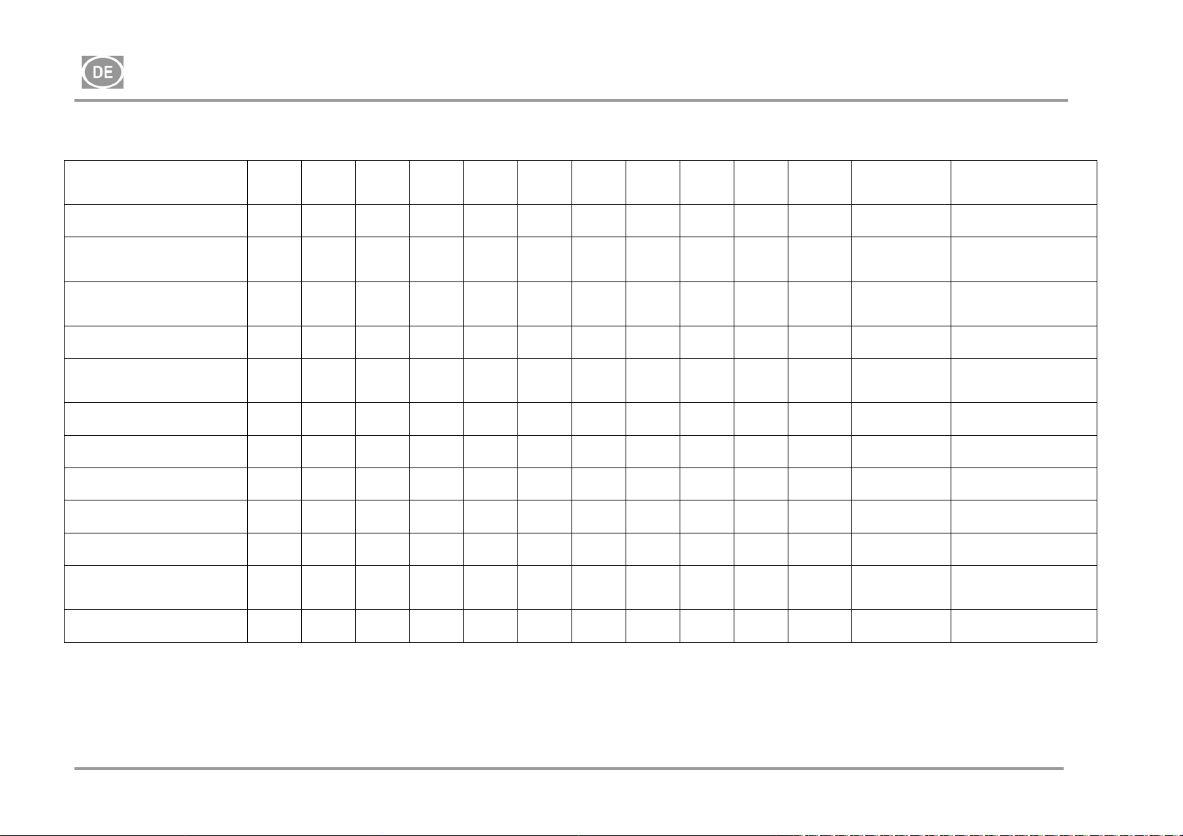
DK50-10
18.1. Wartungsintervalle
Zeitintervall
Betriebliche
Produktüberprüfungen
Kondensat aus
Druckluftbehälter ablassen )**
- Bei hoher Feuchtigkeit
Kondensat aus
Druckluftbehälter ablassen )**
- Bei normaler Feuchtigkeit
Produktfunktionsprüfung x
einmal
täglich
einmal
wöche
ntlich
x 18.2 -
x
x
einmal
jährlich
Alle 2
Jahre
2000 4000 6000 8000 10000 12000 Kapitel Ersatzteil-Set Ausgeführt durch
Benutzer
18.5 - Benutzer
18.5 - Benutzer
7 - Benutzer
Dichtigkeitsprüfung der
Anschlüsse und
Geräteprüfung
Überprüfung der
Stromanschlüsse
Überprüfung von Kühler und
Lüfter
Austausch des Filterelements
im Trocknerfilter
Austausch des Filterelements
im KJF-1
Kontrolle des
Sicherheitsventils
Durchführung einer
„Wiederholungsprüfung“ nach
EN 62353
Austausch AggregatAnsaugfilter )*
x
x
x
x
x
x
x 18 -
x x
18.6 -
x x 18.7 025200126-000
)* Daten werden in Stunden angegeben; falls nicht möglich, werden die Daten in Jahren angegeben
)** nur für Kompressoren ohne Trockner
18.3 -
18.4 -
18.10 -
18.8 025200304-000
18.9 025200061-000
qualifizierte
Fachkraft
qualifizierte
Fachkraft
qualifizierte
Fachkraft
qualifizierte
Fachkraft
qualifizierte
Fachkraft
qualifizierte
Fachkraft
qualifizierte
Fachkraft
qualifizierte
Fachkraft
NP-DK50-1_08-2017-MD - 52 - 08/2017
Page 55
DK50-10
18.2. Betriebsprüfungen
Aggregatzustand prüfen – die Aggregate sollten normal, ohne übermäßige Schwingung oder
Geräuschentwicklung laufen. Beheben Sie jegliche Probleme oder rufen Sie einen Servicemitarbeiter,
falls ein Fehler erkannt wurde
Sichtprüfung des Lüfterbetriebs – die Lüfter müssen anlaufen, wenn ein Aggregat in Betrieb ist.
Beheben Sie jegliche Probleme oder rufen Sie einen Servicemitarbeiter, falls ein Fehler erkannt wurde
Stellen Sie sicher, dass das Netzkabel und die Druckluftschläuche unbeschädigt sind. Ersetzen Sie
beschädigte Komponenten oder rufen Sie einen Servicemitarbeiter.
Überprüfen Sie die Umgebungstemperatur – die Umgebungstemperatur muss unter dem
Temperaturlimit (40 °C) liegen. Kühlen Sie die Umgebung, wenn die Temperatur zu hoch ist.
Bei Kompressoren mit Trockner – öffnen Sie den Stopfen am Kondensatbehälter, um das Kondensat
abzulassen.
18.3. Dichtigkeitsprüfung der Druckluftanschlüsse und Geräteprüfung
Dichtigkeitsprüfung:
Überprüfen Sie die Druckluftleitungen auf Dichtigkeit bei laufendem Kompressor unter Druck (nicht
während der Aufbereitungsentlüftung).
Verwenden Sie ein Lecksuchgerät oder Seifenwasser, um alle Verbindungen und Anschlüsse auf
Undichtigkeiten zu überprüfen. Verbindungen, an denen Undichtigkeiten festgestellt wurden, sind
festzuziehen oder erneut abzudichten.
Geräteinspektion:
Überprüfen Sie den Zustand des Kompressoraggregats auf reibungslosen Betrieb und Geräuschpegel.
Überprüfung der Lüfterfunktion – die Lüfter müssen während der definierten Arbeitszyklen des
Kompressors laufen
Überprüfung der Temperaturschaltung (B2) – heizen Sie den Temperaturschalter auf eine Temperatur
über 40 °C auf (z. B. durch Nutzung einer Wärmepistole. Achten Sie darauf, keine Plastikteile in der
Umgebung zu verformen). Der Lüfter EV1 (und EV2 bei Kompressoren mit Trockner) läuft an, sobald
die Temperatur 40 °C erreicht, sofern der Kompressor an den Strom angeschlossen ist.
Überprüfen Sie den Filterzustand – die Filter müssen unbeschädigt und ausreichend sauber sein.
Überprüfen Sie den Zustand des Aggregats selbst und achten Sie darauf, dass weder
Verschmutzungen im Kurbelwellengehäuse noch Spiel im Kurbelwellengehäuse bestehen.
Defekte Teile sind auszutauschen.
18.4. Überprüfung der Stromanschlüsse
Kontrollieren Sie alle Stromanschlüsse am Gerät bei getrenntem Netzstromanschluss!
Überprüfung
Kontrollieren Sie die mechanische Funktion des Druckschalters.
Stellen Sie sicher, dass das Netzkabel und die angeschlossenen Kabel unbeschädigt sind.
Machen Sie eine Sichtprüfung der Anschlüsse der einzelnen Kabel an der Klemmleiste.
Überprüfen Sie bei allen Schraubklemmen die schützenden grünen und gelben PE-Erdungsleiter.
08/2017 - 53 - NP-DK50-1_08-2017-MD
Page 56
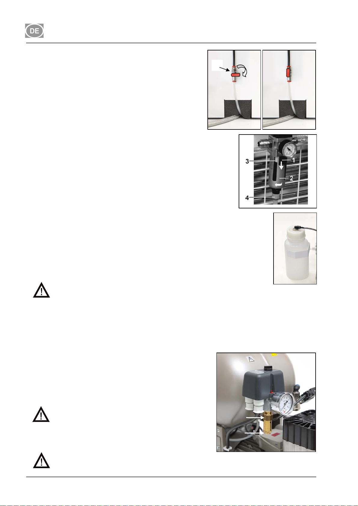
A
DK50-10
18.5. Kondensatablassventil
Kompressoren (Abb. 11)
1
Es wird empfohlen, das Kondensat aus dem Druckbehälter
während des normalen Betriebs abzulassen. Schalten Sie den
Kompressor am Netzschalter ab und senken Sie den Druck auf
max. 1 bar, z. B. durch Entlüften durch das angeschlossene
Gerät. Setzen Sie den Schlauch mit dem Ablassventil in einen
bereitstehenden Behälter und öffnen Sie das Ablassventil (1),
um Kondensat aus dem Behälter ablaufen zu lassen.
bb. 11
Kompressoren mit Kondensations- und Filtrationseinheit
(Abb.12)
Während des regulären Betriebs des Kompressors wird das
entstehende Kondensat automatisch über das Auslassventil des
Filters der Kondensationseinheit abgeschieden. Um die korrekte
Funktion des automatischen Ablaufs zu überprüfen, öffnen Sie
das Ventil (4) des Ablaufbehälters (2) durch Drehen nach rechts.
Lassen Sie eine kleine Menge Kondensat aus dem Behälter
laufen. Schließen Sie das Ventil (4) durch Drehen nach rechts.
Abb. 12
Beide Kompressormodelle können mit einem automatischen
Kondensatablauf am Kondensatablauf des Druckluftbehälters
ausgestattet werden, damit das Kondensat ohne
Bedienereingriff ablaufen kann (siehe Lieferumfang – Kapitel
Zubehör).
Kompressoren mit Lufttrockner (Abb. 13)
Das Kondensat aus Kompressoren mit Lufttrocknern wird
automatisch in einen Behälter abgeleitet. Der Behälter muss
regelmäßig entleert werden, siehe Kapitel 18.2
Abb. 13
FOLGENDE SCHRITTE SIND VOR ALLEN WEITEREN KONTROLLEN ERFORDERLICH:
Bei DK50-10S- und DK50-10S/M-Kompressoren mit einem Gehäuse – Gehäuse entfernen/abheben.
Bei dem DK50-10S/M-Kompressormodell mit 10 bar mit Gehäuse – entfernen Sie die Abdeckung des
Gehäuses, trennen Sie die Gehäuseverbindung vom Kompressoranschluss und entfernen/heben Sie
das Gehäuse ab.
18.6. Kontrolle des Sicherheitsventils
(Abb. 14)
Wenn der Kompressor erstmals in Betrieb genommen wird,
stellen Sie sicher, dass das Sicherheitsventil korrekt funktioniert.
Drehen Sie die Schraube (2) des Sicherheitsventils (1) mehrere
Umdrehungen nach links, bis das Sicherheitsventil Luft ablässt.
Das Sicherheitsventil nur kurz frei ausblasen lassen. Die
Schraube (2) nach rechts bis zum Anschlag drehen. Das Ventil
muss jetzt wieder geschlossen sein.
Verwenden Sie das Sicherheitsventil niemals, um
Druckluft aus dem Druckluftbehälter abzulassen.
Dadurch könnte das Sicherheitsventil beschädigt
werden. Das Ventil ist durch den Hersteller auf den
maximal zulässigen Druck voreingestellt.
1
2
Justierungen sind nicht zulässig!
Abb.14
Warnung! Druckluft kann gefährlich sein. Tragen Sie beim Ablassen einen Augenschutz.
Druckluft kann die Augen schädigen oder zu Sehproblemen führen.
NP-DK50-1_08-2017-MD - 54 - 08/2017
Page 57
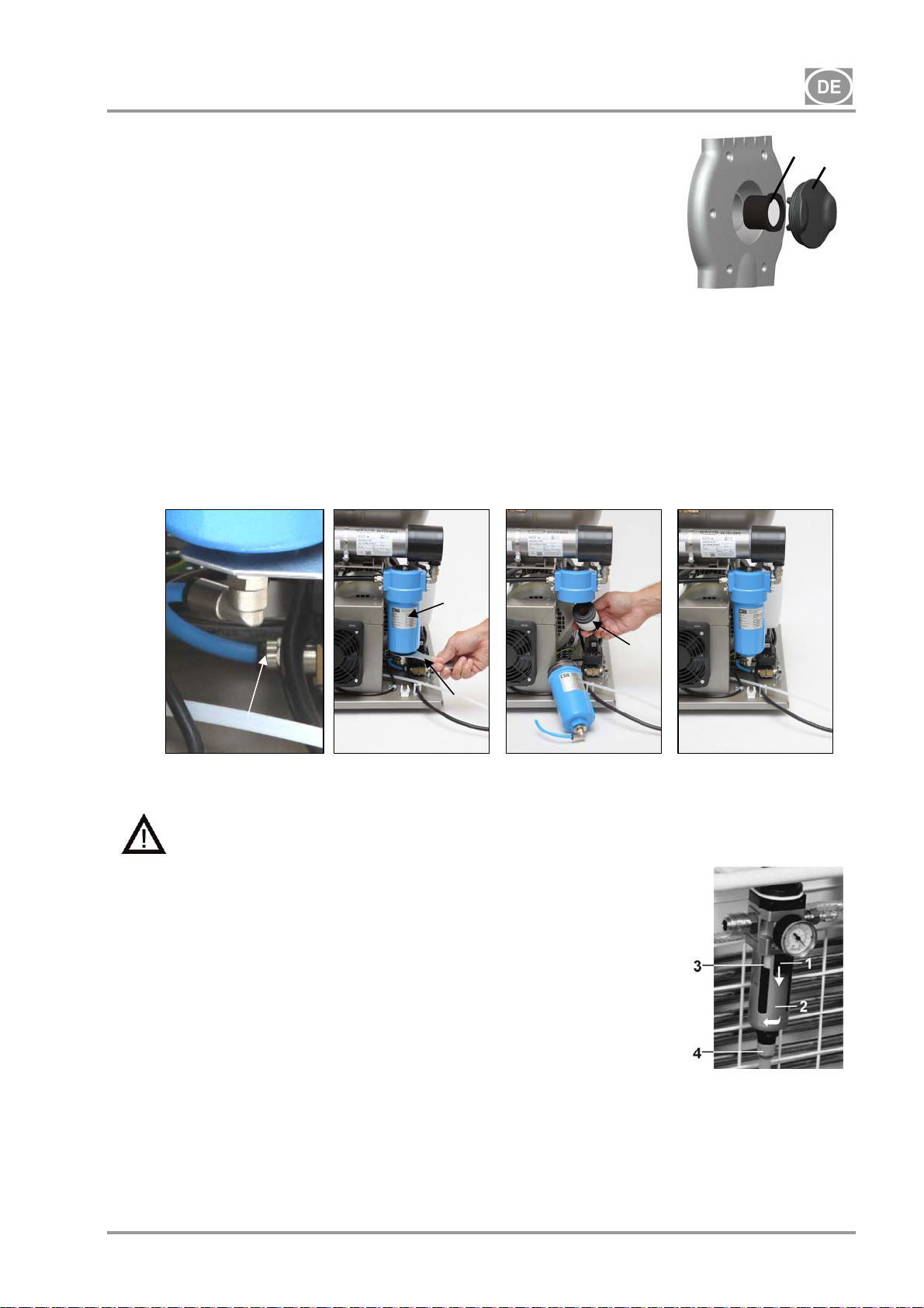
DK50-10
18.7. Austausch des Ansaugfilters
(Abb.15)
Ziehen Sie den Gummistopfen (2) mit der Hand heraus.
Entfernen Sie den verschmutzten Ansaugfilter (1).
Setzen Sie einen neuen Filter ein und setzen Sie den Gummistopfen wieder
ein.
18.8. Austausch des Filterelements
Abb.15
(Abb.16)
Entfernen Sie den Schlauch (1) von der Schnellkupplung.
Verwenden Sie einen Schraubenschlüssel (2), um den Filterbehälter (3) zu lösen und entfernen Sie
diesen.
Ziehen Sie das Filterelement (3) zum Entfernen nach unten.
Setzen Sie ein neues Filterelement ein.
Bringen Sie den Filterbehälter wieder an.
Ziehen Sie den Filterbehälter vorsichtig mit dem Schraubenschlüssel fest.
Schließen Sie den Schlauch erneut an die Schnellkupplung an.
Abb. 16
1
3
4
2
18.9. Austausch des Filterelements in der KJF-1-Einheit
Bevor Sie fortfahren, verringern Sie den Luftdruck im Druckluftbehälter auf Null und
trennen Sie das Gerät vom Stromnetz.
(Abb.17)
Ersetzen Sie den Filter im automatischen Kondensatablauf,
wenn die Kondensateinheit im Normalbetrieb ist.
Lösen Sie den Riegel (1) am Filterbehälter durch Ziehen
nach unten, drehen Sie die Filterabdeckung (2) nach links
und entfernen Sie den Filter.
Schrauben Sie die Filterhalterung (3) durch Drehen nach
links ab.
Ersetzen und sichern Sie den neuen Filter durch Drehen der
Filterhalterung nach rechts am Filterkörper.
Setzen Sie die Filterabdeckung zurück und sichern Sie
diese durch Drehen nach rechts, bis die Sicherung einrastet.
Abb. 17
18.10. Überprüfung von Kühler und Lüfter (Abb. 3)
Das gesamte Gerät, vor allem der Kompressorlüfter, Kühlerlüfter (21) und Kühler (14) sind sauber zu halten,
um eine wirkungsvolle Trocknung zu gewährleisten. Saugen oder blasen Sie die Kühlrippen und Lüfter mit
Druckluft ab, um Staub von der Oberfläche zu entfernen.
08/2017 - 55 - NP-DK50-1_08-2017-MD
Page 58
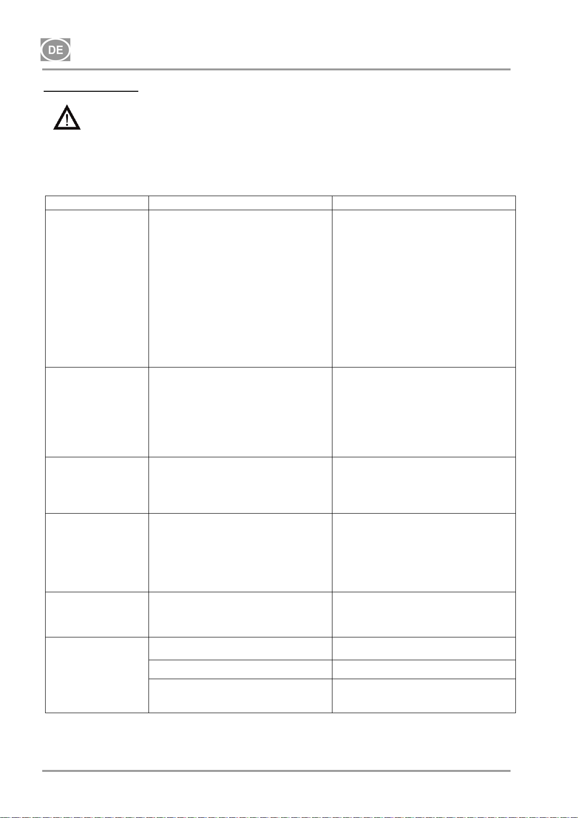
DK50-10
FEHLERBEHEBUNG
Vorsicht! Bevor Sie fortfahren, müssen Sie den Luftdruck im Druckluftbehälter auf Null
verringern und das Gerät vom Stromnetz trennen.
Für eine durchgängig wirkungsvolle Trocknung ist es erforderlich, das gesamte Gerät und in erster
Linie den Ventilator sauber zu halten – reinigen Sie die Oberfläche des Ventilators und der
Kühlrippen des Kühlers regelmäßig.
Die Fehlerbehebung darf nur durch qualifizierte Fachkräfte erfolgen.
STÖRUNGEN MÖGLICHE URSACHE ABHILFE
Kompressor springt
nicht an
Kompressor schaltet
sich oft an
Niedriger Druck im
Druckluftbehälter
(Kompressor läuft
durchgängig)
Betrieb des
Kompressors über
einen längeren
Zeitraum
Kompressor ist laut
(Klopfen,
Metallgeräusche)
Trockner trocknet
nicht (Kondenswasser
in der Luft)*
Keine Spannung am Druckschalter
Störung Motorspule,
Thermischer Überlastungsschutz
Kondensator defekt
Festsitzen des Kolbens oder eines
anderen rotierenden Teils
Der Druckschalter funktioniert nicht
Luftleck im Druckluftverteilungssystem
Undichtigkeit des Rückschlagventils
Größere Menge kondensierter
Flüssigkeit im Druckbehälter
Niedrige Kompressorleistung
Hoher Druckluftverbrauch des Geräts,
Undichtigkeit im Druckluftsystem,
niedrige Geräteleistung
Störung des Aggregats
Störung des Trockners
Luftleck im Druckluftverteilungssystem
Verschlissener Kolbenring
Ansaugfilter ist verstopft
Fehlerhaftes Magnetventil
Schäden an Kolbenlager, Kolbenstange,
Motorlager
Lockeres oder geborstenes
Dämpfelement (Feder)
Kühlerlüfter funktioniert nicht Lüfter austauschen
Beschädigter Trockner Den Trockner austauschen
Überprüfen Sie die Spannungskontrolle
an der Steckdose
Überprüfen Sie den Schutzschalter –
schalten Sie ihn auf die „I“-Position
Lose Klemme an der Klemmleiste –
anziehen
Überprüfen Sie das Stromkabel –
ersetzen Sie defekte Kabel
Motor oder Wicklungen ersetzen
Kondensator wechseln
Beschädigte Teile wechseln
Funktion des Druckschalters kontrollieren
Kontrolle des
Druckluftverteilungssystems – undichte
Verbindungen abdichten
Magnetventil reinigen, Dichtungen
austauschen, Magnetventil austauschen,
kondensierte Flüssigkeit ablassen
Zeit bis zum Auffüllen des
Druckluftbehälters kontrollieren
Kontrolle des
Druckluftverteilungssystems – undichte
Verbindungen abdichten
Verschlissenen Kolbenring ersetzen
Alten Filter durch neuen Filter ersetzen
Ventil oder Spule reparieren oder
wechseln
Beschädigtes Lager ersetzen
Beschädigte Feder auswechseln
Stromquelle kontrollieren
Automatischer Kondensatablauf
funktioniert nicht – Filter
reinigen/austauschen
)* Nach einer Störung des Trockners müssen die Innenflächen des Druckluftbehälters gründlich gereinigt
und die Kondensatflüssigkeit entfernt werden.
NP-DK50-1_08-2017-MD - 56 - 08/2017
Reinigen/Austauschen
Page 59

DK50-10
Prüfen Sie den Taupunkt der Luft, die aus dem Druckluftbehälter entweicht (vgl. Kapitel 5 –
Technische Daten), um das angeschlossene Gerät vor Schäden zu bewahren!
19. INFORMATIONEN ZU REPARATURBETRIEBEN
Garantieleistungen und Reparaturen nach Ablauf der Garantie werden durch den Hersteller, durch vom
Hersteller benannte Firmen oder durch vom Hersteller autorisiertes Servicepersonal sichergestellt.
Der Hersteller behält sich das Recht vor, ohne Vorankündigung Änderungen am Gerät
vorzunehmen. Änderungen beeinträchtigen nicht die Funktionen des Geräts.
20. LAGERUNG
Wenn der Kompressor über einen längeren Zeitraum nicht genutzt wird, lassen Sie das Kondensat
vollständig aus dem Behälter ab. Schalten Sie anschließend den Kompressor 10 Minuten lang ein und
lassen Sie das Ablassventil (1) (Abb. 11) offen. Schalten Sie danach den Kompressor mittels des Schalters
(3) auf dem Druckschalter (2) (Abb. 9) aus, schließen Sie das Ventil für den Kondensatablass und trennen
Sie das Gerät vom Stromnetz.
21. ENTSORGUNG DES GERÄTS
Das Gerät vom Stromnetz trennen.
Druckluft aus dem Druckluftbehälter durch Öffnen des Ablassventils (1) (Abb. 11) ablassen.
Entsorgen Sie das Gerät gemäß den geltenden Umweltvorschriften.
Bitte beauftragen Sie ein Fachunternehmen mit der Abfalltrennung und -entsorgung.
Verschlissene Bauteile haben keine negativen Auswirkungen auf die Umwelt.
08/2017 - 57 - NP-DK50-1_08-2017-MD
Page 60

DK50-10
SOMMAIRE
INFORMATIONS IMPORTANTES ........................................................................................................ 59
1. MARQUAGE CE ....................................................................................................................... 59
2. AVERTISSEMENTS ................................................................................................................. 59
3. AVERTISSEMENTS ET SYMBOLES ....................................................................................... 60
4. STOCKAGE ET TRANSPORT ................................................................................................. 61
5. DONNÉES TECHNIQUES ........................................................................................................ 62
6. DESCRIPTION DU PRODUIT .................................................................................................. 65
7. FONCTIONNALITÉ DU PRODUIT ........................................................................................... 67
8. SCHÉMA PNEUMATIQUE ....................................................................................................... 71
FONCTIONNEMENT ............................................................................................................................. 72
9. MISE SOUS TENSION DU COMPRESSEUR ......................................................................... 72
INSTALLATION ..................................................................................................................................... 73
10.CONDITIONS D’EMPLOI ......................................................................................................... 73
11.POSITIONNEMENT DU COMPRESSEUR .............................................................................. 74
12.RACCORDS PNEUMATIQUES ................................................................................................ 75
13.BRANCHEMENTS ÉLECTRIQUES ......................................................................................... 75
14. SCHÉMA DE BRANCHEMENT ............................................................................................... 76
15.MISE EN SERVICE................................................................................................................... 78
16.MISE SOUS TENSION DU COMPRESSEUR ......................................................................... 78
17.ARRÊT DU COMPRESSEUR .................................................................................................. 78
MAINTENANCE .................................................................................................................................... 79
18.ENTRETIEN DE L’APPAREIL .................................................................................................. 79
DÉPANNAGE ........................................................................................................................................ 84
19.SERVICE DE RÉPARATION .................................................................................................... 85
20.STOCKAGE .............................................................................................................................. 85
21.MISE AU REBUT DE L’APPAREIL ........................................................................................... 85
ANNEXE .............................................................................................................................................. 198
22.REGISTRE D’INSTALLATION ................................................................................................ 200
NP-DK50-1_08-2017-MD - 58 - 08/2017
Page 61

DK50-10
INFORMATIONS IMPORTANTES
1. MARQUAGE CE
Les produits indiqués par la marque de conformité CE répondent aux directives de sécurité de l’Union
européenne (93/42/EEC).
2. AVERTISSEMENTS
Le produit est conçu et fabriqué de sorte à ne présenter aucun danger pour l’utilisateur et son
environnement lorsqu’il est utilisé de la façon prescrite. Gardez les avertissements suivants à l’esprit. Ils
permettent de maintenir les risques à leur occurrence minimale.
2.1. Avertissements généraux
Le manuel de l’utilisateur permet l’installation, l’utilisation et la maintenance appropriées du produit. Il est
fourni avec le produit et doit être tenu à portée de main en tout temps. L’utilisation stricte de ce manuel
vous fournira les informations nécessaires pour une utilisation correcte du produit.
Conservez l’emballage d’origine pour le retour éventuel du produit. Seul l’emballage d’origine garantit la
protection adéquate du produit pendant le transport. S’il est nécessaire de retourner le produit au cours
de la période de garantie, le fabricant n’est nullement responsable des dommages consécutifs à
l’utilisation d’un emballage inapproprié.
La présente garantie ne couvre pas les dommages dus à l’emploi d’accessoires ou de matériaux autres
que ceux indiqués ou recommandés par le fabricant.
Le fabricant garantit uniquement la sécurité, la fiabilité et le fonctionnement du produit, sous réserve
que :
- toutes installations, tous nouveaux réglages, toutes modifications, tout développement et toutes
réparations soient confiés au fabricant ou au prestataire de service autorisé par le fabricant ;
- le produit soit utilisé conformément au manuel de l’utilisateur.
Le présent manuel de l’utilisateur présente, au moment de son impression, la configuration du produit,
ainsi que sa conformité avec les normes techniques et de sécurité applicables. Le fabricant se réserve
tous les droits sur la protection de sa configuration, des méthodes d’installation et des dénominations
utilisées.
La traduction du présent manuel de l’utilisateur est effectuée en conformité avec les meilleures
connaissances disponibles. La version slovaque fait foi en cas d’incertitudes.
2.2. Avertissements généraux de sécurité
Le fabricant a conçu et fabriqué le produit de sorte à minimiser les risques lorsqu’il est utilisé correctement.
Veuillez prendre conscience des mesures de sécurité suivantes afin de réduire les risques résiduels.
L’utilisation et le fonctionnement du produit doivent respecter les codes et règlements locaux en vigueur.
L’opérateur et l’utilisateur sont tenus de respecter tous les règlements pertinents dans l’intérêt de
l’exécution sûre de leurs travaux.
Seule l’utilisation des pièces d’origine peut garantir la sécurité du personnel utilisateur et le
fonctionnement sans faille du produit lui-même. Seuls les accessoires et pièces mentionnés dans la
documentation technique ou explicitement agréés par le fabricant doivent être utilisés.
L’opérateur doit s’assurer que l’équipement fonctionne de façon correcte et sûre avant chaque
utilisation.
L’utilisateur doit parfaitement comprendre le fonctionnement de l’équipement.
N’utilisez pas le produit dans des environnements explosifs.
Dès qu’un problème survient au cours de l’utilisation de l’équipement, l’utilisateur doit immédiatement
en informer le fournisseur.
08/2017 - 59 - NP-DK50-1_08-2017-MD
Page 62
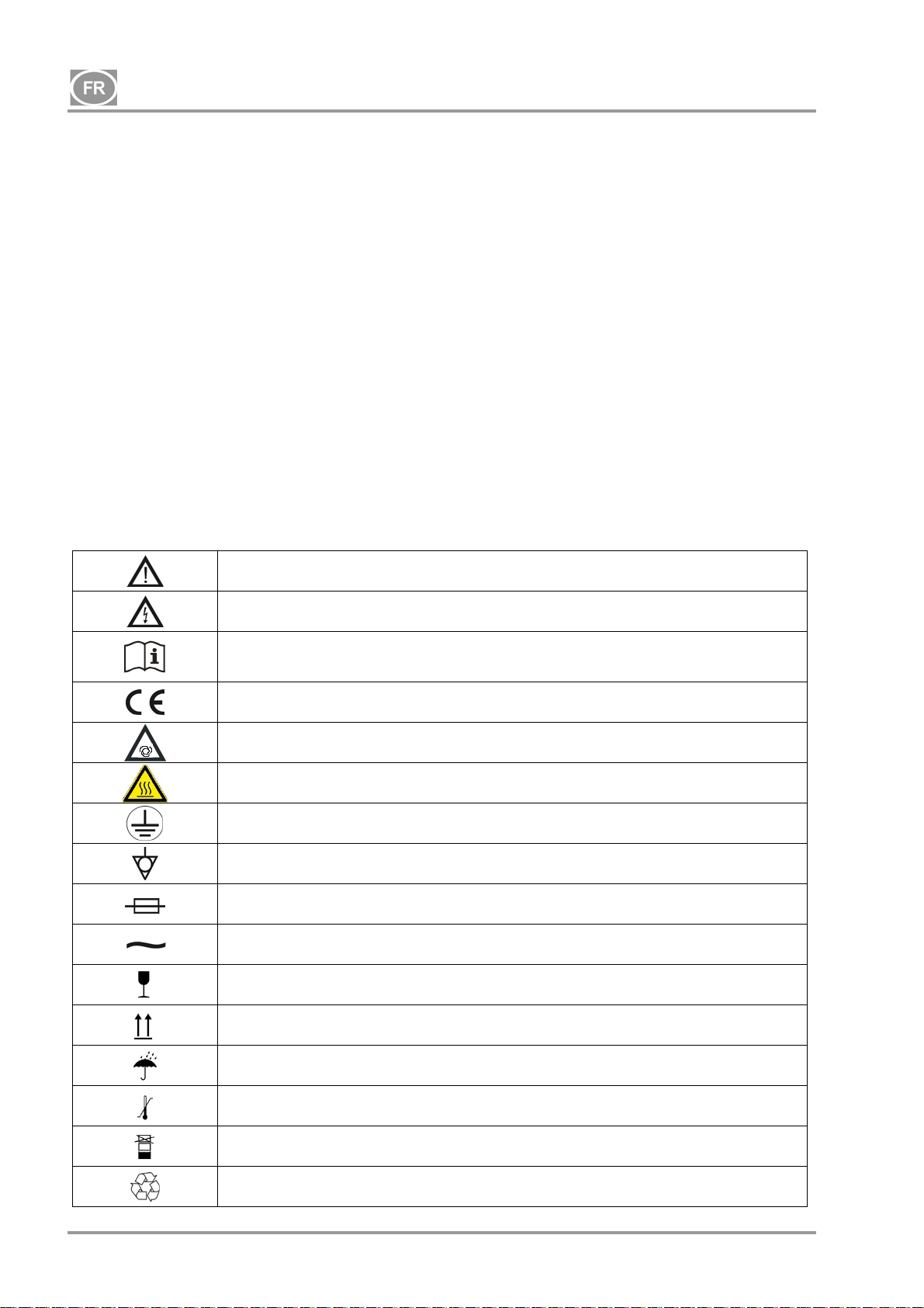
DK50-10
2.3. Avertissements de sécurité liés aux systèmes électriques
L’équipement doit uniquement être branché à une prise correctement installée et mise à la terre.
Avant de brancher le produit, assurez-vous que la tension et la fréquence indiquées sur le produit sont
identiques aux valeurs du réseau électrique.
Vérifiez tout dommage sur le système d’air comprimé connecté et sur le circuit électrique avant
utilisation. Remplacez immédiatement les conducteurs pneumatiques et électriques endommagés.
Débranchez immédiatement le produit du secteur (retirez le cordon d’alimentation de la prise) en
situations dangereuses ou en cas de dysfonctionnement technique.
Assurez-vous de ce qui suit pendant la maintenance et les réparations :
- débranchez le cordon d’alimentation de la prise d’alimentation électrique ;
- dépressurisez les conduites d’air comprimé et du réservoir d’air.
Seul un technicien qualifié peut installer le produit.
3. AVERTISSEMENTS ET SYMBOLES
Les étiquettes et les symboles suivants sont utilisés dans le manuel de l’utilisateur et sur l’équipement et
son emballage pour indiquer les détails et les informations importants :
Informations, instructions et mises en garde à des fins de prévention des lésions
corporelles ou des dégâts matériels.
Mise en garde ! Tension électrique dangereuse
Merci de bien vouloir lire le manuel de l’utilisateur !
Marquage de conformité CE
Mise en garde ! Surface chaude
Le compresseur est commandé à distance et peut se mettre en marche sans
avertissement
Raccordement à la terre
Borne de connexion de mise à la terre
Fusible
Courant alternatif
Marque de manipulation sur l’emballage – FRAGILE
Marque de manipulation sur l’emballage – HAUT
NP-DK50-1_08-2017-MD - 60 - 08/2017
Marque de manipulation sur l’emballage – TENIR AU SEC
Marque de manipulation sur l’emballage – LIMITATIONS DE TEMPÉRATURE
Marque de manipulation sur l’emballage – EMPILEMENT LIMITÉ
Marque sur l’emballage – MATÉRIAU RECYCLABLE
Page 63
DK50-10
4. STOCKAGE ET TRANSPORT
Le compresseur est expédié dans un emballage de transport en carton qui le protège de tout dommage
durant le transport.
Mise en garde ! Pour le transport, utilisez toujours l’emballage d’origine et calez le
compresseur en position verticale.
Pendant le transport et au moment de le ranger, protégez le compresseur contre l’humidité et les
températures extrêmes. Le compresseur dans son emballage d’origine peut être stocké dans un
Conditions ambiantes de stockage et de transport
emplacement chaud, sec et sans poussières. Évitez de le stocker à proximité des produits
chimiques.
Gardez l’emballage, si possible. Dans le cas contraire, veuillez jeter l’emballage de façon
écologique, ou le recycler si possible.
Mise en garde ! Avant de déplacer ou de transporter le compresseur, relâchez toute la
pression d’air du réservoir et des tuyaux et purgez l’eau condensée.
Les produits ne peuvent être stockés et transportés que dans des véhicules exempts de toute trace de
produits chimiques volatils dans les conditions suivantes :
Température : - 25 °C à + 55 °C, 24 h à jusqu’à + 70 °C
Humidité relative : 10 % à 90 % (sans condensation)
08/2017 - 61 - NP-DK50-1_08-2017-MD
Page 64
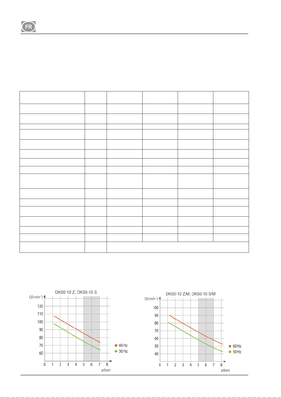
DK50-10
5. DONNÉES TECHNIQUES
Les compresseurs sont conçus pour des environnements intérieurs secs et ventilés présentant les
conditions suivantes :
Température : + 5 °C à + 40 °C
Humidité relative maximale : 70 %
Humidité absolue maximale : 15 g/m
Tab. 1
3
5 – 7 bar
Tension nominale / Fréquence
(*)
Puissance de sortie
5 bar
Pression de travail (**) bar 5,0 – 7,0 5,0 – 7,0 5,0 – 7,0 5,0 – 7,0
Puissance de sortie avec KJF-1
5 bar
Courant maximal A
Puissance de sortie du moteur kW 0,55 0,55 0,55 0,55
Volume du réservoir d’air Lit. 10 10 10 10
Qualité de l’air – filtrage
Pression maximale de
fonctionnement de la soupape
de sûreté
Niveau de bruit à 5 bar LpfA [dB]
Mode de fonctionnement 100 % - S 1 100 % - S 1 100 % - S 1 100 % - S 1
Performance de séchage PDP à
7 bar
Temps de remplissage du
réservoir d’air de 0 à 6 bar
Dimensions (nettes) l. x P. x H. mm 485 x 350 x 553 580 x 440 x 655 544 x 350 x 553 649 x 440 x 655
Poids net kg
Configuration selon
EN 60601-1
V / Hz
Lit. min-1
Lit. min-1
m
bar 8,0 8,0 8,0 8,0
- -
s
Type B, Classe I.
DK50-10 Z DK50-10 S DK50-10 Z/M
230 / 50 / 60
115 / 60
75 / 85
85
75 / 85
85
3,8 / 4,8
9.5
- - 0,3 0,3
65 / 66,5
66,5
50 / 44
44
***) 53 (***)
38 (
230 / 50 / 60
115 / 60
75 / 85
85
75 / 85
85
3,8 / 4,8
9.5
49,5 / 51
51
50 / 44
44
230 / 50 / 60
115 / 60
58 / 68
68
- -
4,1 / 5,1
10
67 / 68,5
68,5
+3 °C
70 / 60
60
44
DK50-10 S/M
230 / 50 / 60
115 / 60
58 / 68
68
4,1 / 5,1
10
51,5 / 53
53
+3 °C
70 / 60
60
61
Remarques :
(*) Lors de la commande, indiquez la version du compresseur
(**) Plage de pression : consultez le fournisseur
(***) Poids des compresseurs avec une unité KJF1 : ajoutez 3 kg
(****) La pression de fonctionnement autorisée de la soupape de sécurité peut également être définie à une
autre valeur, à 9 Bars, par exemple. Le réglage doit être spécifié dans la commande.
NP-DK50-1_08-2017-MD - 62 - 08/2017
Page 65
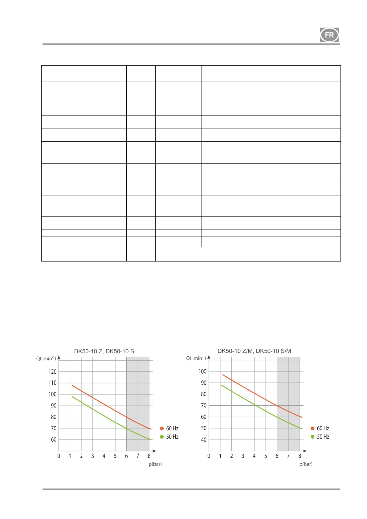
DK50-10
Tab. 2
6 – 8 bar
Tension nominale / Fréquence
(*)
Puissance de sortie
6 bar
Pression de travail (**) bar 6,0 – 8,0 6,0 – 8,0 6,0 – 8,0 6,0 – 8,0
Puissance de sortie avec KJF-1
6 bar
Courant maximal A
Puissance de sortie du moteur kW 0,55 0,55 0,55 0,55
Volume du réservoir d’air 10 10 10 10
Qualité de l’air – filtrage
Pression maximale de
fonctionnement de la soupape
de sûreté
Niveau de bruit à 5 bar LpfA [dB]
Mode de fonctionnement
Performance de séchage PDP à
7 bar
Temps de remplissage du
réservoir d’air de 0 à 7 bar
Dimensions (nettes) l. x P. x H. mm 485 x 350 x 553 580 x 440 x 655 544 x 350 x 553 649 x 440 x 655
Poids net kg
Configuration selon
EN 60601-1
V / Hz
Lit. min-1
Lit. min-1
m
bar 12,0 12,0 12,0 12,0
- -
s
DK50-10 Z DK50-10 S DK50-10 Z/M
230 / 50 / 60
115 / 60
70 / 80
80
70 / 80
80
3,9 / 4,9
9,8
- - 0,3 0,3
65 / 66,5
66,5
100 % - S 1 100 % - S 1 100 % - S 1 100 % - S 1
60 / 51
51
38 (
***) 53 (***)
230 / 50 / 60
115 / 60
70 / 80
80
70 / 80
80
3,9 / 4,9
9,8
49,5 / 51
51
60 / 51
51
Type B, Classe I.
230 / 50 / 60
115 / 60
60 / 70
70
- -
4,1 / 5,1
10,2
67 / 68,5
68,5
+3 °C
72 / 61
61
44
DK50-10 S/M
230 / 50 / 60
115 / 60
60 / 70
70
4,1 / 5,1
10,2
51,5 / 53
53
+3 °C
72 / 61
61
61
Remarques :
(*) Lors de la commande, indiquez la version du compresseur
(**) Plage de pression : consultez le fournisseur
(***) Poids des compresseurs avec une unité KJF1 : ajoutez 3 kg
(****) La pression de fonctionnement autorisée de la soupape de sécurité peut également être définie à une
autre valeur, à 9 Bars, par exemple. Le réglage doit être spécifié dans la commande.
08/2017 - 63 - NP-DK50-1_08-2017-MD
Page 66
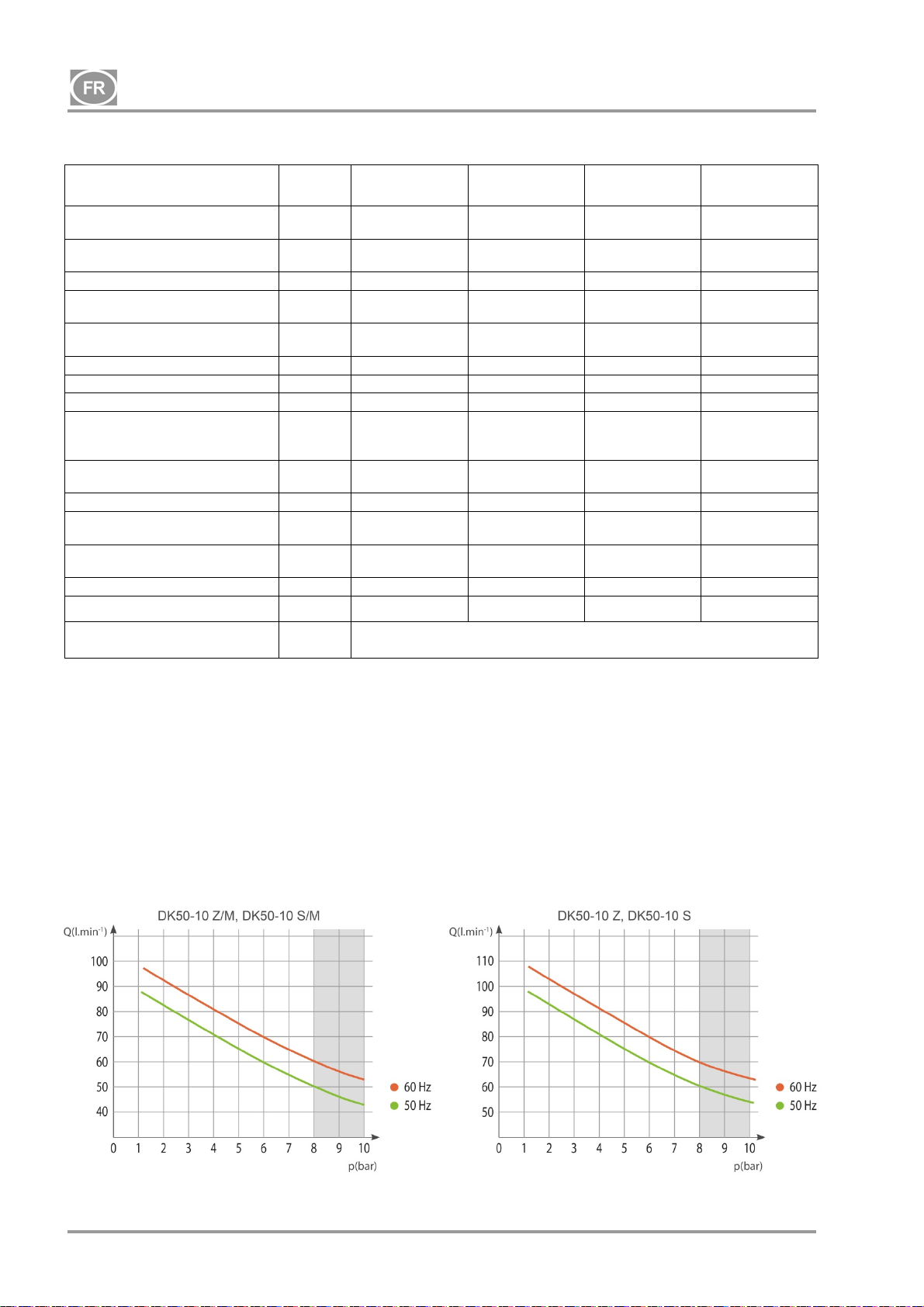
DK50-10
Tab. 3
8 – 10 bar
Tension nominale / Fréquence
(*)
Puissance de sortie
8 bar
Pression de travail (**) bar 8,0 – 10,0 8,0 – 10,0 8,0 – 10,0 8,0 – 10,0
Puissance de sortie avec KJF-1
8 bar
Courant maximal A
Puissance de sortie du moteur kW 0,55 0,55 0,55 0,55
Volume du réservoir d’air 10 10 10 10
Qualité de l’air – filtrage
Pression maximale de
fonctionnement de la soupape
de sûreté
Niveau de bruit à 5 bar LpfA [dB]
Mode de fonctionnement
Performance de séchage PDP à
7 bar
Temps de remplissage du
réservoir d’air de 0 à 9 bar
Dimensions (nettes) l. x P. x H mm 485 x 350 x 553 580 x 440 x 655 544 x 350 x 553 649 x 440 x 655
Poids net kg
Configuration selon
EN 60601-1
V / Hz
Lit. min-1
Lit. min-1
m
bar 12,0 12,0 12,0 12,0
- -
s
DK50-10 Z DK50-10 S DK50-10 Z/M
230 / 50 / 60
115 / 60
60 / 70
70
60 / 70
70
4,1 / 5,1
10,2
- - 0,3 0,3
65 / 66,5
66,5
100 % - S 1 100 % - S 1 100 % - S 1 100 % - S 1
85 / 75
75
38 (
***) 53 (***)
230 / 50 / 60
115 / 60
60 / 70
70
60 / 70
70
4,1 / 5,1
10,2
49,5 / 51
51
85 / 75
75
Type B, Classe I.
230 / 50 / 60
115 / 60
50 / 60
60
- -
4. / 5,3
10,5
67 / 68,5
68,5
+3 °C
96 / 82
82
44
DK50-10 S/M
230 / 50 / 60
115 / 60
50 / 60
60
4,4 / 5,4
10,5
51,5 / 53
53
+3 °C
96 / 82
82
61
Remarques :
(*) Lors de la commande, indiquez la version du compresseur
(**) Plage de pression : consultez le fournisseur
(***) Poids des compresseurs avec une unité KJF1 : ajoutez 3 kg
(****) La pression de fonctionnement autorisée de la soupape de sécurité peut également être définie à une
autre valeur, à 9 Bars, par exemple. Le réglage doit être spécifié dans la commande.
NP-DK50-1_08-2017-MD - 64 - 08/2017
Page 67
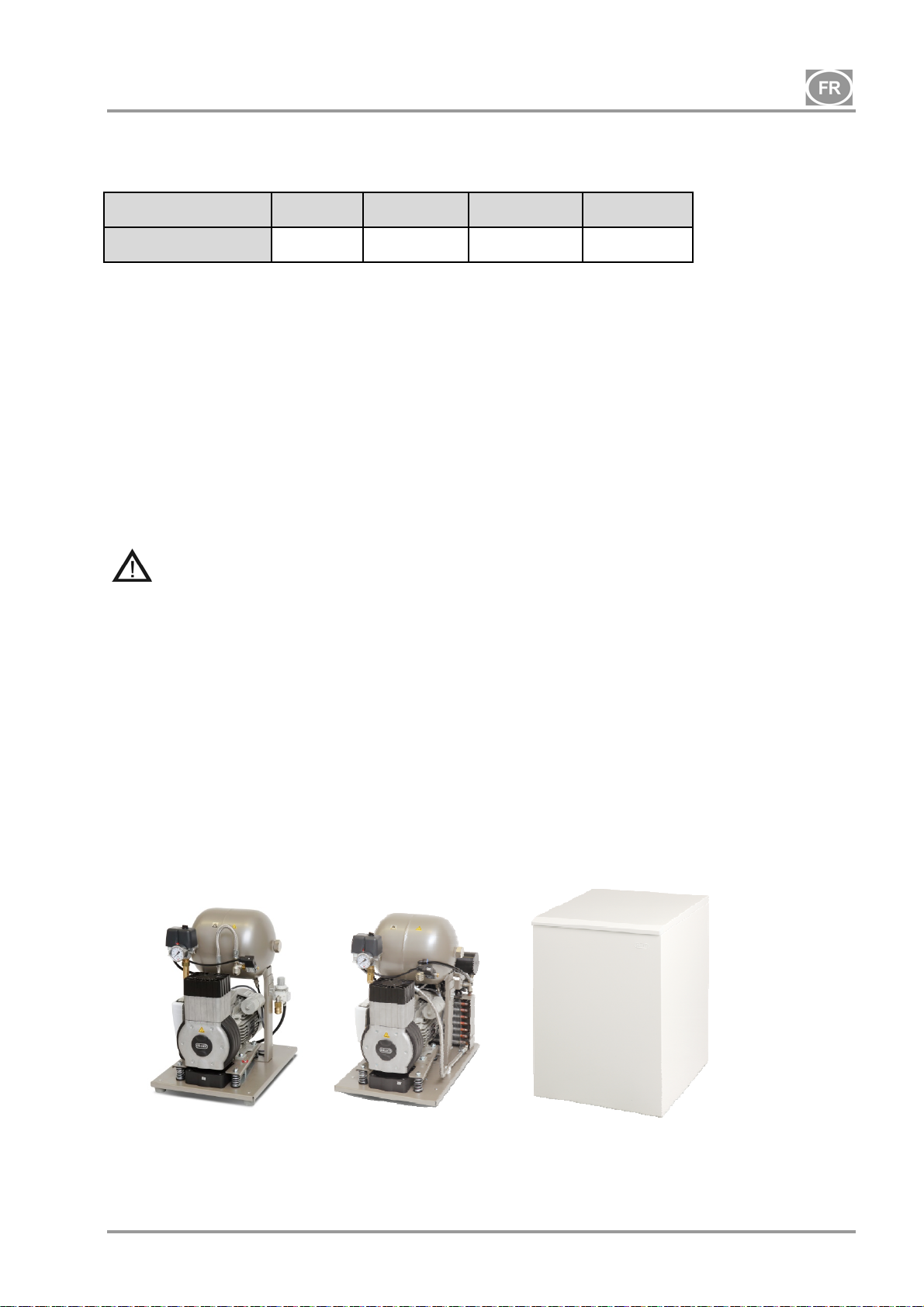
DK50-10
5.1. Correction de la distribution d’air libre (DAL) en raison de l’altitude
Tableau de correction DAL
Altitude [mamsl] 0 - 1 500 1 501 - 2 500 2 501 - 3 500 3 501 - 4 500
DAL [l/min] DAL x 1 DAL x 0,8 DAL x 0,71 DAL x 0,60
Sortie DAL soumise aux conditions :
Altitude : 0 MASL Température : 20 °C
Pression atmosphérique : 101 325 Pa Humidité relative : 0 %
6. DESCRIPTION DU PRODUIT
6.1. Différents modèles et leurs utilisations
Le compresseur est utilisé comme source d’air comprimé, propre et exempt d’huile pour alimenter les
équipements, les outils et les appareils dentaires dans les laboratoires où les paramètres et les propriétés
de l’air comprimé conviennent à l’application spécifique.
L’air comprimé fourni par le compresseur ne peut être utilisé avec les appareils artificiels de
ventilation pulmonaire sans filtration supplémentaire.
Toute utilisation de l’équipement en dehors du cadre défini dans les présentes est considérée comme
inappropriée. Le fabricant n’est pas responsable des dommages ou blessures résultant d’une utilisation non
recommandée.
6.2. Description
Les modèles de compresseur sont conçus pour les utilisations suivantes :
Compresseur DK50-10 Z : un compresseur sur support pour installation autonome dans un espace donné
Compresseur DK50-10 Z/K : un compresseur sur support avec unité de condensation et de filtration (KJF1)
Compresseur DK50-10 Z/M : un compresseur sur support avec un sécheur d’air
Compresseur DK50-10 S : un compresseur confiné avec réduction efficace du bruit pour installation dans
les bureaux
Compresseur DK50-10 S/K : un compresseur confiné avec unité de condensation et de filtration (KJF1)
Compresseur DK50-10 S/M : un compresseur confiné avec sécheur d’air
DK50-10 Z
DK50-10 Z/M
DK50-10 S
DK50-10 S/M
08/2017 - 65 - NP-DK50-1_08-2017-MD
Page 68
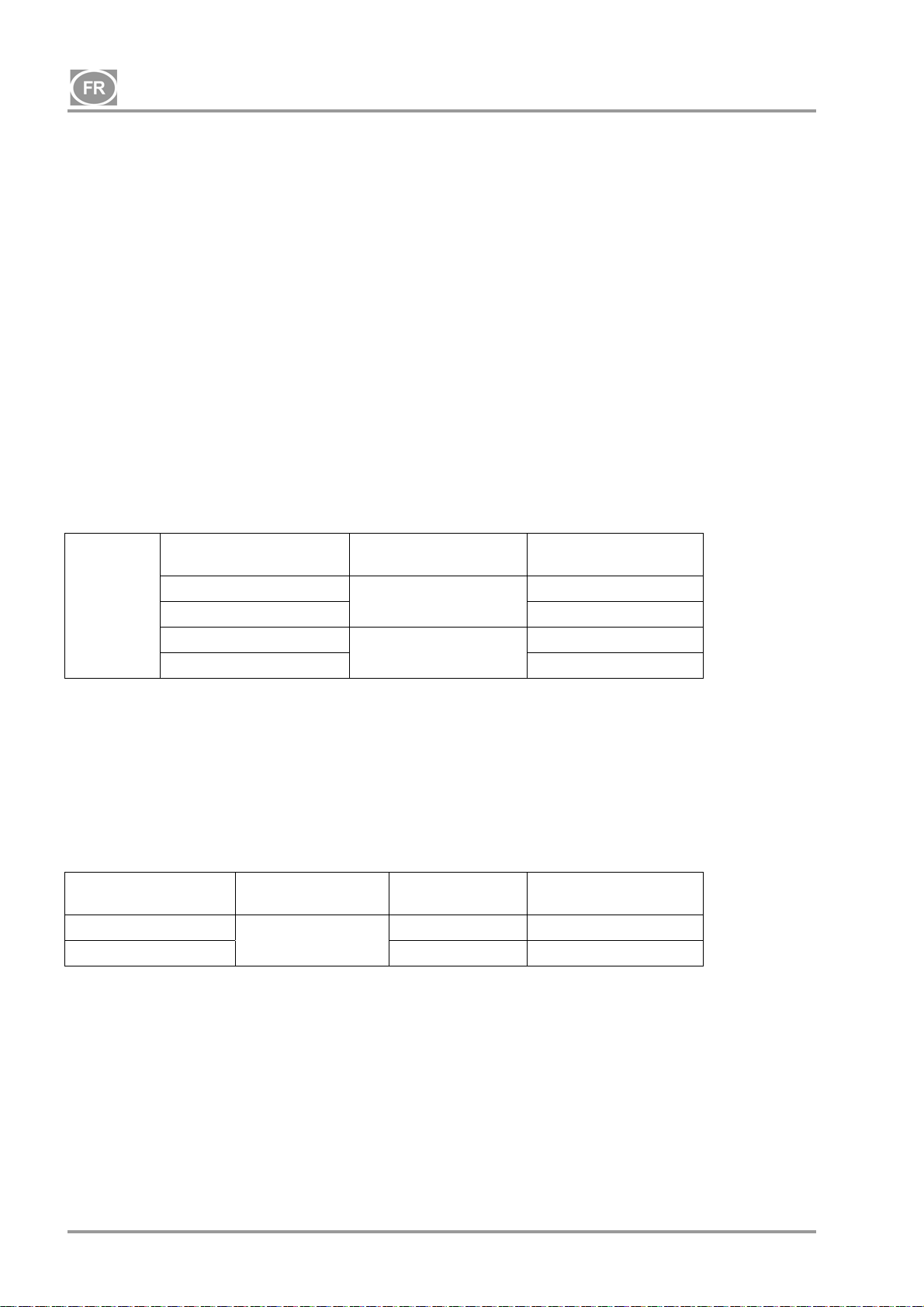
DK50-10
6.3. Accessoires
Les accessoires non inclus dans la commande standard doivent être commandés séparément !
6.3.1 Purge automatique des condensats
La purge automatique des condensats (AOK) purge automatiquement les condensats du réservoir d’air du
compresseur selon un intervalle de temps prédéfini. La purge de condensat (AOK) est un accessoire
indiqué pour les modèles de compresseurs sans sécheurs.
6.3.2 Ensemble de filtres
Les compresseurs peuvent être équipés d’un ensemble de filtres sur la sortie d’air comprimé, si spécifié.
L’ensemble de filtres peut être équipé d’un régulateur de pression. Les ensembles de filtres sont des
accessoires appropriés pour tous les compresseurs spécifiés ci-dessus.
REMARQUE : Si un niveau plus élevé de filtration d’air est nécessaire, cette spécification doit être
convenue avec le fournisseur et clairement mentionnée lors de la commande.
o
d’article du kit
604013245-000
604013234-000
ENSEMBLE
DE
FILTRES
Niveau de filtrage Régulateur de pression N
Oui
5 µm 604013233-000
0,3 µm
No
0,01 µm 604013235-000
6.3.3 Unité de condensation et de filtration (KJF)
Le compresseur peut également être équipé d’une unité de condensation et de filtration (KJF-1 ou KJFR-1).
Les unités KJF-1 ou KJFR-1 garantissent que l’air comprimé provenant du réservoir d’air est refroidi dans le
refroidisseur et que le condensat est capturé dans le filtre et automatiquement séparé du circuit d’air
comprimé. L’air comprimé est filtré simultanément.
Unité de condensation
et de filtration
Niveau de filtrage
KJF-1
5µm
KJFR-1 Oui
Régulateur de
pression
No
o
d’article du kit
N
450001011-001
450001011-002
NP-DK50-1_08-2017-MD - 66 - 08/2017
Page 69
DK50-10
7. FONCTIONNALITÉ DU PRODUIT
Compresseur (Fig. 1)
L’agrégat du compresseur (1) aspire l’air ambiant à travers le filtre d’entrée (8) et le comprime via le clapet
anti-retour (3) vers un réservoir d’air (2) à partir duquel l’appareil aspire l’air comprimé. Si la pression dans
le réservoir d’air baisse à la pression de commutation, le pressostat (4) allume le compresseur et le
compresseur fournit de l’air comprimé au réservoir d’air jusqu’à ce qu’il atteigne la pression de coupure,
moment auquel le compresseur s’éteint. Le tuyau de pression est évacué à travers l’électrovanne de
décharge (13) une fois que l’unité du compresseur est éteinte. La soupape de sûreté (5) empêche la
montée de la pression à l’intérieur du réservoir d’air au-delà de la valeur maximale permise. La soupape de
vidange (7) évacue le condensat du réservoir d’air. L’air comprimé, filtré, propre et exempt d’huile est stocké
dans le réservoir d’air et prêt à l’emploi.
Le condensat doit être évacué du réservoir d’air à intervalles réguliers (voir chapitre 18).
Compresseur avec sécheur à membrane (Fig. 3)
L’agrégat du compresseur (1) aspire l’air à travers un filtre d’entrée (8), le comprime et l’envoie au
refroidisseur (14) à travers le filtre (15) vers le sécheur (9) et l’air propre et sec est ensuite conduit à travers
le clapet anti-retour (3) vers le réservoir d’air (2). Une partie de l’air contourne le sécheur avec l’humidité
saisie, ce qui se manifeste comme un courant d’air doux le long du corps du sécheur (9). Le condensat du
filtre est automatiquement évacué à intervalles réguliers dans le récipient via l’électrovanne de décharge de
condensat (16). Le sécheur assure le séchage continu de l’air comprimé. La soupape de vidange (7) évacue
le condensat du réservoir d’air lors du contrôle de la performance de séchage. L’air comprimé, filtré, propre
et exempt d’huile est stocké dans le réservoir d’air et prêt à l’emploi.
Les compresseurs avec sécheur ne nécessitent pas d’opérateur. Les récipients sous pression ne
nécessitent pas de vidange.
Compresseur avec unité de condensation et de filtration (Fig. 2)
L’agrégat du compresseur (1) aspire l’air ambiant à travers le filtre d’entrée (8) et le comprime dans le
réservoir d’air (2) protégé par le clapet anti-retour (3). L’air comprimé du réservoir d’air circule dans un
refroidisseur (10) qui le refroidit. L’humidité condensée est captée dans le filtre (11) et séparée
automatiquement sous forme de condensat (12) dans le récipient. L’air comprimé sans traces d’huile est
prêt à l’emploi.
Le condensat doit être évacué du réservoir d’air à intervalles réguliers (voir chapitre 18).
Boîtier du compresseur
Le boîtier insonorisé est compact et assure une circulation suffisante de l’air de refroidissement. Son design
le rend approprié aux installations dans les bureaux et lui permet de s'intégrer parfaitement à d’autres
meubles. Le ventilateur situé sous l’agrégat du compresseur assure le refroidissement approprié du
compresseur et fonctionne avec le moteur du compresseur lorsque le commutateur de température est
activé à des températures supérieures à 40 °C.
Assurez-vous que rien n’entrave la libre circulation de l’air sous le compresseur et autour
de celui-ci. Ne couvrez jamais la sortie d’air chaud située sur la partie supérieure arrière
du boîtier.
En cas d’installation du compresseur sur un plancher mou, notamment un tapis, créez un
espace vide entre la base et le plancher ou entre le coffret et le plancher, par exemple en
calant les pieds avec des supports durs.
Les compresseurs de 10 bar sont équipés d’un horomètre (Fig. 4).
08/2017 - 67 - NP-DK50-1_08-2017-MD
Page 70
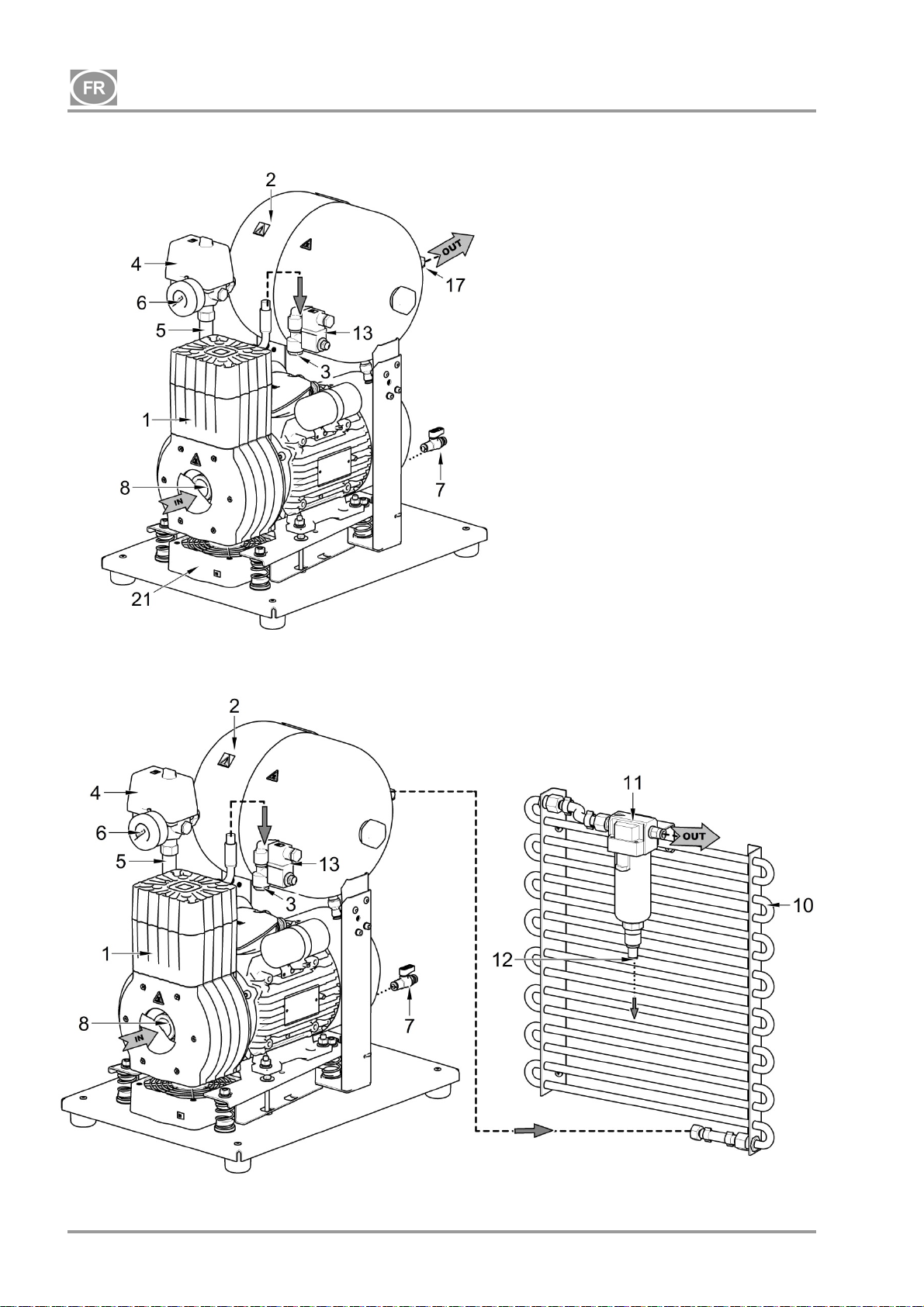
DK50-10
Fig. 1 – Compresseur DK50-10 Z
Fig. 2 – Compresseur DK50-10 Z/K avec condensat et unité de filtration KJF1
Description des figures 1 à 4
1. Agrégat du compresseur
2. Réservoir d’air
3. Clapet anti-retour
4. Pressostat
5. Soupape de sûreté
6. Manomètre
7. Soupape de vidange
8. Filtre d’entrée
9. Sécheur
10. Refroidisseur tubulaire
11. Filtre
12. Sortie de condensat
13. Électrovanne
14. Sécheur-refroidisseur
15. Filtre
16. Soupape avec minuterie
17. Prise d’air comprimé
18. Commutateur du disjoncteur
19. Récipient
20. Support magnétique
21. Ventilateur
22. Commutateur
23. Horomètre
24. Raccord
25. Boîtier de ventilateur
NP-DK50-1_08-2017-MD - 68 - 08/2017
Page 71
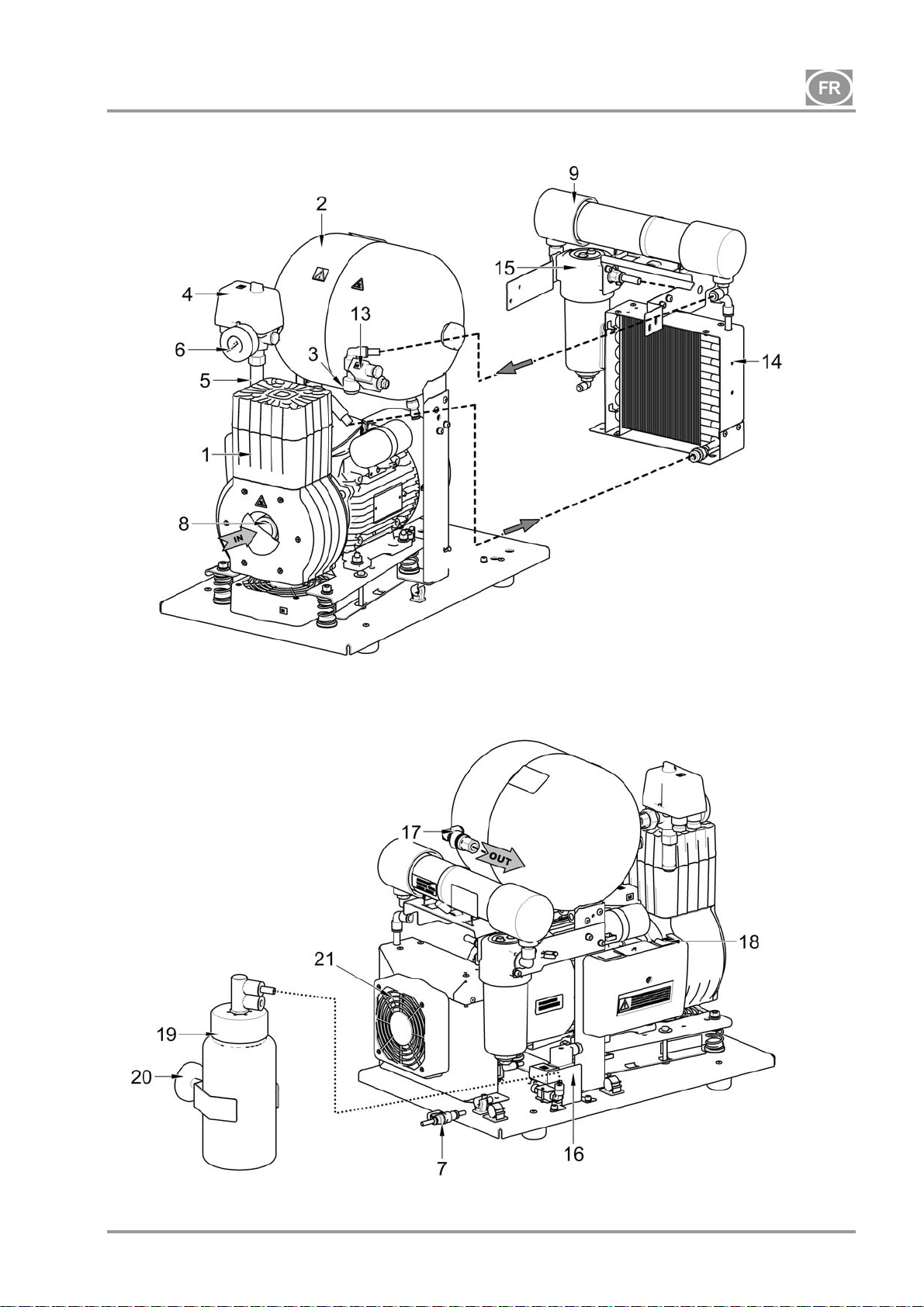
DK50-10
Fig. 3 – Compresseur DK50-10 Z/M avec sécheur
08/2017 - 69 - NP-DK50-1_08-2017-MD
Page 72
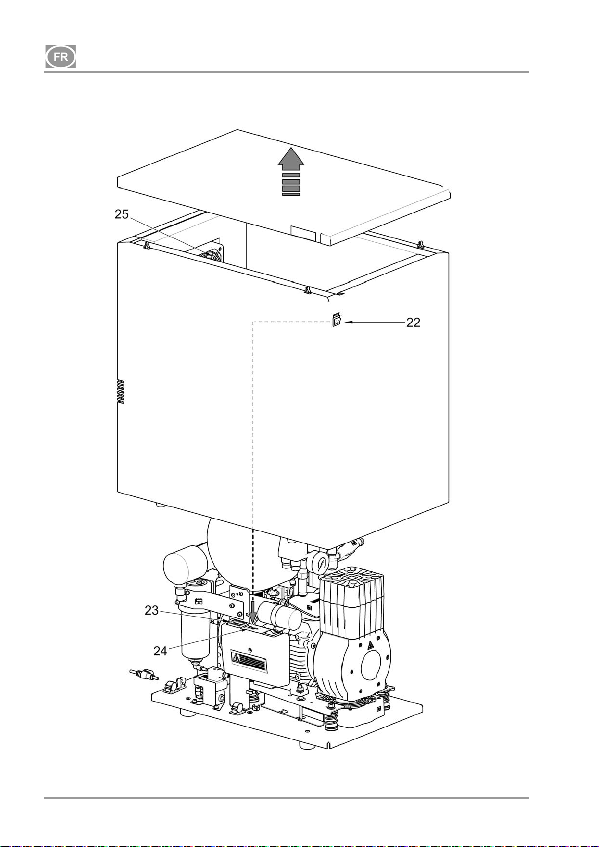
DK50-10
Fig. 4 – Compresseur DK50-10 S/M de 10 bar
NP-DK50-1_08-2017-MD - 70 - 08/2017
Page 73
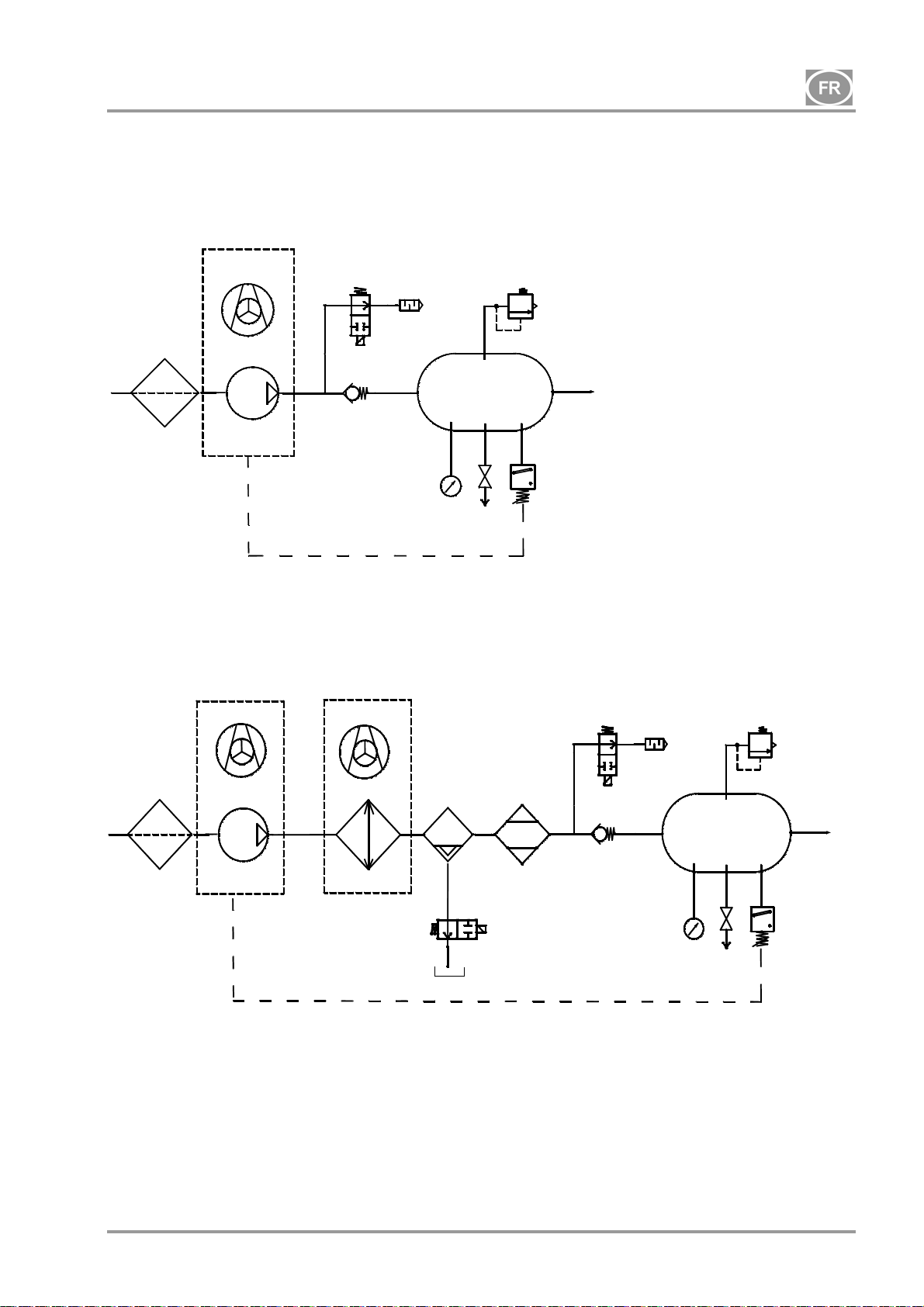
DK50-10
8. SCHÉMA PNEUMATIQUE
DK50-10 Z, DK50-10 S
1
DK50-10 Z/M, DK50-10 S/M
1
Légende des schémas d’air comprimé
1. Filtre d’entrée
2. Compresseur
3. Ventilateur
4. Soupape de décharge
5. Silencieux
6. Clapet anti-retour
7. Manomètre
8. Pressostat
3
4
2
3
2
6
3
12
14
9
8
4
6
5
10
11
7
9
8
5
10
11
7
13
16
15
9. Soupape de sûreté
10. Réservoir d’air
11. Soupape de vidange
12. Refroidisseur
13. Filtre coalescent
14. Sécheur à membrane
15. Réservoir pour condensat
16. Électrovanne de purge du condensat
08/2017 - 71 - NP-DK50-1_08-2017-MD
Page 74
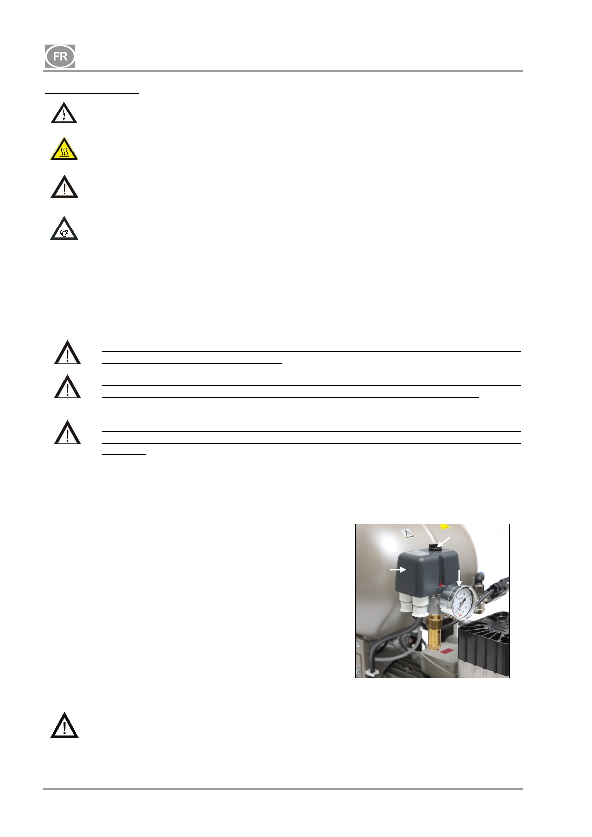
DK50-10
FONCTIONNEMENT
En cas d’urgence, débranchez le compresseur du secteur (retirer la prise secteur).
Le compresseur comporte des surfaces chaudes.
Il présente un risque de brûlure ou d’incendie en cas de contact.
En cas d’utilisation prolongée du compresseur, la température du boîtier peut dépasser
Les réglages de la pression de travail du pressostat effectués par le fabricant ne peuvent pas être
modifiés. Le fonctionnement du compresseur à une pression de travail inférieure à la pression de
commutation indique une forte consommation d’air de l’appareil raccordé (voir chapitre
Dysfonctionnements)
40 °C. À ce stade, le ventilateur de refroidissement s’allume automatiquement. Après avoir
refroidi l’espace intérieur à moins de 32 °C, le ventilateur s’éteint.
Démarrage automatique : lorsque la pression dans le réservoir baisse et s’approche de la
limite inférieure du pressostat, le compresseur se met automatiquement en marche. Le
compresseur s’éteint automatiquement après avoir atteint la limite supérieure du
pressostat.
Pour obtenir des performances de séchage optimales, vous devez absolument respecter
les conditions d’utilisation indiquées !
Lorsque le sécheur fonctionne à une pression inférieure à la pression de travail
minimum, les performances de séchage et le point de rosée atteints diminuent !
Toute utilisation du compresseur à une température ambiante supérieure à la
température de travail maximale est susceptible d’endommager irrévocablement le
sécheur !
9. MISE SOUS TENSION DU COMPRESSEUR
(Fig. 5)
Allumez le compresseur au niveau du pressostat (2) en tournant le
commutateur principal (3) sur la position « l ». Vérifiez que le
commutateur du disjoncteur est sur la position « l ». Lorsqu’il est
sur la position « 0 », tournez le commutateur sur « I » (Fig. 3 –
position 18). Le commutateur (Fig. 4 – position 22) du boîtier des
compresseurs DK50-10 S/M de 10 bar est situé à l’avant du
boîtier ; l’indicateur s’allume en vert. Le compresseur se met en
marche et commence à remplir le réservoir d’air jusqu’à ce que la
pression atteigne la pression de commutation et que le pressostat
arrête le compresseur. Le compresseur fonctionne alors en mode
automatique et est commandé par les réglages de pression du
pressostat contrôlant la mise en marche et l’arrêt de l’appareil en
fonction de la consommation d'air comprimé. Cette pression peut
être contrôlée à partir du manomètre (5). Une tolérance de 10 %
est acceptable. La pression du réservoir d’air ne doit pas dépasser
la pression de fonctionnement maximale autorisée.
Il est interdit de modifier les pressions de
commutation du pressostat des compresseurs.
Le pressostat (2) a été réglé par le fabricant et tout autre réglage d’augmentation ou de réduction de
la pression peut uniquement être effectué par un expert qualifié et formé par le fabricant.
2
Fig. 8
Fig.5
3
5
NP-DK50-1_08-2017-MD - 72 - 08/2017
Page 75
DK50-10
INSTALLATION
10. CONDITIONS D’EMPLOI
Les compresseurs doivent être installés et utilisés uniquement dans des environnements secs, bien
ventilés et propres, avec des paramètres environnementaux conformes aux exigences spécifiées au
chapitre 5, Caractéristiques techniques. Le compresseur doit être installé de sorte à être accessible en
permanence pour être utilisé et entretenu. Assurez-vous que la plaque signalétique de l’appareil est
facilement accessible.
Le compresseur doit être posé sur un support plat et suffisamment stable (attention au poids du
compresseur, voir chapitre 5, Caractéristiques techniques).
Les compresseurs ne doivent pas être utilisés à l’extérieur ou dans des environnements humides. Évitez
d’utiliser le compresseur en présence de gaz explosifs, de poussières ou de liquides inflammables.
Avant de raccorder le compresseur aux installations médicales, le fournisseur doit vérifier sa conformité
aux exigences relatives à son utilisation. Pour plus de détails sur ce sujet, merci de bien vouloir vous
référer aux Caractéristiques techniques. La classification et l’attestation de conformité lors de
l’assemblage doivent être confiées au fabricant ou au fournisseur du produit final.
Toute utilisation autre que celle décrite dans le présent manuel n’est pas couverte par la garantie, et le
fabricant n’est pas responsable des dommages qui pourraient en résulter. L’opérateur / l’utilisateur en
assume la totalité des risques.
Le compresseur doit être installé et mis en fonctionnement pour la toute première fois par
un professionnel qualifié. Ce professionnel est tenu de former le personnel à l’utilisation
et à la maintenance de l’appareil. Sa signature apposée au certificat d'installation vaut
attestation de bonne installation et de formation du personnel.
Avant l’installation, assurez-vous d’enlever tous les emballages de transport et les
stabilisateurs afin de ne pas risquer d’endommager le produit.
Mise en garde ! Pendant l’utilisation, le compresseur chauffe. L’opérateur s’expose à des
brûlures en cas de contact avec l'appareil. En outre, un incendie peut se produire si le
compresseur entre en contact avec un matériau inflammable.
Conditions d’utilisation ambiantes
Température : + 5 à + 40 °C
Humidité relative maximale : 70 %
Humidité absolue maximale : 15 g/m
3
08/2017 - 73 - NP-DK50-1_08-2017-MD
Page 76
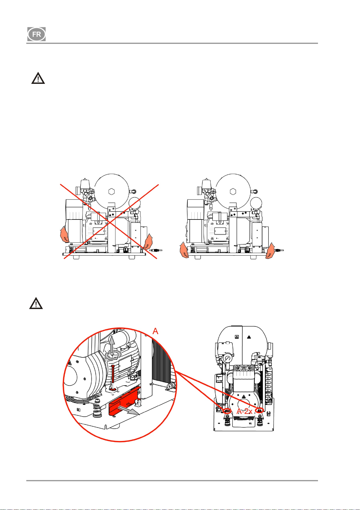
DK50-10
11. POSITIONNEMENT DU COMPRESSEUR
L’équipement doit uniquement être installé par un professionnel qualifié.
Défaites l’emballage du compresseur.
11.1. Manipulation et libération du compresseur
Positionnez le compresseur sur le site de fonctionnement choisi (Fig. 6)
Fig. 6
Retirez les stabilisateurs de transport des agrégats. (Fig. 7)
Retirez tous les dispositifs utilisés pour fixer les compresseurs une fois que le compresseur a été
installé et monté sur le site d’installation final !
Fig. 7
NP-DK50-1_08-2017-MD - 74 - 08/2017
Page 77
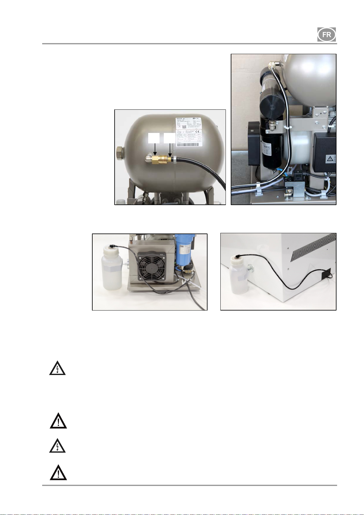
DK50-10
12. RACCORDS PNEUMATIQUES
12.1. Sortie d’air comprimé (Fig. 8)
Raccordez un tuyau de pression dont une extrémité possède
un raccord rapide coulissant (1) à la sortie d’air comprimé (2) du
compresseur et raccordez le tuyau au système d’air comprimé
ou directement à l’appareil, dans ce cas, à l’appareil dentaire.
Fig. 8
12.2. Sortie de condensat (Fig. 9)
2 1
Raccordez le tuyau de vidange du condensat au récipient de condensat des compresseurs avec
sécheur.
Fig. 9
Pour certains compresseurs (sans sécheur), faites passer le tuyau à travers l’ouverture de la paroi
arrière du boîtier.
13. BRANCHEMENTS ÉLECTRIQUES
L’appareil est équipé d’une prise mise à la terre. Branchez la fiche secteur sur une prise secteur.
Vérifiez la conformité de l’appareil aux codes électriques locaux. La fréquence et la
tension du secteur doivent être conformes aux informations mentionnées sur l’étiquette
de l’appareil.
Placez la prise à un endroit facilement accessible, de sorte à pouvoir débrancher l’appareil en toute
sécurité en cas d’urgence.
Le branchement au boîtier de distribution de l’énergie électrique doit être de 16 A au maximum.
Le boîtier des compresseurs DK50-10S/M de 10 bar est équipé d’un ventilateur de
refroidissement et d’un commutateur. Le boîtier doit être raccordé à l’aide du cordon à raccord
fourni au raccord correspondant situé sur le panneau électrique du compresseur. (Fig. 4)
Assurez-vous que le câble électrique ne touche pas les composants chauds du
compresseur. Risque de décharge électrique !
Si un cordon électrique ou un tuyau d’air est endommagé, il doit être remplacé
immédiatement.
08/2017 - 75 - NP-DK50-1_08-2017-MD
Page 78
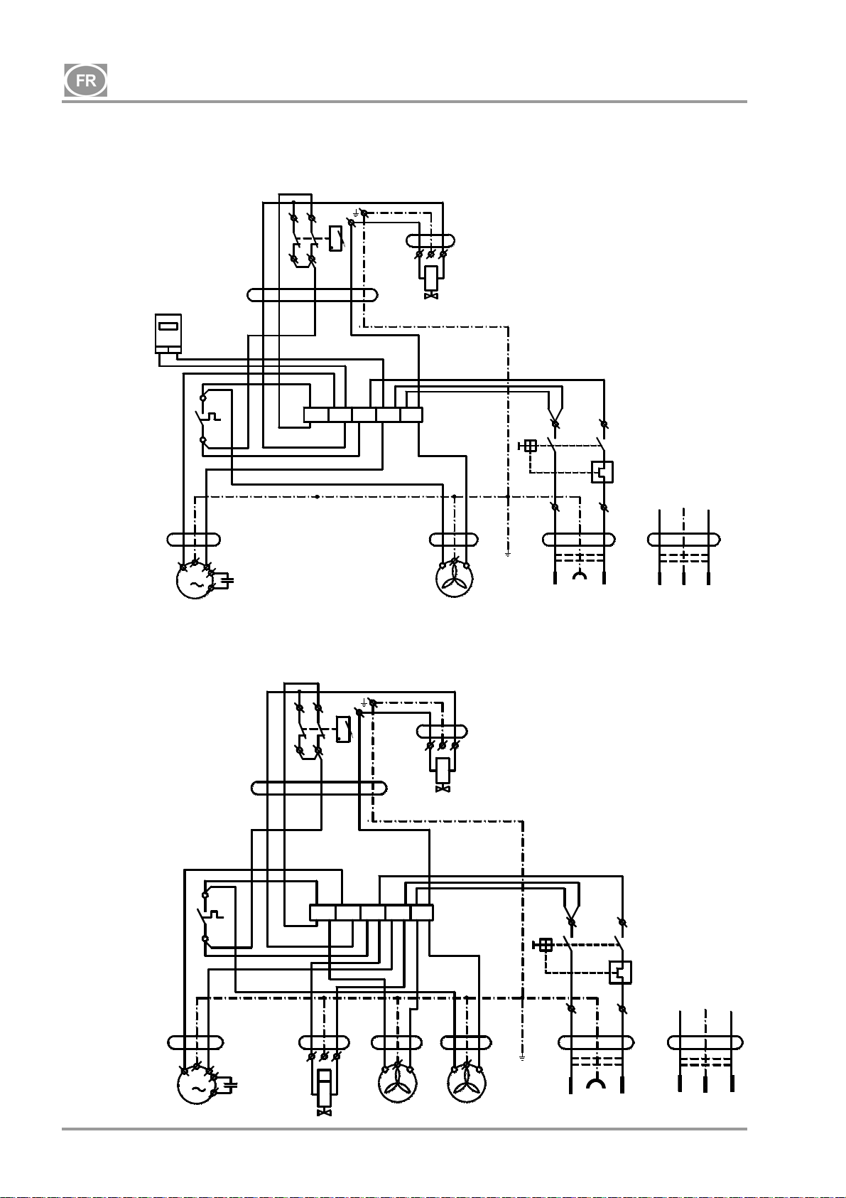
DK50-10
14. SCHÉMA DE BRANCHEMENT
DK50-10 Z, DK50-10 S 5-7 bar, 6-8 bar, 8-10 bar
1/N/PE ~ 115V / 60 Hz
~ 230V / 50/60 Hz
00000
bk bu
P1*
bk
B2
40°C
bk
5G1
bn gy
X1
3G1
1
bk-1bk-2
M
C1
M1
DK50-10 Z/M, DK50-10 S/M 5-7bar, 6-8 bar
1/N/PE ~ 115V / 60 Hz
~ 230V / 50/60 Hz
5G1
bn gy
bk
B2
40°C
bk
NP-DK50-1_08-2017-MD - 76 - 08/2017
3G1
M
1
M1
bk-1bk-2
3G0,75
C1
X1
bk
1
bk
1
bn
T
B1
p >
3G0,75
bu
2
N
U
B1
p >
bu
2
bu bu
U
3G0,5
N
bn
M4
bu
N
3G0,75
bu
N
E2
bn
M3
bu bu
bn
3G0,5
E1
bn
M3
bu
bn
3G0,5
E1
gnye
gnye
bu bk
bu
F1
3G1,5
CE
bu bk
F1
3G1,5
* - only for 8-10bar version
P1
P2
4
8
gnye
PE
bn
UN
gnye
bu bn
3G1,5
PE
UK
bu
P1
P2
4
8
bu
CE
gnye
PE
bn
UN
gnye
bu bn
3G1,5
UK
PE
UN
UN
Page 79
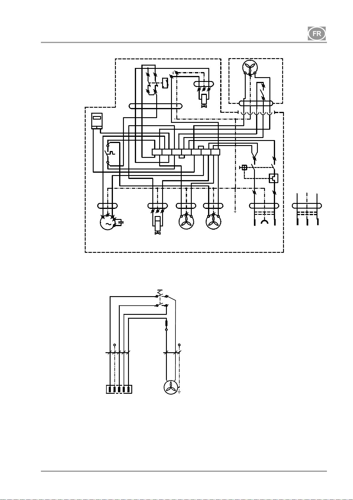
DK50-10
DK50-10 Z/M, DK50-10 S/M 8-10 bar
1/N/PE ~ 230V 50..60Hz
Boîtier du DK50-10 S/M - 10bar
Légende des schémas électriques
~ 115V 60Hz
bn gy
5G1
00000
P1
bkbu
bk
3G1
B2
40°C
bk
bk-1bk-2
M
1
X1
3G0,75
C1
M1
* - only for DK50-10 Z/M version
1/N/PE ~ 230V 50..60Hz
5G1
bn
bk
bu
PE
-S10
gy
-X10
1
N23PE
M1 Moteur du compresseur
E1 Ventilateur du compresseur
E2 Ventilateur du sécheur
M3 Électrovanne
B2 Commutateur de température
E3, E10 Boîtier de ventilateur
X10, X2 Raccord
B1
p >
bk
bu
2
1
U
U
3G0,75
bn
bu
M3
N
N
N
*
gnye
bn
bu bu bu
T
2a
1a
3G0.5
M4
2
1
1
bn
3G0,5
bu
bn
E2
PE
3G0,5
bu
bn
E1
-E10
C1 Condensateur
B1 Pressostat
X1 Barrette de fixation
F1 Commutateur protégé
M4 Soupape de vidange du condensat
P1 Horomètre
S1 Commutateur
E3
S1
bu
gy
bk
5G1
N
bu
F1
bn
1
bk
bk
bu bk
bu
P2
8
gnye
3G1,5
PE
32
bk
P1
4
bn
CE UK
1 - Compessor
1- Compresseur
2 - Box
2- Boîtier
2
X2
UN
1
gnye
bu bn
3G1,5
PE
UN
08/2017 - 77 - NP-DK50-1_08-2017-MD
Page 80
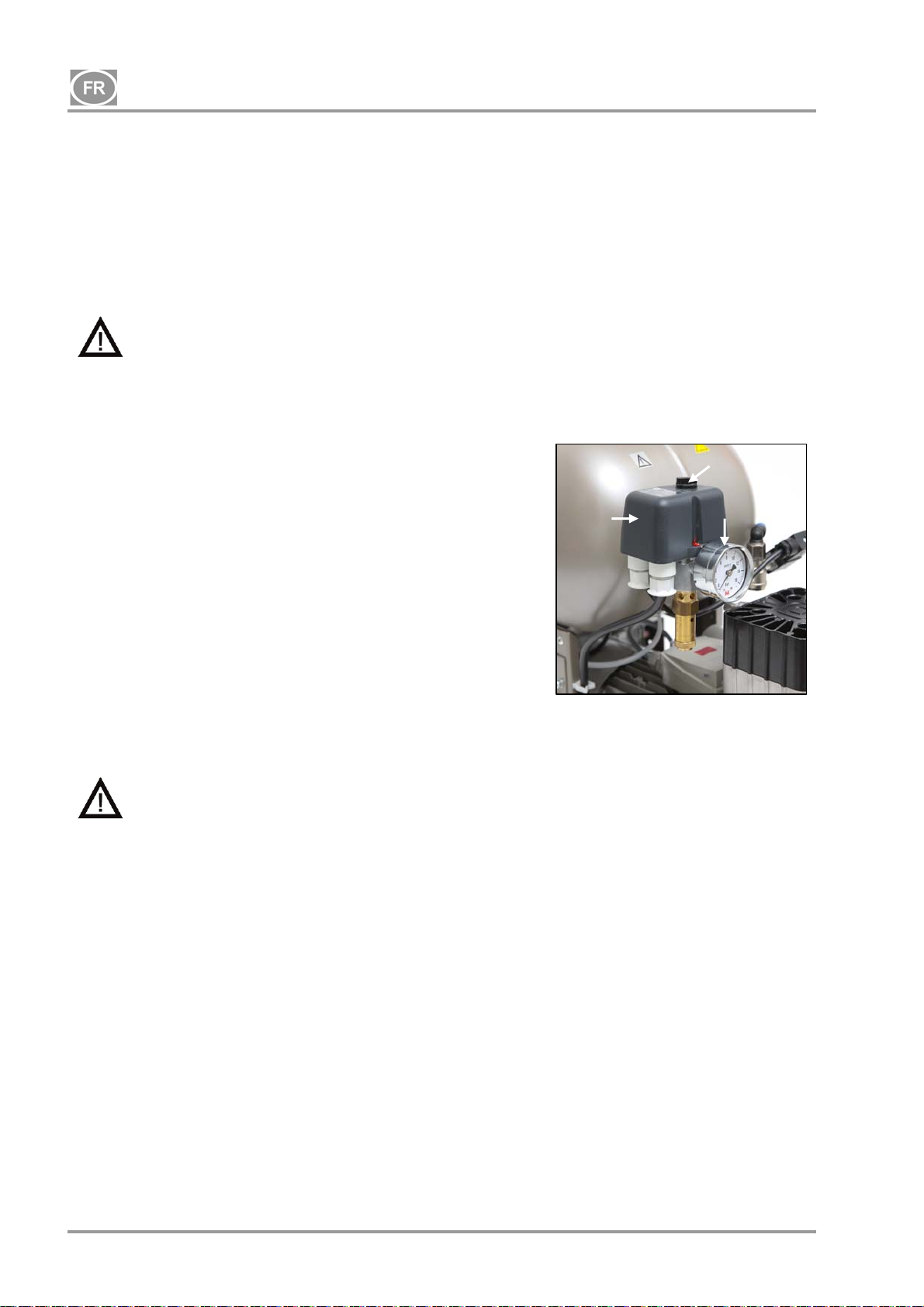
DK50-10
15. MISE EN SERVICE
(Fig. 10)
Assurez-vous de retirer les stabilisateurs de transport.
Vérifiez que tous les raccords de conduite d’air comprimé sont bien fixés.
Vérifiez que le compresseur est correctement alimenté.
Vérifiez que le commutateur du disjoncteur est sur la position « l ». S’il est sur la position « 0 », tournez le
commutateur principal sur la position « I ». (Fig. 3)
Vérifiez que le boîtier du compresseur DK50-10S/M (modèles de 8 à 10 bar uniquement) est connecté au
compresseur à l’aide d’un câble à raccord.
Le compresseur n’est pas doté d’une alimentation électrique de secours.
16. MISE SOUS TENSION DU COMPRESSEUR
(Fig. 10)
Allumez le compresseur au niveau du pressostat (2) en tournant le
sélecteur (3) vers la position « I ». Vérifiez que le commutateur du
disjoncteur est sur la position « l ». Lorsqu’il est sur la position
« 0 », tournez le commutateur sur « I » (Fig. 3 – position 18). Le
commutateur (Fig. 4 – position 22) du boîtier des compresseurs
2
DK50-10S/M de 10 bar est situé à l’avant du boîtier ; l’indicateur
s’allume en vert. Le compresseur se met en marche et commence
à remplir le réservoir d’air jusqu’à ce que la pression atteigne la
pression de commutation et que le pressostat arrête le
compresseur. Le compresseur fonctionne alors en mode
automatique et est commandé par les réglages de pression du
pressostat contrôlant la mise en marche et l’arrêt de l’appareil en
fonction de la consommation d'air comprimé. Cette pression peut
être contrôlée à partir du manomètre (5). Une tolérance de 10 %
est acceptable. La pression du réservoir d’air ne doit pas dépasser
Fig. 10
la pression de fonctionnement maximale autorisée.
Il est interdit de régler la plage de pression du pressostat du compresseur. Le
pressostat (2) a été réglé par le fabricant et les modifications de ses paramètres peuvent
uniquement être effectuées par un technicien qualifié.
Compresseur – lors de la première mise en service, le compresseur remplit le réservoir d’air jusqu’à ce que
la pression de commutation et le pressostat arrêtent le compresseur. Le compresseur fonctionne en mode
automatique et le pressostat commande sa mise en marche et son arrêt en fonction de la consommation
d'air comprimé.
3
5
Compresseur avec sécheur – le compresseur fonctionne de la même manière que ci-dessus, seul l'air
comprimé passe à travers un refroidisseur pour éliminer l'humidité de l'air comprimé.
Compresseur avec unité de condensation et de filtration (KJF-1) – lors de l’utilisation de l’appareil, l’air
comprimé traverse l’unité KJF-1 qui le refroidit. Le liquide filtré et condensé est capté et automatiquement
évacué dans un récipient.
17. ARRÊT DU COMPRESSEUR
L’arrêt du compresseur pour entretien ou pour toute autre raison s’effectue à partir du pressostat (2) en
tournant le sélecteur (3) sur la position « 0 » et en débranchant la fiche secteur de la prise. Cette
opération permet de mettre le compresseur hors tension. Ensuite, ouvrez la soupape de vidange (Fig. 1)
pour évacuer totalement la pression du réservoir d’air.
NP-DK50-1_08-2017-MD - 78 - 08/2017
Page 81
DK50-10
MAINTENANCE
18. ENTRETIEN DE L’APPAREIL
Avertissement !
L’opérateur doit s’assurer que des tests répétés de l’appareil soient effectués au moins une fois
tous les 24 mois (EN 62353) ou à des intervalles définis par les réglementations nationales
applicables. Un procès-verbal des résultats de ces tests doit être rempli (p. ex. conformément à la
norme EN 62353, annexe G) avec les méthodes de mesure.
L’appareil a été conçu et fabriqué de manière à réduire au minimum l’entretien. Vous devez effectuer les
travaux suivants pour préserver le fonctionnement correct et fiable du compresseur.
Avant le début des travaux d’entretien du compresseur, vérifiez que ce dernier
est déconnecté de l’appareil pour vous assurer que la personne qui utilise l’appareil n’est
pas en danger et qu’il n’existe aucun risque de dommages matériels !
Les composants (tête, cylindre, tuyau de pression, etc.) sont très chauds pendant et peu
après le fonctionnement du compresseur – évitez de les toucher !
Les travaux de réparation, dépassant le cadre d’un entretien ordinaire, ne peuvent être
effectués que par un technicien qualifié ou par le représentant du fabricant.
Utilisez uniquement les pièces de rechange et les accessoires agréés par le fabricant.
Le port d’une protection oculaire, comme des lunettes par ex., est nécessaire lors de la
vidange de l’air comprimé dans le circuit d’air comprimé (réservoir d’air).
Les travaux ci-après doivent uniquement être effectués par un personnel formé :
AVANT DE DÉBUTER UNE TÂCHE DE MAINTENANCE, IL FAUT D’ABORD éteindre le
compresseur, le débrancher,(débranchez la prise secteur) et vidanger l’air comprimé dans
le réservoir d’air.
Les compresseurs de 10 bar sont équipés d’un horomètre (Fig. 4), utilisé pour contrôler le nombre total
d'heures de fonctionnement.
08/2017 - 79 - NP-DK50-1_08-2017-MD
Page 82

DK50-10
18.1. Intervalles de maintenance
une fois
une
année
Intervalle de temps
Vérifications opérationnelles
de l’appareil
Purge du condensat du
réservoir d'air comprimé **
À niveau d’humidité élevé
Purge du condensat du
réservoir d'air comprimé **
À niveau d’humidité normal
Vérification des fonctions de
l’appareil
Contrôle des fuites au niveau
des branchements et
inspection de l’appareil
Inspection des branchements
électriques
Contrôle du refroidisseur et
du ventilateur
Remplacement de l’élément
filtrant
du filtre du sécheur
Remplacement de l’élément
filtrant du KJF-1
Contrôle de la soupape de
sûreté
Réalisation des « tests
répétés » conformément à la
norme EN 62353
Remplacement de l’agrégat
du filtre d’entrée )*
une fois
un jour
x 18.2 -
une fois
une
semaine
x
x
x
x
x
x
x
x
x
)* les données sont présentées en heures ; si ce n’est pas possible, elles sont considérées en années
)** uniquement pour les compresseurs sans sécheur
une fois
tous les
2 ans
2 000 4 000 6 000 8 000 10 000 12 000
x
x
x x x 18.7 025200126-000
Chapitre
18.5 -
18.5 -
18.6 -
18 -
7 -
18.3 -
18.4 -
18.10 -
18.8 025200304-000
18.9 025200061-000
Nomenclature Effectué par
utilisateur
utilisateur
utilisateur
utilisateur
professionnel
qualifié
professionnel
qualifié
professionnel
qualifié
professionnel
qualifié
professionnel
qualifié
professionnel
qualifié
professionnel
qualifié
professionnel
qualifié
NP-DK50-1_08-2017-MD - 80 - 08/2017
Page 83

DK50-10
18.2. Contrôles opérationnels
Contrôle de l’état de l’agrégat – les agrégats doivent fonctionner normalement sans vibrations ou bruits
excessifs. Résolvez tout problème ou contactez le personnel d’entretien si vous en détectez un.
Contrôle visuel du fonctionnement du ventilateur – assurez-vous que les ventilateurs sont en marche
lors du fonctionnement des agrégats. Résolvez tout problème ou contactez le personnel d’entretien si
vous en détectez un.
Vérifiez que le câble d'alimentation et les flexibles pneumatiques ne sont pas endommagés.
Remplacez les composants endommagés ou contactez le personnel d’entretien.
Contrôle de la température ambiante – la température ambiante doit être inférieure à la limite de
température (40 °C). Refroidissez l'espace si la température est élevée.
Sur les compresseurs avec sécheur – ouvrez le bouchon du réservoir de condensat pour purger le
condensat.
18.3. Contrôle des fuites d’air comprimé au niveau des branchements et de l’appareil
Contrôle des fuites :
Vérifiez l’étanchéité des conduites d’air comprimé lorsque le compresseur est en marche et sous
pression (et non pendant la ventilation de régénération).
Utilisez un analyseur de fuites ou de l’eau savonneuse pour vérifier la présence de fuites sur tous les
joints et raccords. Resserrez ou refermez les branchements où des fuites sont présentes.
Contrôle de l’équipement :
Vérifiez l’état de fonctionnement normal et les niveaux sonores de l’agrégat du compresseur.
Contrôle du fonctionnement du ventilateur – les ventilateurs doivent fonctionner pendant les cycles de
travail définis du compresseur.
Contrôle du fonctionnement du commutateur de température (B2) – chauffez le commutateur de
température à une température supérieure à 40 °C (p. ex. à l’aide d’un pistolet thermique, en évitant de
tordre les pièces en plastique à proximité). Le ventilateur EV1 (et EV2 pour un compresseur avec
sécheur) démarre dès que la température atteint 40 °C tant que l'alimentation est connectée au
compresseur.
Vérification de l'état du filtre – les filtres doivent être intacts et suffisamment propres.
Vérifiez l’état de l’agrégat lui-même et assurez-vous qu’aucune contamination ne se produise à
l’intérieur du carter ou qu’aucun jeu du vilebrequin n’est présent.
Remplacez les pièces défectueuses au besoin.
18.4. Inspection des branchements électriques
Vérifiez tous les branchements électriques de l’appareil lorsque le secteur est débranché !
Inspection
Vérifiez la fonction mécanique du commutateur principal.
Vérifiez que le câble d’alimentation et les câbles connectés ne sont pas endommagés.
Inspectez visuellement le branchement de chaque câble de la barrette de fixation.
Inspectez toutes les bornes à vis du conducteur de protection PE mis à la terre vert et jaune.
08/2017 - 81 - NP-DK50-1_08-2017-MD
Page 84
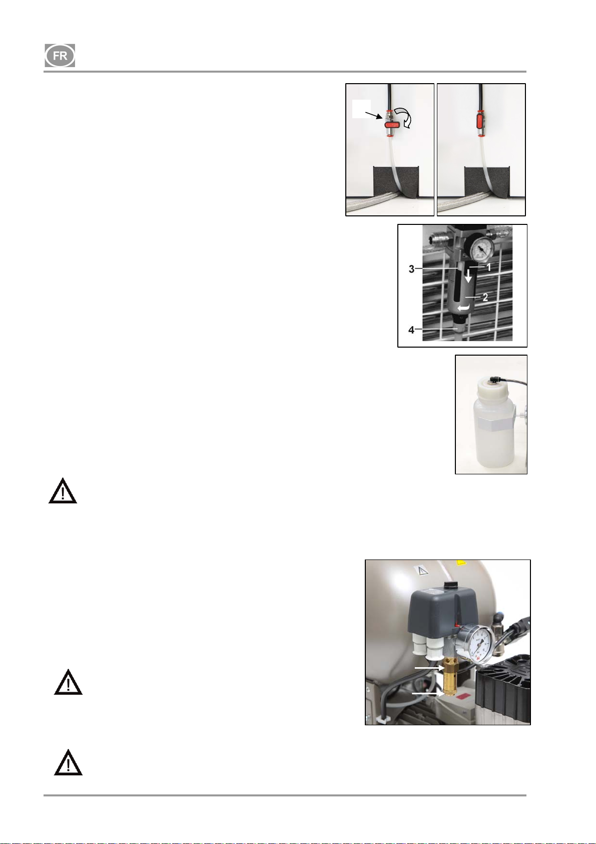
g
DK50-10
18.5. Soupape de vidange du condensat
Compresseurs (Fig. 11)
1
Il est recommandé d’évacuer le condensat du récipient sous
pression lors du fonctionnement régulier. Arrêtez le compresseur
à partir du secteur et réduisez la pression jusqu’à 1 bar
minimum, par exemple en évacuant de l'air à travers l'appareil
raccordé. Placez le tuyau avec la soupape de vidange dans un
récipient préparé en avance, vidangez le condensat du réservoir
en ouvrant la soupape de vidange (1).
Fig. 11
Compresseur avec unité de condensation et de filtration
(Fig. 12)
Lors de l’exploitation régulière, la condensation est
automatiquement évacuée par la soupape de décharge du filtre
de l’unité de condensation. Pour vérifier si la vidange
automatique fonctionne correctement, ouvrez la soupape (4) du
récipient de purge (2) en la tournant vers la gauche. Vidangez
une petite quantité de condensats du récipient. Refermez la
soupape (4) en la tournant vers la droite.
Les deux types de compresseurs peuvent être équipés d’une
Fig. 12
purge de condensat automatique située sur la purge de
condensat du réservoir d’air qui permet d’évacuer le condensat
sans l’intervention de l'opérateur (voir chapitre Contenu de la
livraison – Accessoires).
Compresseurs avec sécheur d’air (Fig. 13)
Le condensat des compresseurs avec sécheur d’air est
automatiquement évacué dans un récipient. Le récipient doit
être vidangé régulièrement, voir chapitre 18.2.
Fig. 13
LES OPÉRATIONS SUIVANTES SONT OBLIGATOIRES AVANT TOUTE VÉRIFICATION DE
SUIVI :
Pour les compresseurs DK50-10S et DK50-10S/M avec boîtier, retirez/soulevez le boîtier.
Pour les compresseurs DK50-10S/M de 10 bar avec boîtier, retirez le couvercle du boîtier,
débranchez le raccord du boîtier du raccord du compresseur et retirez/soulevez le boîtier.
18.6. Contrôle de la soupape de sûreté
(Fig. 14)
Lors de la mise en service du compresseur, assurez-vous du bon
fonctionnement de la soupape de sûreté. Tournez la vis (2) de la
soupape de sûreté (1) plusieurs fois à gauche jusqu’à ce que l’air
s’échappe de la soupape de sûreté. Ne laissez l’air s’échapper
qu’un court instant. Tournez la vis (2) vers la droite jusqu’à la
butée pour fermer la soupape.
La soupape de sûreté ne doit pas être utilisée pour
1
évacuer la pression du réservoir d'air. Cela
pourrait endommager la soupape de sûreté. La
2
vanne est réglée à la pression maximale autorisée
par le fabricant. Il est interdit de modifier ces
réglages !
Fi
.14
Avertissement ! L’air comprimé peut être dangereux. Portez des lunettes de protection
lors de l’évacuation de l’air. L'air comprimé peut endommager les yeux ou causer des
problèmes de vision.
NP-DK50-1_08-2017-MD - 82 - 08/2017
Page 85
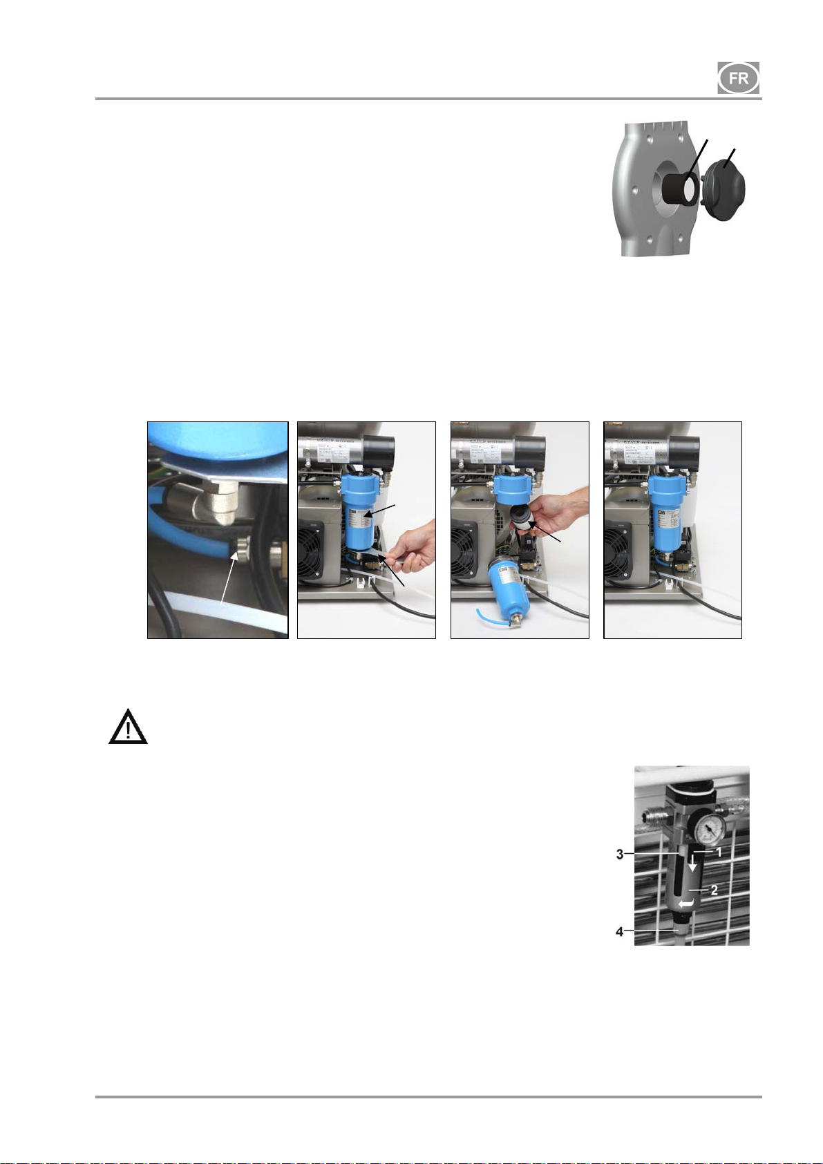
DK50-10
18.7. Remplacement du filtre d’entrée
(Fig. 15)
Tirez le bouchon en caoutchouc (2) à la main.
Retirez le filtre d’entrée encrassé (1).
Insérez un nouveau filtre et refermez le bouchon en caoutchouc.
18.8. Remplacement de l’élément filtrant
Fig. 15
(Fig. 16)
Retirez le tuyau (1) du raccord rapide.
À l’aide d’une clé (2), desserrez le corps de filtre (3) et retirez-le.
Tirez l’élément filtrant (4) vers le bas pour le retirer.
Insérez un nouvel élément filtrant.
Réinstallez le corps de filtre.
Serrez doucement le corps de filtre à l’aide d’une clé.
Réinstallez le tuyau sur le raccord rapide.
Fig. 16
1
3
2
18.9. Remplacement des éléments filtrants de l'unité KJF-1
4
Avant toute intervention sur l’appareil, réduisez à zéro la pression du réservoir d’air et
débranchez l’appareil du secteur.
(Fig. 17)
Replacez le filtre à l’intérieur de la purge de condensat
automatique lorsque l’unité de condensat fonctionne
normalement.
Relâchez le loquet (1) du corps de filtre en tirant vers le bas,
puis tournez le couvercle du filtre (2) vers la gauche et
retirez-le.
Dévissez le support de filtre (3) en le tournant vers la
gauche.
Placez et fixez le nouveau filtre en tournant le support de
filtre directement contre le corps de filtre.
Replacez le couvercle du filtre et fixez-le en le tournant à
droite jusqu’à la butée.
Fig. 17
18.10. Contrôle du refroidisseur et du ventilateur (Fig. 3)
L’ensemble de l’équipement, en particulier le ventilateur du compresseur, le ventilateur du refroidisseur (21)
et le refroidisseur (14), doit être maintenu propre pour assurer un séchage efficace. Aspirez ou soufflez les
ailettes de refroidissement et les ventilateurs à l'air comprimé pour éliminer toute poussière de la surface.
08/2017 - 83 - NP-DK50-1_08-2017-MD
Page 86
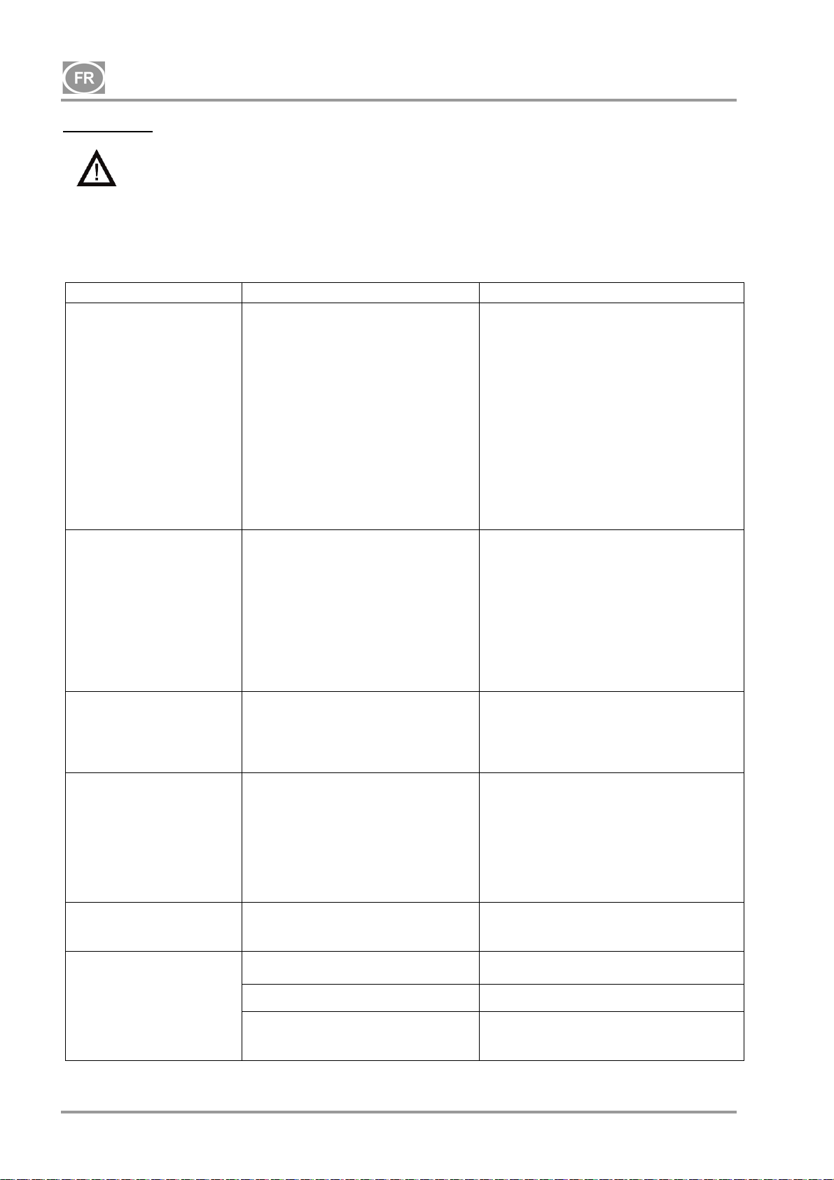
DK50-10
DÉPANNAGE
Mise en garde ! Avant toute intervention sur l’appareil, réduisez à zéro la pression dans le
réservoir d’air et débranchez l’appareil du secteur.
Pour une efficacité de séchage durablement élevée, il est nécessaire de garder l’ensemble de
l’appareil, et surtout le ventilateur propre ; nettoyez régulièrement la surface du ventilateur et les
ailettes de refroidissement du refroidisseur.
Les travaux de dépannage ne peuvent qu’être effectués par un technicien qualifié.
DYSFONCTIONNEMENTS CAUSE POSSIBLE SOLUTION
Le compresseur ne
démarre pas
Le compresseur est
régulièrement activé
Pression faible dans le
réservoir d’air (le
compresseur fonctionne
en continu)
Utilisation prolongée du
compresseur
Compresseur bruyant
(cognements, bruits de
métal)
Le sécheur ne sèche plus
(eau condensée dans le
réservoir) *
Pas de tension dans le pressostat Vérifiez la tension de la prise
Vérifiez le disjoncteur – si le commutateur
est sur la position « I »
Le conducteur de la borne est desserré –
desserrez-le
Vérifiez le cordon électrique – remplacez
le cordon défectueux
Défaillance de l’enroulement du
moteur, protection
de surcharge thermique
Condensateur en panne
Piston ou autres parties rotatives
grippés
Le pressostat ne fonctionne pas
Fuite d’air dans le système de
distribution d’air comprimé
Fuite observée sur le clapet
antiretour
Grand volume de liquide condensé
dans le récipient sous pression
Performance faible du compresseur
Forte consommation d’air par
l’appareil, fuite dans le système d’air
comprimé, production globale faible
Dysfonctionnement de l’agrégat
Dysfonctionnement du sécheur
Fuite d’air dans le système de
distribution d’air comprimé
Bague de piston usée
Filtre d’entrée obstrué
Électrovanne défectueuse
Roulement de piston, tige de piston,
roulement moteur endommagés
Ressort desserré ou fissuré
Le ventilateur de refroidissement ne
fonctionne pas
Sécheur endommagé Remplacez le sécheur
Remplacez le moteur ou rembobinez-le
Remplacez le condensateur
Remplacez les pièces endommagées
Vérifiez le fonctionnement du pressostat
Vérifiez le système de distribution d’air
comprimé – resserrez les joints non
hermétiques
Nettoyez l’électrovanne, remplacez les
joints d’étanchéité, remplacez
l’électrovanne
Vidangez le liquide condensé
Vérifiez le temps de remplissage du
réservoir d’air
Vérifiez le système de distribution d’air
comprimé – resserrez les joints non
hermétiques
Remplacez les bagues de piston usées
Remplacez le filtre usagé par un filtre
neuf
Réparez ou remplacez la soupape ou la
bobine
Remplacez le roulement endommagé
Remplacez le ressort endommagé
Remplacez-le
Vérifiez la source d’alimentation
Purge automatique des condensats
en panne – nettoyez/remplacez le
filtre
)* Après un dysfonctionnement du sécheur, nettoyez soigneusement les surfaces intérieures du réservoir
d’air et retirez tout le liquide condensé.
NP-DK50-1_08-2017-MD - 84 - 08/2017
Nettoyez/remplacez
Page 87

DK50-10
Afin de protéger les équipements raccordés contre tout dommage, contrôlez le point de rosée de
l’air s’échappant du réservoir d’air (cf. Chapitre 5 Données techniques) !
19. SERVICE DE RÉPARATION
Toutes les réparations, sous garantie ou après l’expiration de celle-ci, doivent être effectuées par le
fabricant, son représentant agréé ou par le personnel d’entretien agréé par le fournisseur.
Le fabricant se réserve le droit d’apporter des modifications à l’appareil sans préavis. Les
modifications apportées n’affecteront en aucun cas les propriétés fonctionnelles de l’appareil.
20. STOCKAGE
En cas de non-utilisation prolongée du compresseur, vidangez tout le condensat du réservoir d’air. Ensuite,
mettez le compresseur en marche pendant 10 secondes, en laissant la soupape de vidange ouverte (1)
(Fig. 11). Arrêtez le compresseur à l’aide du commutateur (3) du pressostat (2) (Fig. 9), puis fermez la
soupape de vidange et débranchez l’appareil du secteur.
21. MISE AU REBUT DE L’APPAREIL
Débranchez l’appareil du secteur.
Évacuez la pression d’air du réservoir en ouvrant la soupape de vidange (1) (Fig. 11).
Mettez l’appareil au rebut conformément aux réglementations environnementales en vigueur.
Confiez le tri et l’élimination des déchets à une entreprise spécialisée.
Les composants usés n'ont aucune incidence négative sur l'environnement.
08/2017 - 85 - NP-DK50-1_08-2017-MD
Page 88

DK50-10
CОДЕРЖАНИЕ
ВАЖНЫЕ СВЕДЕНИЯ ......................................................................................................................... 87
1. МАРКИРОВКА CE .................................................................................................................... 87
2. ПРЕДУПРЕЖДЕНИЯ ............................................................................................................... 87
3. ПРЕДУПРЕЖДЕНИЯ И СИМВОЛЫ ....................................................................................... 88
4. УСЛОВИЯ ХРАНЕНИЯ И ТРАНСПОРТИРОВКИ .................................................................. 89
5. ТЕХНИЧЕСКИЕ ХАРАКТЕРИСТИКИ ..................................................................................... 90
6. ОПИСАНИЕ ИЗДЕЛИЯ ........................................................................................................... 93
7. ПРИНЦИП ДЕЙСТВИЯ ИЗДЕЛИЯ ......................................................................................... 95
8. СХЕМА ПНЕВМАТИЧЕСКОГО ОБОРУДОВАНИЯ ............................................................... 99
ЭКСПЛУАТАЦИЯ ............................................................................................................................... 100
9. ВКЛЮЧЕНИЕ КОМПРЕССОРА ............................................................................................ 100
УСТАНОВКА ....................................................................................................................................... 101
10.УСЛОВИЯ ЭКСПЛУАТАЦИИ ................................................................................................ 101
11.РАЗМЕЩЕНИЕ КОМПРЕССОРА ......................................................................................... 102
12.ПНЕВМАТИЧЕСКИЕ СОЕДИНЕНИЯ ................................................................................... 103
13.ЭЛЕКТРИЧЕСКИЕ СОЕДИНЕНИЯ ...................................................................................... 103
14. СХЕМА ПОДКЛЮЧЕНИЯ ..................................................................................................... 104
15.ВВОД В ЭКСПЛУАТАЦИЮ ................................................................................................... 106
16.ВКЛЮЧЕНИЕ КОМПРЕССОРА ............................................................................................ 106
17.ВЫКЛЮЧЕНИЕ КОМПРЕССОРА ......................................................................................... 107
ТЕХНИЧЕСКОЕ ОБСЛУЖИВАНИЕ ................................................................................................. 107
18.ТЕХНИЧЕСКОЕ ОБСЛУЖИВАНИЕ ОБОРУДОВАНИЯ ...................................................... 107
УСТРАНЕНИЕ НЕИСПРАВНОСТЕЙ ................................................................................................ 112
19.РЕМОНТНЫЕ УСЛУГИ ......................................................................................................... 113
20.УСЛОВИЯ ХРАНЕНИЯ ......................................................................................................... 113
21.УТИЛИЗАЦИЯ УСТРОЙСТВА .............................................................................................. 113
ПРИЛОЖЕНИЕ ................................................................................................................................... 198
22. ОТЧЕТ ОБ УСТАНОВКЕ ...................................................................................................... 201
NP-DK50-1_08-2017-MD - 86 - 08/2017
Page 89

DK50-10
ВАЖНЫЕ СВЕДЕНИЯ
УВАЖАЕМЫЙ ПОЛЬЗОВАТЕЛЬ.
ПОЖАЛУЙСТА, ВНИМАТЕЛЬНО ПРОЧТИТЕ ДАННОЕ РУКОВОДСТВО ПО ЭКСПЛУАТАЦИИ ДЛЯ
ТОГО, ЧТОБЫ ОБЕСПЕЧИТЬ ОПТИМАЛЬНОЕ И ПРАВИЛЬНОЕ ФУНКЦИОНИРОВАНИЕ ВАШЕГО
МЕДИЦИНСКОГО ОБОРУДОВАНИЯ.
Изделие зарегистрировано и соответствует требованиям Федеральной Службы по надзору в сфере
здравоохранения и социального развития Российской Федерации.
Изделие соответствует системе сертификации ГОСТ Р Госстандарта России.
1. МАРКИРОВКА CE
Изделия, обозначенные знаком соответствия CE, соответствуют требованиям директив по
безопасности Европейского союза (93/42/EEC).
2. ПРЕДУПРЕЖДЕНИЯ
Данное изделие было спроектировано и произведено таким образом, чтобы не представлять
опасности для пользователя и окружающей среды при условии надлежащей эксплуатации. Помните
о перечисленных ниже предупреждениях. Это поможет
2.1. Общие предупреждения
свести к минимуму уровень риска.
Данное руководство пользователя поможет в правильной установке, эксплуатации и техническом
обслуживании изделия. Оно входит в комплект поставки изделия и должно всегда храниться
поблизости. В данном руководстве содержится информация, с которой необходимо ознакомиться
для надлежащей эксплуатации изделия.
Оригинальную упаковку необходимо сохранить на
случай возможного возврата оборудования.
Защиту устройства во время транспортировки гарантирует только оригинальная упаковка. Если
возникла необходимость вернуть изделие в течение гарантийного срока, производитель не несет
ответственность за повреждения, вызванные ненадлежащей упаковкой.
На неисправности, возникшие в результате применения аксессуаров или расходных материалов,
не указанных производителем, гарантия не распространяется.
Производитель
гарантирует безопасность, надежность и функционирование устройства только
при соблюдении таких условий:
— установку, перенастройку, исправления, расширение и ремонтные работы осуществляются
производителем или уполномоченной производителем сервисной службой;
— изделие используется в соответствии с данным руководством пользователя.
Руководство пользователя соответствует конфигурации изделия и отвечает стандартам
безопасности и техническим условиям, действующим на момент печати. Производитель
оставляет за собой все права на патентную защиту своих конфигурации, методов и названий.
Перевод руководства пользователя осуществляется с учетом всей доступной информации. В
случае сомнений требуется использовать версию на словацком языке.
2.2. Общие предупреждения относительно безопасности
Производитель спроектировал и произвел изделие таким образом, чтобы максимально сократить все
при условии правильной эксплуатации. Производитель считает своей обязанностью описать
риски
следующие меры по безопасности, чтобы можно было максимально сократить остальные риски.
Изделие необходимо эксплуатировать в соответствии со всеми региональными стандартами и
нормами. Оператор и пользователь несут ответственность за соблюдение всех соответствующих
норм с целью обеспечения безопасной эксплуатации.
Только использование
оригинальных частей гарантирует безопасность обслуживающего
персонала и бесперебойную работу самого изделия. Разрешается применять только
приспособления и детали, указанные в технической документации или непосредственно
утвержденные производителем.
Перед каждым использованием оператор должен убедиться, что оборудование функционирует
надлежащим образом и безопасно для эксплуатации.
08/2017 - 87 - NP-DK50-1_08-2017-MD
Page 90
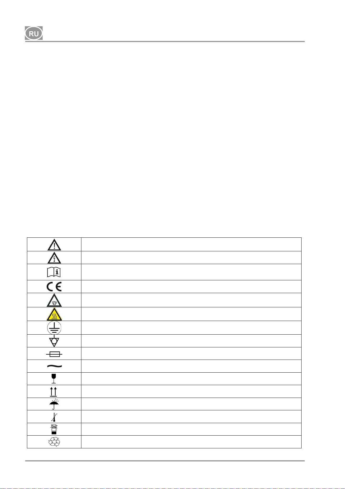
DK50-10
Пользователь должен абсолютно понимать принцип работы устройства.
Изделие нельзя использовать во взрывоопасных средах.
Пользователь обязан немедленно уведомить поставщика в случае возникновения каких-либо
проблем во время эксплуатации оборудования.
2.3. Предупреждения по безопасности работы электрической системы
Оборудование можно подключать только к надлежащим образом установленной и заземленной
розетке.
Перед подключением изделия к сети необходимо проверить, соответствуют ли указанные на
устройстве напряжение и частота соответствующим значениям электрической сети.
Перед эксплуатацией проверьте подключенную систему подачи сжатого воздуха и электрическую
цепь на предмет наличия повреждений. В случае повреждения пневматических и электрических
проводников немедленно замените их.
При возникновении опасной ситуации
изделие от электрической сети (вытащите сетевой шнур из розетки).
В процессе технического обслуживания и ремонта убедитесь в следующем:
— сетевой штепсель должен быть отключен от розетки;
— линии подачи сжатого воздуха и воздухосборник должны быть не под давлением.
Установку изделия может осуществлять только квалифицированный
3. ПРЕДУПРЕЖДЕНИЯ И СИМВОЛЫ
или технической неисправности немедленно отсоедините
технический специалист.
В руководстве пользователя, а также на оборудовании и упаковке к нему для обозначения важных
сведений используются перечисленные ниже отметки и символы.
Сведения, инструкции или предупреждения во избежание вреда здоровью и
материального ущерба
Осторожно! Опасное электрическое напряжение
Прочтите руководство пользователя!
Обозначение соответствия требованиям CE
Осторожно! Горячая поверхность
Компрессор управляется дистанционно и может запускаться без
предупреждения
Заземляющее соединение
Клемма заземления
Предохранитель
Переменный ток
Маркировка на упаковке — ХРУПКИЙ ПРЕДМЕТ
Маркировка на упаковке — ЭТОЙ СТОРОНОЙ ВВЕРХ
Маркировка на упаковке — БЕРЕЧЬ ОТ ВЛАГИ
Маркировка на упаковке — ТЕМПЕРАТУРНЫЕ ОГРАНИЧЕНИЯ
Маркировка на упаковке — ШТАБЕЛИРОВАНИЕ ОГРАНИЧЕНО
Маркировка на упаковке — ПРИГОДНО ДЛЯ ВТОРИЧНОЙ ПЕРЕРАБОТКИ
NP-DK50-1_08-2017-MD - 88 - 08/2017
Page 91
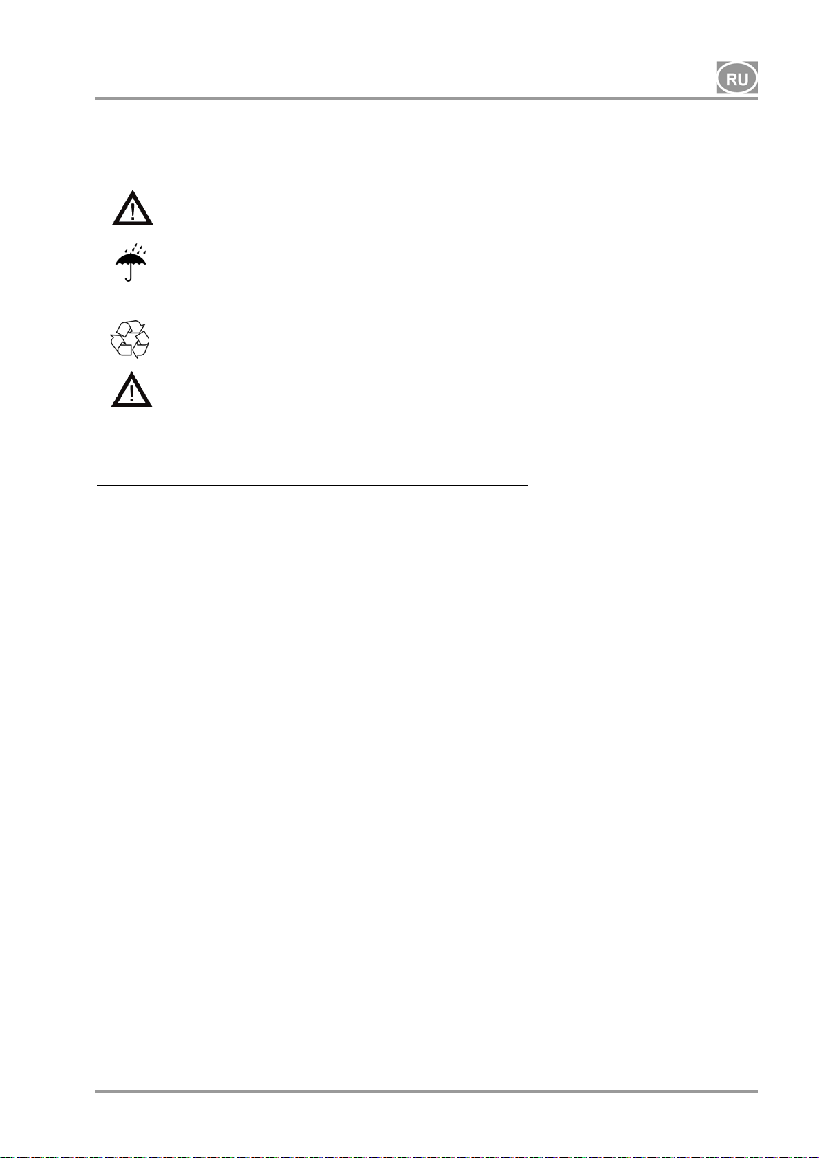
DK50-10
4. УСЛОВИЯ ХРАНЕНИЯ И ТРАНСПОРТИРОВКИ
Компрессор перевозится в картонной коробке, которая защищает устройство от повреждений при
транспортировке.
Осторожно! Всегда используйте для транспортировки оригинальную упаковку и
закрепляйте компрессор в вертикальном положении.
Во время транспортировки и хранения защищайте компрессор от влажности и
экстремальных температур. Компрессоры в оригинальной упаковке можно хранить в
Условия окружающей среды при хранении и транспортировке
теплых
веществ.
По возможности сохраните упаковочный материал. В противном случае утилизируйте его
экологически безопасным способом или используйте повторно, если это возможно.
Осторожно! Перед перемещением или транспортировкой компрессора сбросьте
давление воздуха с воздухосборника и напорных шлангов, а также слейте водяной
конденсат.
, сухих и незапыленных помещениях. Не допускается хранение вблизи химических
Изделия можно хранить и перевозить только в транспортных средствах, не содержащих остатков
летучих химических веществ при указанных ниже условиях.
Температура: от –25 °С до +55 °С (24 ч при температуре до +70 °C)
Относительная влажность: 10–90 % (при отсутствии конденсата)
08/2017 - 89 - NP-DK50-1_08-2017-MD
Page 92
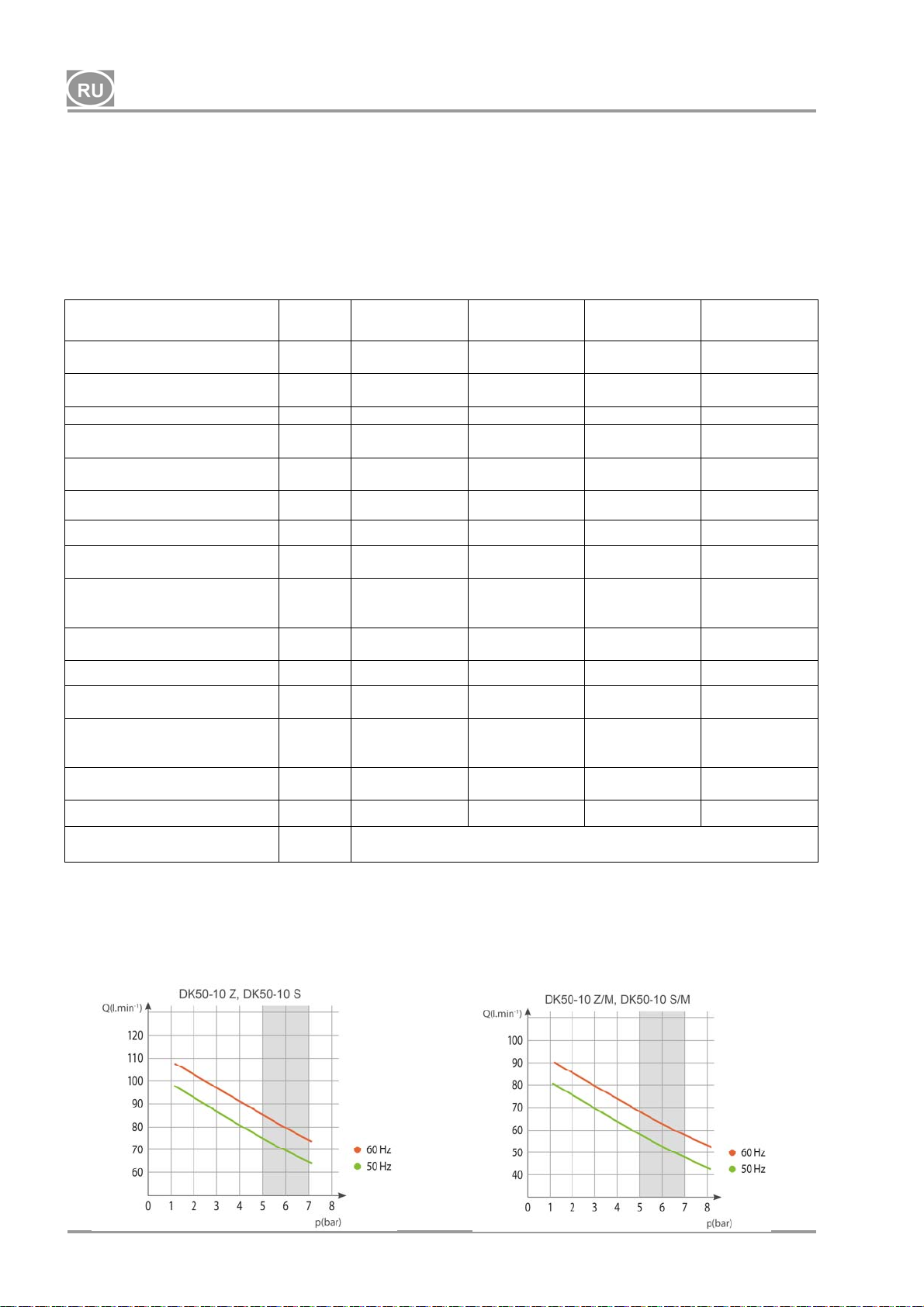
DK50-10
5. ТЕХНИЧЕСКИЕ ХАРАКТЕРИСТИКИ
Компрессоры спроектированы для эксплуатации в сухих и вентилируемых помещениях при
указанных ниже условиях.
Температура: +5–40 °C
Макс. относительная влажность: 70 %
Макс. абсолютная влажность: 15 г/м
Таблица 1
3
5–7 бар
Номинальное напряжение и
частота (*)
Значение на выходе
при 5 бар
Рабочее давление (**) бар 5,0 – 7,0 5,0 – 7,0 5,0 – 7,0 5,0 – 7,0
Значение на выходе с KJF-1
при 5 бар
Макс. ток А
Мощность двигателя кВт 0,55 0,55 0,55 0,55
Объем воздухосборника л 10 10 10 10
Качество воздуха
(фильтрация)
Максимальное рабочее
давление предохранительного
клапана
Уровень шума при 5 бар LpfA [дБ]
Рабочий режим 100% - S 1 100% - S 1 100% - S 1 100% - S 1
Степень осушения - PDP при
7 бар
Время наполнения
воздухосборника при
давлении от 0 до 6 бар
Размеры (без упаковки)
(Ш x Г x В)
Вес нетто кг
Конфигурация в соответствии
со стандартом EN 60601-1
В / Гц
л/мин
л/мин
мкм
бар 8,0 8,0 8,0 8,0
- -
с
мм 485x350x553 580x440x655 544x350x553 649x440x655
Тип B, класс I.
DK50-10 Z DK50-10 S DK50-10 Z/M
-1
-1
230 / 50/60
115 / 60
75 / 85
85
75 / 85
85
3,8 / 4,8
9,5
- - 0,3 0,3
65 / 66,5
66,5
50 / 44
44
***) 53 (***)
38 (
230 / 50/60
115 / 60
75 / 85
85
75 / 85
85
3,8 / 4,8
9,5
49,5 / 51
51
50 / 44
44
230 / 50/60
115 / 60
58 / 68
4,1 / 5,1
67 / 68,5
+3°C
70/60
DK50-10 S/M
230 / 50/60
115 / 60
58 / 68
68
- -
10
68,5
60
44
68
4,1 / 5,1
10
51,5 / 53
53
+3°C
70/60
60
61
Примечания.
(*) При заказе указывайте модель компрессора
(**) Диапазон давления (посоветуйтесь с подрядчиком)
(***) Добавьте 3 кг к весу компрессора за счет модуля KJF1
(****) Можно также задать другое допустимое рабочее давление предохранительного клапана,
например 9 бар / значение будет указано в заказе.
NP-DK50-1_08-2017-MD - 90 - 08/2017
Page 93
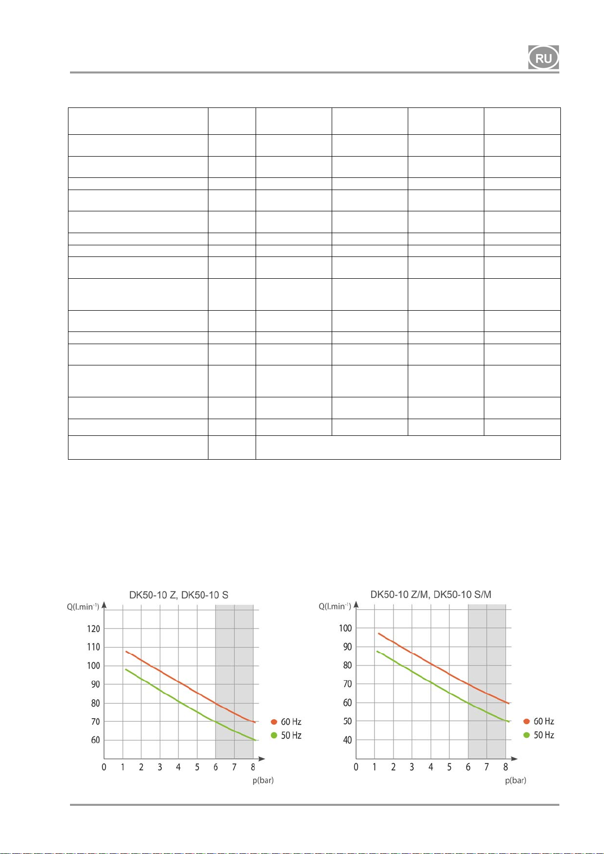
DK50-10
Табл. 2
6–8 бар
Номинальное напряжение и
частота ( *)
Значение на выходе
при 6 бар
Рабочее давление (**) бар 6,0 – 8,0 6,0 – 8,0 6,0 – 8,0 6,0 – 8,0
Значение на выходе с KJF-1
при 6 бар
Макс. ток А
Мощность двигателя кВт 0,55 0,55 0,55 0,55
Объем воздухосборника 10 10 10 10
Качество воздуха
(фильтрация)
Максимальное рабочее
давление предохранительного
клапана
Уровень шума при 5 бар LpfA [дБ]
Рабочий режим
Степень осушения - PDP при
7 бар
Время наполнения
воздухосборника при
давлении от 0 до 7 бар
Размеры (без упаковки)
(Ш x Г x В)
Вес нетто кг
Конфигурация в соответствии
со стандартом EN 60601-1
В / Гц
-1
л/мин
-1
л/мин
мкм
бар 12,0 12,0 12,0 12,0
- -
с
мм 485x350x553 580x440x655 544x350x553 649x440x655
DK50-10 Z DK50-10 S DK50-10 Z/M
230 / 50/60
115 / 60
70 / 80
80
70 / 80
80
3,9 / 4,9
9,8
- - 0,3 0,3
65 / 66,5
66,5
100% - S 1 100% - S 1 100% - S 1 100% - S 1
60 / 51
51
38 (***) 53 (***)
230 / 50/60
115 / 60
70 / 80
80
70 / 80
80
3,9 / 4,9
9,8
49,5 / 51
51
60/51
51
Тип B, класс I.
230 / 50/60
115 / 60
60 / 70
70
- -
4,1 / 5,1
10,2
67 / 68,5
68,5
+3°C
72/61
61
44
DK50-10 S/M
70
230 / 50/60
115 / 60
60 / 70
4,1 / 5,1
10,2
51,5 / 53
53
+3°C
72/61
61
61
Примечания.
(*) При заказе указывайте модель компрессора
(**) Диапазон давления (посоветуйтесь с подрядчиком)
(***) Добавьте 3 кг к весу компрессора за счет модуля KJF1
(****) Можно также задать другое допустимое рабочее давление предохранительного клапана,
например 9 бар / значение будет указано в заказе.
08/2017 - 91 - NP-DK50-1_08-2017-MD
Page 94
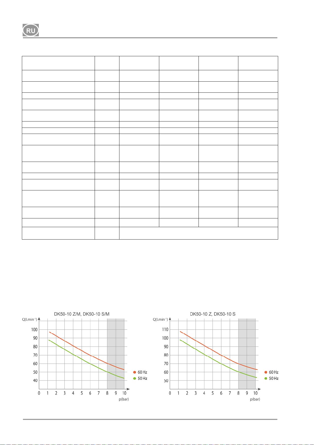
DK50-10
Табл. 3
8–10 бар
Номинальное напряжение и
частота ( * )
Значение на выходе
при 8 бар
Рабочее давление (**) бар 8,0 – 10,0 8,0 – 10,0 8,0 – 10,0 8,0 – 10,0
Значение на выходе с KJF-1
при 8 бар
Макс. ток А
Мощность двигателя кВт 0,55 0,55 0,55 0,55
Объем воздухосборника 10 10 10 10
Качество воздуха
(фильтрация)
Максимальное рабочее
давление предохранительного
клапана
Уровень шума при 5 бар LpfA [дБ]
Рабочий режим
Степень осушения - PDP при
7 бар
Время наполнения
воздухосборника при
давлении от 0 до 9 бар
Размеры (без упаковки)
(Ш x Г x В)
Вес нетто кг
Конфигурация в соответствии
со стандартом EN 60601-1
В / Гц
-1
л/мин
-1
л/мин
мкм
бар 12,0 12,0 12,0 12,0
- -
с
мм 485x350x553 580x440x655 544x350x553 649x440x655
DK50-10 Z DK50-10 S DK50-10 Z/M
230 / 50/60
115 / 60
60 / 70
70
60 / 70
70
4,1 / 5,1
10,2
- - 0,3 0,3
65 / 66,5
66,5
100% - S 1 100% - S 1 100% - S 1 100% - S 1
85/75
75
38 (***) 53 (***)
230 / 50/60
115 / 60
60 / 70
70
60 / 70
70
4,1 / 5,1
10,2
49,5 / 51
51
85/75
75
Тип B, класс I.
230 / 50/60
115 / 60
50 / 60
60
- -
4,3 / 5,3
10,5
67 / 68,5
68,5
+3°C
96/82
82
44
DK50-10 S/M
230 / 50/60
115 / 60
50 / 60
60
4,4 / 5,4
10,5
51,5 / 53
53
+3°C
96/82
82
61
Примечания.
(*) При заказе указывайте модель компрессора
(**) Диапазон давления (посоветуйтесь с подрядчиком)
(***) Добавьте 3 кг к весу компрессора за счет модуля KJF1
(****) Можно также задать другое допустимое рабочее давление предохранительного клапана,
например 9 бар / значение будет указано в заказе.
NP-DK50-1_08-2017-MD - 92 - 08/2017
Page 95
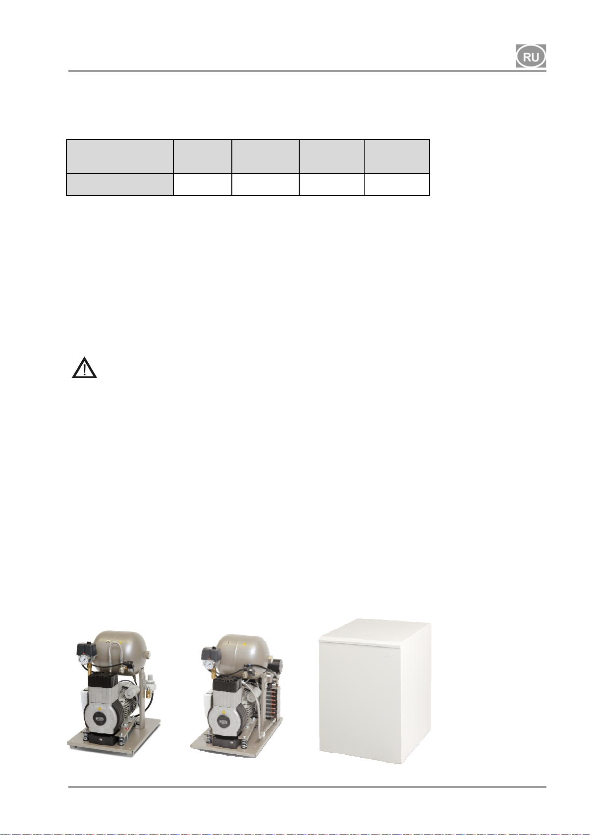
DK50-10
5.1. Поправки потребляемого объема сжатого воздуха за единицу времени (ПОСВ)
вследствие подъема
Таблица поправок ПОСВ
Подъем [м над
уровнем моря]
ПОСВ [л/мин] ПОСВ x 1 ПОСВ x 0,8 ПОСВ x 0,71 ПОСВ x 0,60
Выход (ПОСВ) с поправкой на условия
Подъем: 0 метров над уровнем моря Температура: 20 °C
Атмосферное давление: 101 325 Па Относительная влажность: 0 %
6. ОПИСАНИЕ ИЗДЕЛИЯ
6.1. Различные модели и их применение
0–1500 1501–2500 2501–3500 3501–4500
Медицинские компрессоры являются источником чистого, безмасляного сжатого воздуха
предназначенного для присоединения к зубоврачебным устройствам и оборудованиям, в которых
характеристики и свойства сжатого воздуха соответствуют указанному целевому назначению.
Нагнетаемый компрессором сжатый воздух подходит для использования в аппаратах
ИВЛ только при условии последующей его фильтрации
Любая эксплуатация оборудования в целях, отличных от указанных здесь, считается ненадлежащим
его использованием. Производитель
таким ненадлежащим использованием.
6.2. Описание
Модели компрессоров имеют описанное ниже предназначение.
Дентальные компрессоры DK50 Z и DK50-10 Z - с основанием, которое позволяет
разместить компрессор самостоятельно в помещении клиники.
Дентальные компрессоры DK50 Z/K и DK50-10 Z/K - с основанием и с конденсационным и
фильтрационным элементом (KJF1).
Дентальные компрессоры DK50-10 Z/M - с основанием
Дентальные компрессоры DK50 S и DK50-10 S - в компактных шкафчиках с активным
поглощением шума, подходят для размещения в медицинском кабинете.
Дентальные компрессоры DK50 S/K и DK50-10 S/K - в компактных шкафчиках и с
конденсационным а фильтрационным элементом (KJF1).
Дентальные компрессоры DK50-10 S/M - в компактных шкафчиках и с мембранным осушителем.
DK50-10 Z
08/2017 - 93 - NP-DK50-1_08-2017-MD
DK50-10 Z/M
не несет ответственности за повреждения и травмы, вызванные
и с мембранным осушителем.
DK50-10 S
DK50-10 S/M
,
Page 96
DK50-10
6.3. Принадлежности
Принадлежности, не входящие в стандартный заказ, необходимо приобретать дополнительно.
6.3.1 Система автоматического слива конденсата
Система автоматического слива конденсата (AOK) автоматически сливает конденсат из
воздухосборника компрессора с установленной периодичностью. Система слива конденсата (AOK)
рассчитана на модели компрессоров без осушителей.
6.3.2 Комплект фильтров
Если указано, компрессоры можно оснастить комплектом фильтров на
Комплект фильтров можно оснастить регулятором давления. Комплекты фильтров — это
принадлежности, предназначенные для всех перечисленных выше компрессоров.
ПРИМЕЧАНИЕ. Если требуется более высокий уровень фильтрации воздуха, данные технические
характеристики необходимо согласовать с поставщиком и четко указать в заказе.
Степень фильтрации
КОМПЛЕКТ
ФИЛЬТРОВ
6.3.3 Конденсационный и фильтровальный элемент (KJF)
Компрессор может поставляться с конденсационным и фильтровальным элементами (KJF-1 или
KJFR-1). Элементы KJF-1 или KJFR-1 обеспечивают охлаждение сжатого воздуха из ресивера в
охладителе, а также собирают конденсат в фильтре, автоматически выделяя его из контура сжатого
воздуха. Сжатый воздух в это время фильтруется.
Конденсационный и
фильтровальный
элемент
KJF-1
KJFR-1 Да 450001011-002
—
5 мкм 604013233-000
0,3 мкм
0,01 мкм 604013235-000
Степень
фильтрации
Регулятор давления Артикул комплекта
Да
Нет
Регулятор
давления
Нет 450001011-001
5µm
604013245-000
604013234-000
Артикул комплекта
выходе сжатого воздуха.
NP-DK50-1_08-2017-MD - 94 - 08/2017
Page 97
DK50-10
7. ПРИНЦИП ДЕЙСТВИЯ ИЗДЕЛИЯ
Компрессор (рис. 1)
Узел компрессора (1) всасывает атмосферный воздух через фильтр на входе (8) и нагнетает его
через обратный клапан (3) в воздухосборник (2), из которого устройство всасывает сжатый воздух.
Если давление в воздухосборнике понижается до уровня срабатывания, переключатель давления (4)
включает компрессор, и последний подает сжатый воздух в воздухосборник до уровня
отключения, при котором компрессор отключается. После отключения узла компрессора давление в
напорном шланге стравливается через электромагнитный выпускной клапан (13).
Предохранительный клапан (5) предотвращает превышение максимально допустимого уровня
давления в воздухосборнике. Конденсат из воздухосборника сливается через спускной клапан (7).
Сжатый, отфильтрованный и обезмасленный воздух сохраняется в воздухосборнике и готов к
использованию.
Конденсат из воздухосборника
Компрессор с мембранным осушителем (рис. 3)
Узел компрессора (1) всасывает атмосферный воздух через фильтр на входе (8) и нагнетает его в
охладитель (14), после чего он через фильтр (15) поступает в осушитель (9). Оттуда сухой чистый
воздух через обратный клапан (3) поступает в воздухосборник (2). Часть воздуха с улавливаемой
влагой слабым потоком подается
автоматически через электромагнитный клапан (16) в резервуар. Осушитель обеспечивает
непрерывное осушение сжатого воздуха. Когда процесс осушения зафиксирован, конденсат из
воздухосборника сливается через спускной клапан (7). Сжатый, отфильтрованный и обезмасленный
воздух сохраняется в воздухосборнике и готов к использованию.
Для компрессора с осушителем не требуется оператор.
сливать конденсат.
необходимо сливать регулярно (см. раздел 18).
в обход осушителя (9). Конденсат из фильтра регулярно сливается
Из напорного резервуара не требуется
давления
Компрессор с конденсационным и фильтровальным блоком (рис. 2)
Узел компрессора (1) всасывает атмосферный воздух через фильтр на входе (8) и нагнетает его
через обратный клапан (3) в воздухосборник (2). Из воздухосборника сжатый воздух поступает в
охладитель (10), где он охлаждается. Влага улавливается фильтром (11) и автоматически оседает в
виде конденсата
использованию.
Конденсат из воздухосборника необходимо сливать регулярно (см. раздел 18).
Корпус компрессора
Звукоизоляционный корпус имеет небольшой размер и обеспечивает достаточную циркуляцию
охлаждающего воздуха. Конструкция позволяет устанавливать его в офисных помещениях, где он
гармонично вписывается в интерьер. Вентилятор, расположенный под узлом компрессора,
обеспечивает
срабатывания температурного переключателя при температуре выше 40 °C.
Убедитесь, что нет препятствий для свободной циркуляции воздуха вокруг
компрессора и под ним. Запрещается перекрывать выход горячего воздуха в
верхней задней части корпуса.
Устанавливая компрессор на мягкую поверхность (например, ковер), необходимо
создать щель
подложить под основание твердые прокладки, для обеспечения хорошего
охлаждения компрессора.
Модель компрессора с давлением 10 бар оборудована часометром (рис. 4)
(12) в резервуаре. Сжатый, отфильтрованный и обезмасленный воздух готов к
достаточное его охлаждение и запускается от двигателя компрессора или в случае
между основанием и полом или шкафчиком и полом, например
08/2017 - 95 - NP-DK50-1_08-2017-MD
Page 98
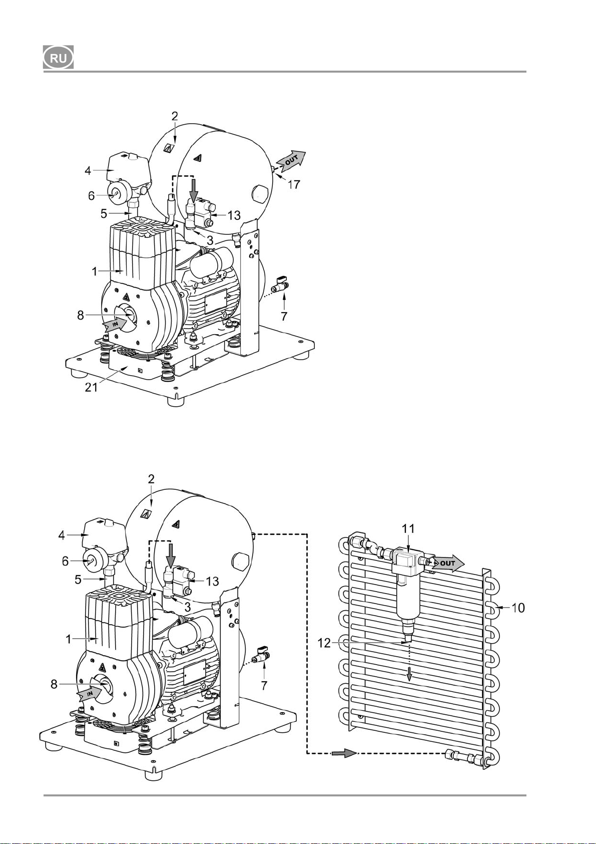
DK50-10
Рис. 1. DK50-10 Z (компрессор)
Описание рисунков 1–4
1. Узел компрессора
2. Воздухосборник
3. Обратный клапан
4. Переключатель давления
5. Предохранительный клапан
6. Манометр
7. Клапан слива
8. Входной фильтр
9. Осушитель
10. Трубный охладитель
11. Фильтр
12. Выпуск конденсата
13. Электромагнитный клапан
14. Охладитель осушителя
15. Фильтр
16. Клапан с таймером
17. Выпускной воздуховод
сжатого воздуха
18. Разъединитель
19. Резервуар
20. Магнитный кронштейн
21. Вентилятор
22.
Переключатель
23. Cчетчик часов
24. Соединитель
25. Вентилятор для обдува корпуса
Рис. 2. DK50-10 Z/K (компрессор с конденсационным и фильтровальным блоком KJF1)
NP-DK50-1_08-2017-MD - 96 - 08/2017
Page 99
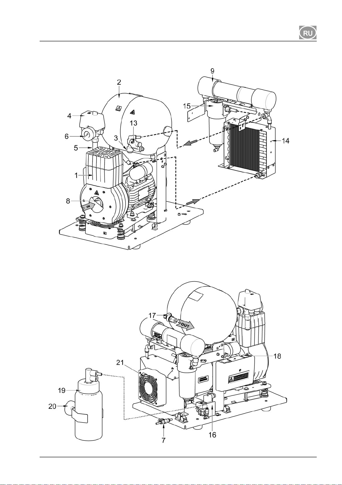
DK50-10
Рис. 3. DK50-10 Z/M (компрессор с осушителем)
08/2017 - 97 - NP-DK50-1_08-2017-MD
Page 100
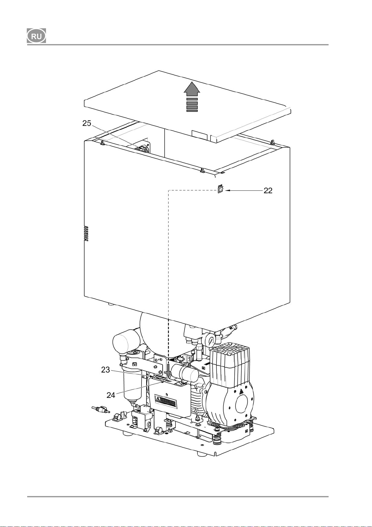
DK50-10
Рис. 4. Компрессор DK50-10 S/M (10 бар)
NP-DK50-1_08-2017-MD - 98 - 08/2017
 Loading...