

Page 1
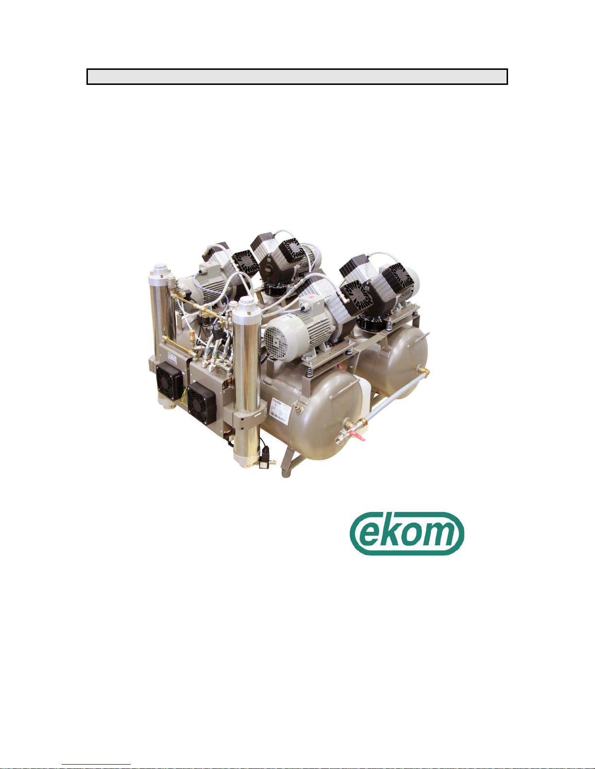
OIL-FREE COMPRESSOR DUPLEX DK50 4x2V/M
OPERATION MANUAL
EKOM spol. s r.o.
Priemyselná 5031/18
921 01 Piešť any
Slovak republic
Tel.:+421 33 7967 255
Fax.:+421 33 7967 223
E-mail: [email protected]
Page 2

OPERATION MANUAL DK 50 4x2V/M
NP-DK50 4x2V-M-EN-16_11-2015 11/2015
2
CONTENTS
1. WARNINGS ................................................................................................................................ 3
1.1. General warnings ................................................................................................................... 3
1.2. General safety warnings ....................................................................................................... 3
1.3. Safety warnings regarding the protection against electric current ......................................... 3
2. PRODUCT INFORMATION ....................................................................................................... 5
2.1. Purpose and use .................................................................................................................... 5
2.2. Product description ................................................................................................................ 5
3. TECHNICAL DATA.................................................................................................................... 6
4. RANGE OF DELIVERY ......................................... CHYBA! ZÁLOŽKA NIE JE DEFINOVANÁ.
5. INSTALLATION AND ASSEMBLY ........................................................................................... 6
6. PUTTING THE PRODUCT INTO OPERATION ......................................................................... 7
7. PRODUCT MAINTENANCE ...................................................................................................... 8
7.1. Replacement of the input filter and prefilter ........................................................................... 8
7.2. Replacement / cleaning of filter in air dryer ........................................................................... 8
7.3. Check of safety valve ............................................................................................................. 9
7.4. Replacement of filter element in filter ..................................................................................... 9
7.5. Regulation output pressure air regulator ............................................................................... 9
7.6. Intervals of maintenance ...................................................................................................... 10
8. INFORMATION ON REPAIR SERVICE .................................................................................. 11
9. TROUBLESHOOTING AND SOLVING COMMON PROBLEMS ........................................... 11
10. ENCLOSURES ......................................................................................................................... 13
11. PNEUMATIC SCHEMA ........................................................................................................... 14
12. LIST OF COMPONENTS ......................................................................................................... 15
Page 3

OPERATION MANUAL DK 50 4x2V/M
NP-DK50 4x2V-M-EN-16_11-2015 11/2015
3
1. WARNINGS
1.1. General warnings
The installation, operation and maintenance manual is an integral part of the appliance. It is
necessary to always keep this document close to the appliance. Strict observance of this manual
is a prerequisite for the correct operation of the appliance.
The safety of operating personnel and failure-free operation of the appliance are ensured only
when using the original components of the appliance. Only accessories specified in the technical
documentation or approved by the manufacturer must be used.
When used with non authorized accessories or consumable material, the manufacturer cannot
assume responsibility for the safe operation and functionality of the device.
The Guarantee does not cover damages that originate due to the use of non authorized
accessories or consumable material other than those recommended by the manufacturer.
The manufacturer assumes responsibility regarding safety, reliability and function only if
- The installation, calibration, amendments, extensions and repairs are made by the
manufacturer or his representative or a service organization authorized by the
manufacturer,
- The appliance is used in accordance with the installation, operation and maintenance
manual.
1.2. General safety warnings
The manufacturer developed and constructed the appliance so that damage would not occur
when the appliance is used for its intended purpose. The manufacturer considers it his obligation
to describe the following safety measures in order to avoid further damages.
When operating the appliance, it is necessary to observe laws and regional regulations valid in the
place of usage. In order to ensure safe course of works, the operator and user are responsible for
the observation of regulations.
The original packaging should be kept for the possible return of the unit. Only original packaging
guarantees an optimal protection of the appliance during transportation. If it would be necessary to
return the appliance during warranty period, the manufacturer is not responsible for damages
caused by incorrect packing.
It is necessary that the user ensures the appliance is safe to use prior to usage.
The user must familiarize himself with the correct operation of appliance.
If an undesirable event occurs in the operation of appliance, the user is obliged to immediately
inform his supplier to this event.
This product is not intended for use in areas with the risk of explosion.
1.3. Safety warnings regarding the protection against electric current
The appliance must only be connected to an appropriate power source that has correct grounding.
Prior the connecting the compressor, verify whether the mains voltage and frequency specified on
the apparatus are in accordance with the local supply.
Prior to putting into operation, check for possible damages on the appliance and the air
connectors. Damaged cables and sockets/plugs must be replaced immediately.
In the case of a dangerous situation or a technical failure, immediately disconnect the appliance
from mains supply.
During all repairs and maintenance:
- ensure that the mains plug is removed from the power socket
- pressure pipes must be air vented
- pressure must be released from pressure tank.
This appliance can only be installed only by a qualified expert.
Page 4
OPERATION MANUAL DK 50 4x2V/M
NP-DK50 4x2V-M-EN-16_11-2015 11/2015
4
2. ALERT NOTICES AND SYMBOLS
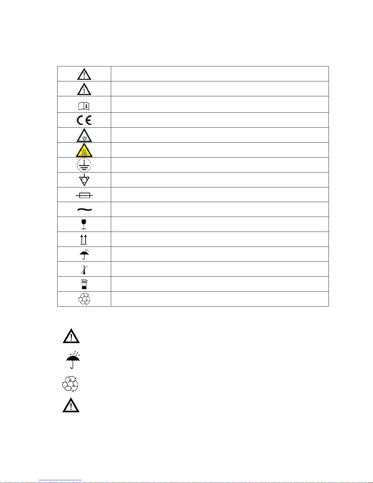
In the Installation, Operation and Maintenance Manual and on packaging and product, the following
labels or symbols are used for important information:
Information, instructions and cautions for the prevention of damage to health or
materials
Caution! Dangerous electrical voltage
Read the user manual!
CE mark of compliance
Compressor is remote-controlled and may start without warning
Caution! Hot surface
Earth (ground) connection
Terminal for ground connection
Fuse
Alternating current
Handling mark on package – FRAGILE
Handling mark on package – THIS SIDE UP
Handling mark on package – KEEP DRY
Handling mark on package – TEMPERATURE LIMITATIONS
Handling mark on package – LIMITED STACKING
Mark on package – RECYCLABLE MATERIAL
3. STORAGE AND TRANSPORT
The compressor is shipped in cardboard that protects the appliance from damage during transport.
Caution! For transport, always use the original packaging and secure the
compressor in the upright position.
Protect the compressor from humidity and extreme temperatures during transport and
storage. A compressor in its original packaging can be stored in a warm, dry and dust-free
area. Do not store near any chemical substances.
Keep packaging material if possible. If not, please dispose of the packaging material in an
environmentally friendly way and recycle if possible.
Caution! Before moving or transporting the compressor, release all the air pressure
from the tank and hoses and drain the condensed water.
Page 5
OPERATION MANUAL DK 50 4x2V/M
NP-DK50 4x2V-M-EN-16_11-2015 11/2015
5
4. PRODUCT INFORMATION
4.1. Purpose and use
Oil-free compressor DK50 4x2V/M - DUPLEX with dryer MONZUN serves as the source of dry, clean,
oil-free compressed air for driving pneumatic appliances and equipment. With its performance,
operational pressures, but also economic operation, it is suitable for the use in large dental
laboratories, dental clinics, with another auxiliary device even as the source of compressed air for
driving devices for support of respiration, for departments of hospitals, as well as in further areas of
medical practice, in food industry, and everywhere clean and dry compressed air is necessary and
where compressor with its version, performance and operational pressure meets the given
requirements.
The device is construed for environment of interior spaces, where temperature of air is within the
scope of +5°C to +35°C, relative humidity does not exceed 80% and absolute humidity of air does not
exceed 15 g/m
3
.
Oil-free compressor DK 50 4x2V - DUPLEX (without dryer) serves as the source of oil-free
compressed air for driving pneumatic appliances and equipment.
4.2. Product description
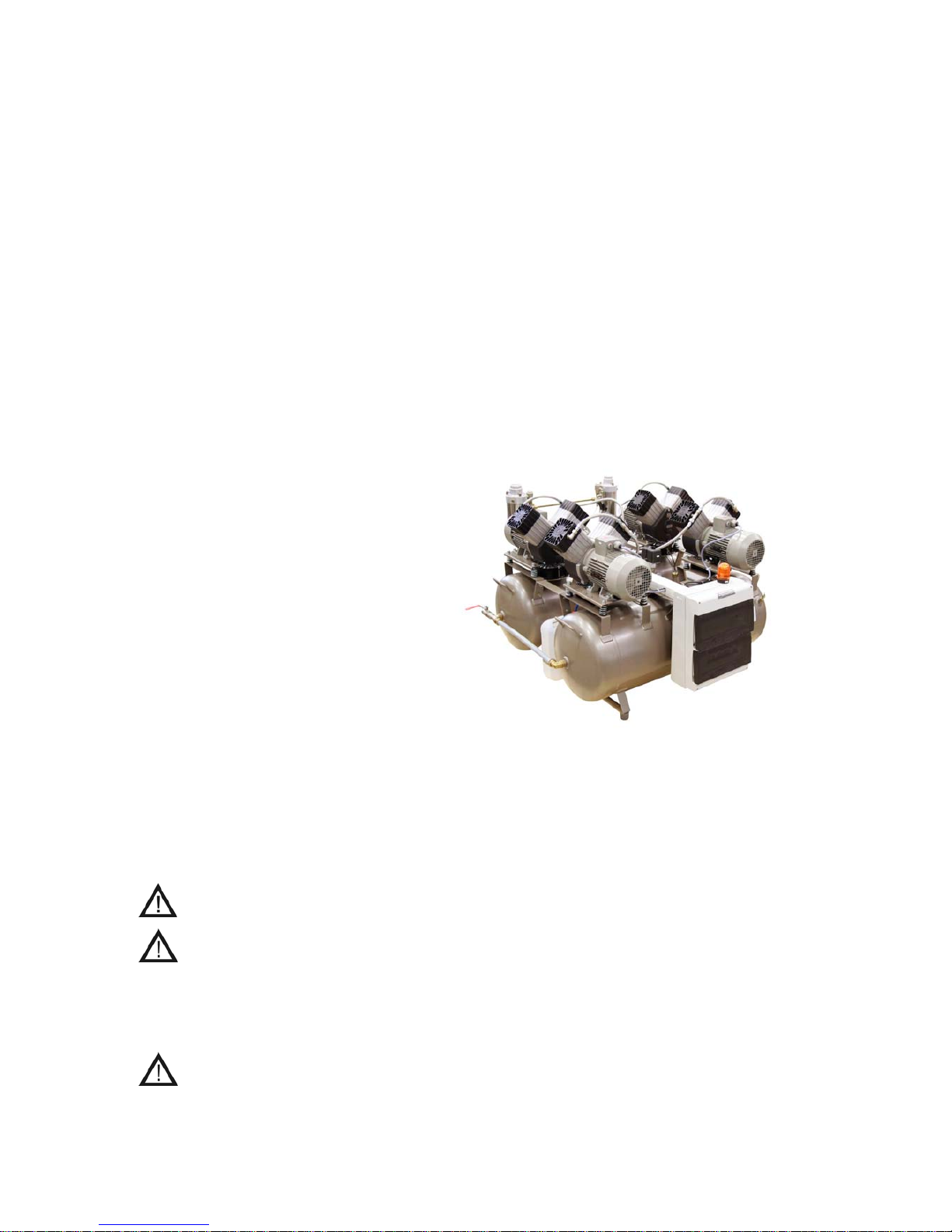
The assembly consists of four oil-free,
piston, two-cylinder compressors driven
by three-phase electric motors located
on two air chambers with fittings for
input of compressed air, check valves,
pressure meter, safety valves, pressure
switch and sludge valves. Air chambers
are mechanically connected via
stabilizing consoles and at both
rounded sides of air chambers are
connected by direct pipes. The output
of compressed air from entire unit is
created by ball valve with internal
G3/4“ thread.
Valid for DK50 4x2V/M
There is mechanically fixed air dryer
MONZUN with cooling unit.
New type of the safety valve (PRV) is
included into the pneumatic distribution
between the compressor aggregates
and the dryer.
The safety valve for the air (PRV) is intended for the prevention of pressure increase in the pressure
circuit of the compressor over the permissible value, providing for the protection of individual
pneumatic parts, above all for the compressor aggregates against an adverse influence of inadequate
pressures. The opening pressure of PRV is set to 11 bar.
It is forbidden to deliberately reset the opening pressure on the safety valve; the
resetting should always be agreed on with the manufacturer!
The outlets on the safety valve may neither be closed, nor the pressure air exit
therethrough limited.
When the pressure in the pressure circuit of the compressor increases to the value of set opening
pressure, the PRV automatically starts letting the air from the system through. When the pressure
drops, the PRV will close.
The pressure increase in the pressure circuit can only occur due to the increase of
flow resistances of the pneumatic distributions or in case of the dryer failure (e.g.
non-functional solenoid valves, increased flow resistance of a drying material and
similar) and therefore if a repeated opening of the safety valve occurs, it is
unavoidable to check the dryer function, possibly to repair it
!
Page 6
OPERATION MANUAL DK 50 4x2V/M
NP-DK50 4x2V-M-EN-16_11-2015 11/2015
6
5. TECHNICAL DATA
Compressor performance: 560 l.min
-1
at overpressure 0,5MPa.
Compressor performance with dryer: 480 l.min
-1
at overpressure 0,5MPa.
Rated voltage / frequency: 3 x 400 V (10%) / 50 Hz
Rated current: 14,5 A
Air chamber capacity: 220 lit.
Working pressure of compressor: 0,6 MPa 0,8 MPa.
Safety valve - opening pressure: 1,2 MPa.
Noise level(dist. 1m, at 480 l.min
-1
a 0,5 Mpa): 73 dB [A]
Weight of device: 240 kg
Dimensions and shape: according to picture
Operation mode: permanent operation – S1
Version: appliance of B type, class I.
(podľa STN EN 60 601-1)
Drying grade of comp.: (only for DK50 4x2V/M) atmospheric dew point - 20
o
C
Advised capacity for exchange of cooling air: 2 297 [m3/hod]
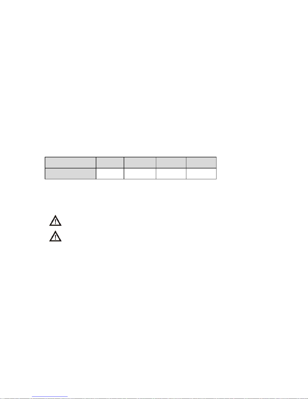
FAD efficiency correction for differences in elevation
FADcorrectiontable
FAD efficiency refers to conditions at an elevation of 0 mamsl: Temperature: 20°C
Atmospheric pressure: 101325 Pa
Relative humidity: 0%
6. INSTALLATION AND ASSEMBLY
Remove fixing elements after unpacking the compressor!
The installation can be performed only by an qualified expert trained by producer
with corresponding electrotechnical qualification!
Air chambers with compressors and dryer after unpacking and unscrewing of screws from transport
pallet are to be placed onto a floor in a room, in which the device shall be operated. Connect
distribution of compressed air to the output of ball valve with internal G3/4“thread.
In the case of installation in the room, which has lower entrance than the exterior dimensions of
device, it is necessary to proceed as follows:
Disassembly of electric part:
Release terminal board cover X4, disconnect wires from terminals PE, N, 1, 2,...,5 and release
cords from clamps.
Mechanically release plastic groove from air chamber with engines M3, M4.
Release wires from terminals of engines M3, M4.
Disassembly of mechanical part:
Disconnect pressure hoses from engines M3, M4.
Release cap nuts with cutting ring at both rounded sides of air chambers and disconnect PE
interconnecting pipes 22 mm.
Release screws on connecting consoles at the sides of air chambers and disconnect consoles.
Assembly of the device:
Separated air chambers should be placed onto the specified place and using the reversal
procedure for disassembly, make assembly of mechanical and electric parts.
Elevation[mamsl] 0‐1500 1501‐2500 2501‐3500 3501‐4500
FAD[l/min] FADx1 FADx0.8 FADx0.71 FADx0.60
Page 7
OPERATION MANUAL DK 50 4x2V/M
NP-DK50 4x2V-M-EN-16_11-2015 11/2015
7
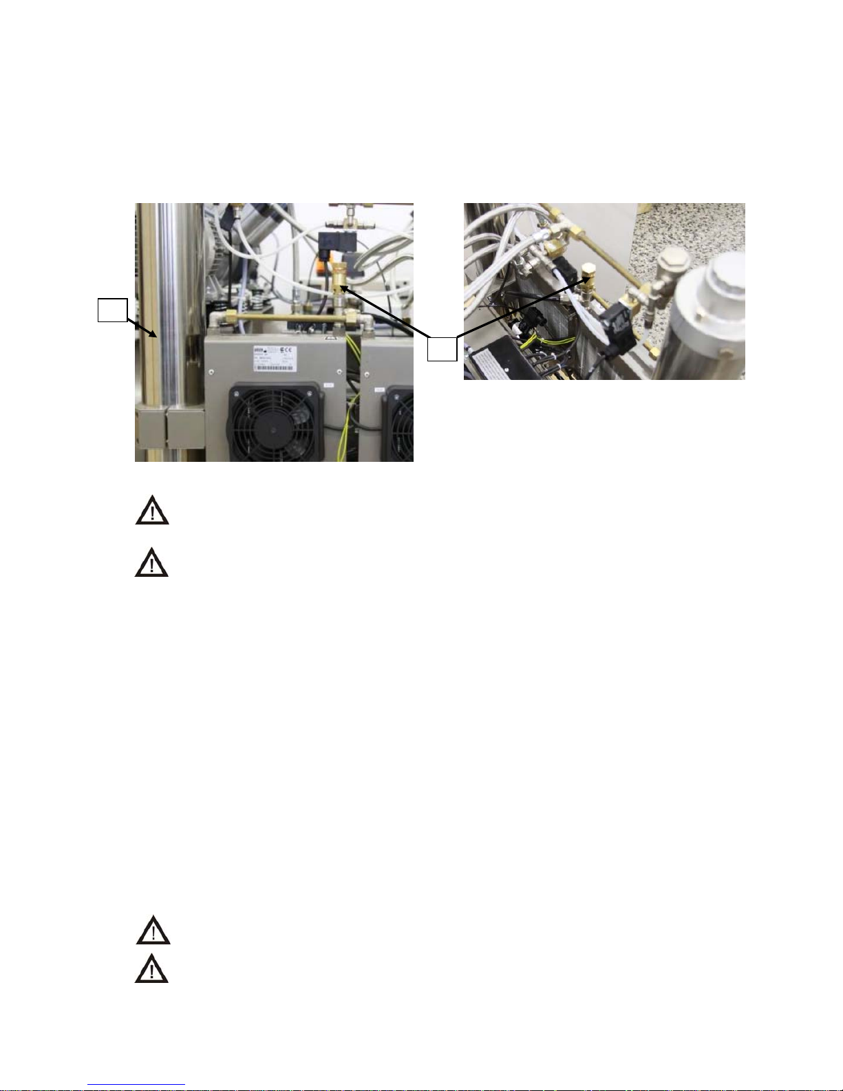
1. Safety valve
2. Dryer
Fig.1
Connect to output of ball valve with internal G3/4“ thread distribution of compressed air.
Connect electric supply of required parameters to input terminals of circuit breaker FA1 and
bridge of PE and N.
The safety valve is mounted into the pressure circuit of the compressors in front input solenoide valve.
In case of an additional assembly (Fig. 1) it is necessary to replace the „T“-piece G3/8“ by „X“-piece
(cross) G3/8“-1/4“ and sealing Cu 4KA-078.
For an additional assembly of the safety valve, it is necessary to adhere to the safety
measures referred to in the paragraph Product maintenance .
At the connection of device to distribution system TN-S, do not interconnect reset
bridges of PE and N !
7. PUTTING THE PRODUCT INTO OPERATION
After assembly and connection of the device to electric mains of 3 x 400V+N+PE, put both circuit
breakers FA5 and FA6 to I position. Then switch on switch of pressure switch SP, when all four
compressors shall be put into operation, two immediately (M1, M2) and two (M3,M4) after time delay
of 1-2 s. (adjusted at KT1). AS main switch, you may still use switch of pressure switch SP. After the
first connection of compressor to mains voltage, the pressure in common air chamber shall be
increased up to the value of switching off pressure SP (8 bar), when compressors shall be
automatically switched off. In further cycles, the compressors work in automatic mode, i.e. according
to the consumption of compressed air the compressors are switched on (at 0.6 MPa) and switched off
by pressure switch SP.
After prolonged operation of compressors or when temperature is increased at surface of engines
above 40oC, thermal switches ST1 ( ST2 ) shall switch on cooling ventilators EV1 and EV2 ( EV3 and
EV4 ) thus cooling of compressor aggregates shall be ensured even during their break. After
decreasing temperature in the space around engine under cca 35oC the relevant ventilators shall
again switch off. ventilators EV1 and EV2 ( EV3 and EV4 ) are always switched on at the same time
with engines of compressors M1 and M2 ( M3 and M4 ).
Such installed compressors do not require any attendance during operation. In next mode, the
compressors work automatically.
Pressure switch located on the air chamber has beforehand adjusted pressure value.
It is not allowed to change this value by readjusting of pressure switch.
The pressure presetting of safety valve is forbidden!
1
2
Page 8
OPERATION MANUAL DK 50 4x2V/M
NP-DK50 4x2V-M-EN-16_11-2015 11/2015
8
8. PRODUCT MAINTENANCE
The device is construed and produces so that its maintenance was minimal. For due and reliable
activity of compressor it is however necessary to make works according to the following description.
Prior to starting the works related to the maintenance of compressor, it is necessary
to check, whether it is possible to disconnect compressor from appliance,so that
there occurred no possibility ofdamage or endangerment life of a person using the
given appliance!
Further, the given works may be executed only by trained employee as follows:
In the case of previous operation of compressor, the head, cylinder, pressure hose
between hose and air chamber may be of hot temperature - do not touch the given
parts!
8.1. Replacement of the input filter and prefilter
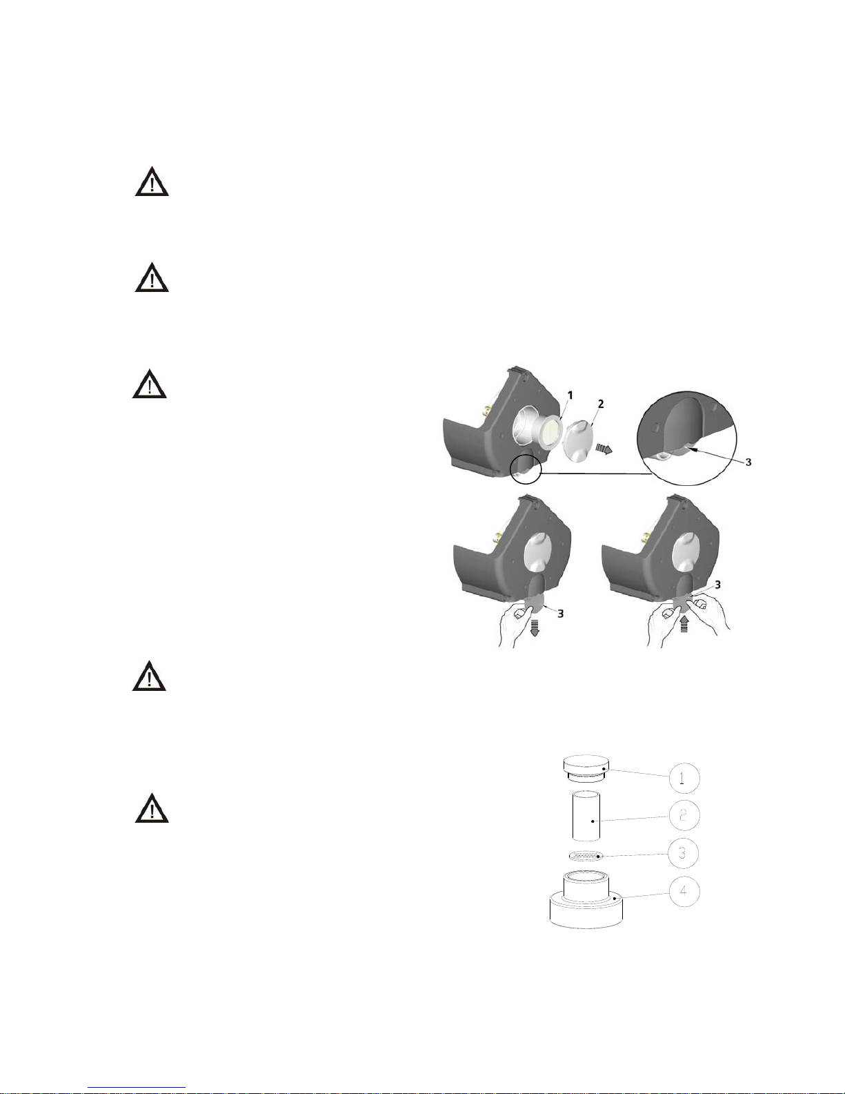
(Fig. 2)
At regular equipment operation
it is necessary to exchange
filter placed in the lid of crank
box of a compressor in the
prescribed time (Tab.1) .
At the lid of the compressors crankcase is
an input filter (1) and prefilter (3).
Replacing of the input filter:
Hand pull the rubber stopper (2).
Remove used and dirty filter.
Input new filter and set rubber stopper.
Replacing of the prefilter:
Hand pull prefilter (3).
Replace old prefilter with new.
Before beginning of works performance switch off the main circuit breaker into
position “0“ and wait for the dryer regeneration to complete – air stops to come out of
output solenoid valves.
8.2. Replacement / cleaning of filter in air dryer
(Fig.3)
At regular equipment operation it is necessary to
exchange the filter element and pre-filter placed in the
upper dryer head in the prescribed time (Tab. 1).
Remove dryer plug (1) by unscrewing anti-
clockwise.
Remove the filter (2).
Clean the screen (3) if neccessary. It is possible to
check or to change the filling (when dirty or to dusty
or the dryer doesn´t dry).
Put a new filter (2).
Refit dryer plug to the dryer head (4) and tighten it by
hand (clockwise).
Fig. 3
Obr.2
Page 9
OPERATION MANUAL DK 50 4x2V/M
NP-DK50 4x2V-M-EN-16_11-2015 11/2015
9
8.3. Check of safety valve
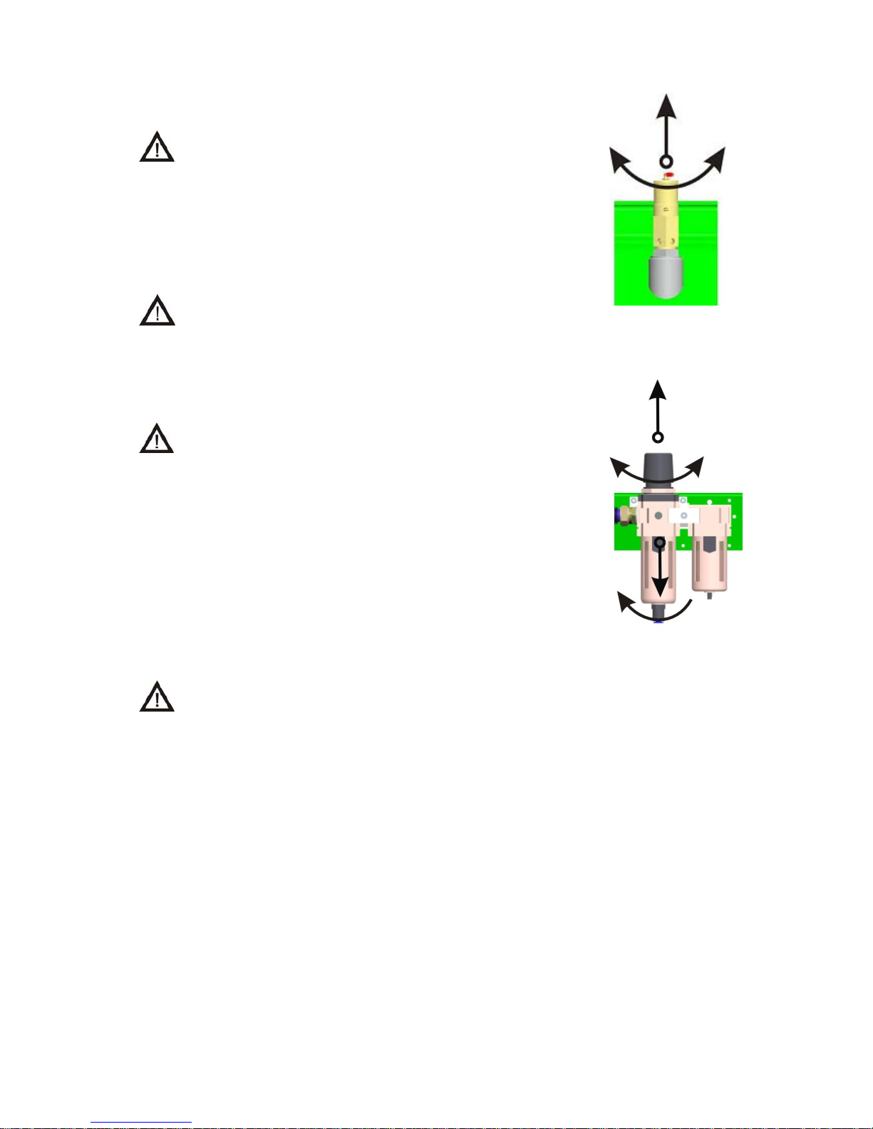
(Fig. 4)
The safety valve is set to the maximum permitted pressure
by the manufacturer. It must not be readjusted!
Turn the screw of the safety valve several rotations to left until
safety valve puffs.
Let safety valve freely puff only for a short period of time.
Turn screw to the right until the limit is reached, the valve must
be now be closed.
The safety valve must not be used for depressurising the
pressure tank. It could endanger the function of the safety
valve.
8.4. Replacement of filter element in filter
(if not part of the product) (Fig. 5)
Prior the intervention to the appliance it is necessary to
decrease the pressure of air in air chamber to zero and to
disconnect the appliance from mains.
Loosen lock on filter by pulling it down.
Slightly turn the cover of filter to left and pull it out.
Slightly turn the holder of filter to left and pull it out.
Replace filter, place the new filter back to the body and secure it
by holder of filter by slight turning to right. Vessel wash to soap
water.
Place the cover of filter and secure it by turning to right till
locking.
8.5. Regulation output pressure air regulator
(if it is part of the product) (Fig. 5)
Setting is necessary to be performed at pressured air
tanks and switched-off aggregates (i.e. in operation
break, immediately after aggregate switch off).
.
Lift the control button of the regulator and rotate. Set the pressure of the output pressure by
0,2 bar more than the demand (following the construction of regulator) for a running
compressor and to check it on a manometer.
After setting the pressure, lock the control button of the regulator turning and pushing.
Fig. 4
Fig. 5
Page 10
OPERATION MANUAL DK 50 4x2V/M
NP-DK50 4x2V-M-EN-16_11-2015 11/2015
10
8.6. Replacement of the buoy in the water separator
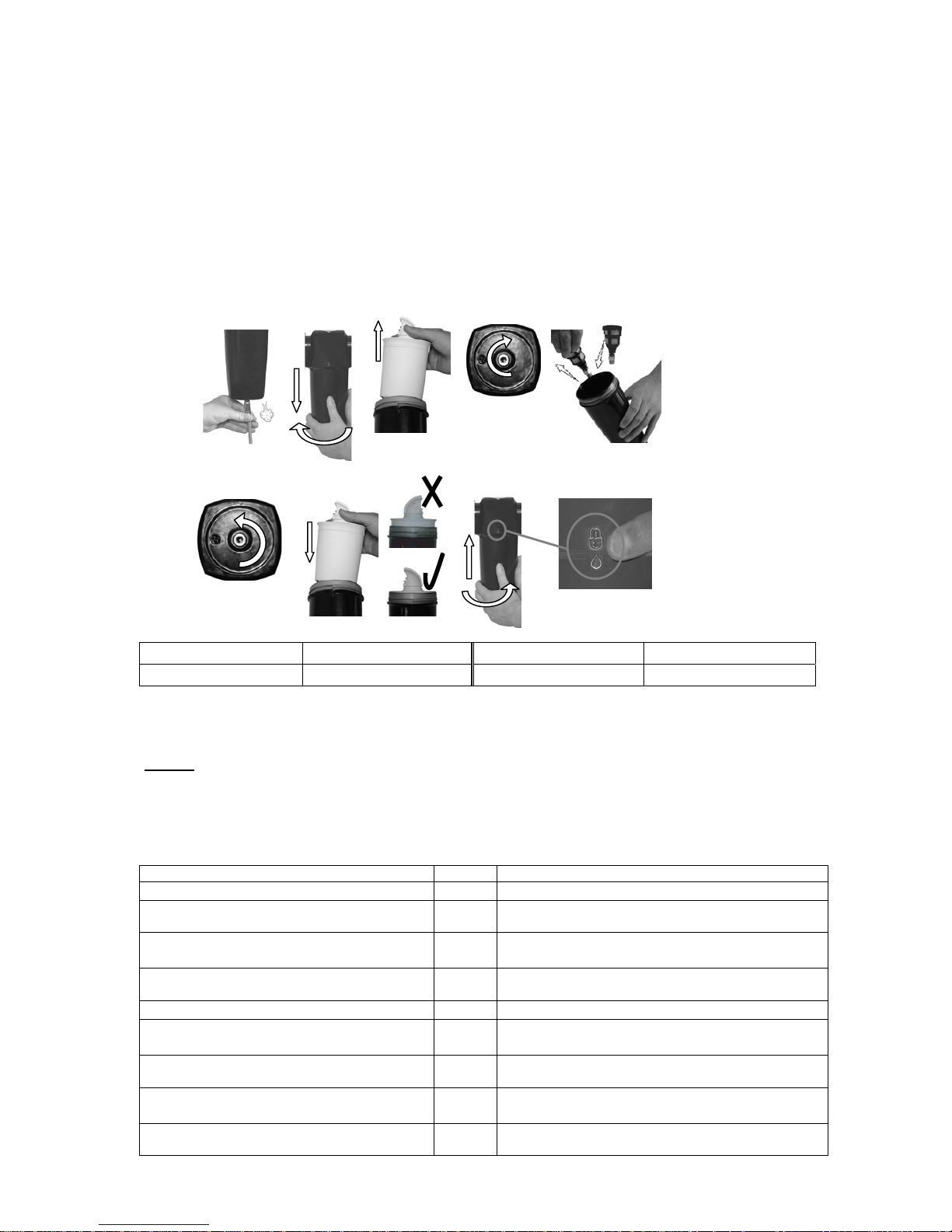
(Fig.6)
During regular operation of drier is necessary to change the buoy in the water separator.
A) Release pressure.
B) Dismount separator container.
C) Pull out condenser separator
D) Release nut of the buoy placed in the bottom part of the container.
E) Pull out worn buoy of the separator and replace it for the new one.
F) Secure the buoy with the nut in bottom part of the container.
G) Place the condenser separator back as shown in the picture.
H) Container of the separator insert back and screw in.
I) The container is definitely secured in the point of the symbol.
Fig. 6
Water separator Order number Buoy Order number
WS010BBFX 025200119 EF1 025200146
8.7. Intervals of maintenance
Notice!
The operating entity is obliged to ensure that all tests of the equipment are carried out
repeatedly at least once within every 24 months (EN 62353) or in intervals as specified by the
applicable national legal regulations. A report must be prepared on the results of the tests
(e.g.: according to EN 62353, Annex G), including the measurement methods used.
Tab.1
Maintenance range Figure Time interval (hour)
Check of safety valve Fig.4
1 x per annum
Check the bond tightness and checking
inspection of equipment
-
2000 hours, or after two years
Check the reverse valves activity, solenoid
valves
-
After dryer general overhaul or compressor
aggregate, after minimum of 4000h
Replacement of the input filter and
prefilter
Fig.2
1 x 2 years or after 5000 hours
Change of filtration element Fig.3
1 x per annum
Change of filter element in filter Fig.5
1 x per 1 year or when the pressure loss exceeds
0,1MPa
Replacement of the buoy in the water
separator
Fig.6
1 x year
Change of adsorbent in dryer -
After 4000h or after 4 years, or during general dryer
overhaul
Perform “Repeated Test” according
to EN 62353
- 1 x 2 years
A
B
C
D
E
F
G
H
I
Page 11
OPERATION MANUAL DK 50 4x2V/M
NP-DK50 4x2V-M-EN-16_11-2015 11/2015
11
9. INFORMATION ON REPAIR SERVICE
The guarantee and extended guarantee repairs are to be completed by the manufacturer, or an
organization authorized by the manufacturer.
Trained service personnel can only perform the activities connected to the troubleshooting guide!
The manufacturer reserves the right to modify the appliance in a way that will not
impact substantially on the operation of the appliance.
10. TROUBLESHOOTING AND SOLVING COMMON PROBLEMS
Prior to repairing the appliance it is necessary to reduce the pressure of the air in the
air chamber to zero and disconnect the appliance from the mains supply!
Trained service personnel can only perform the activities connected to the troubleshooting guide!
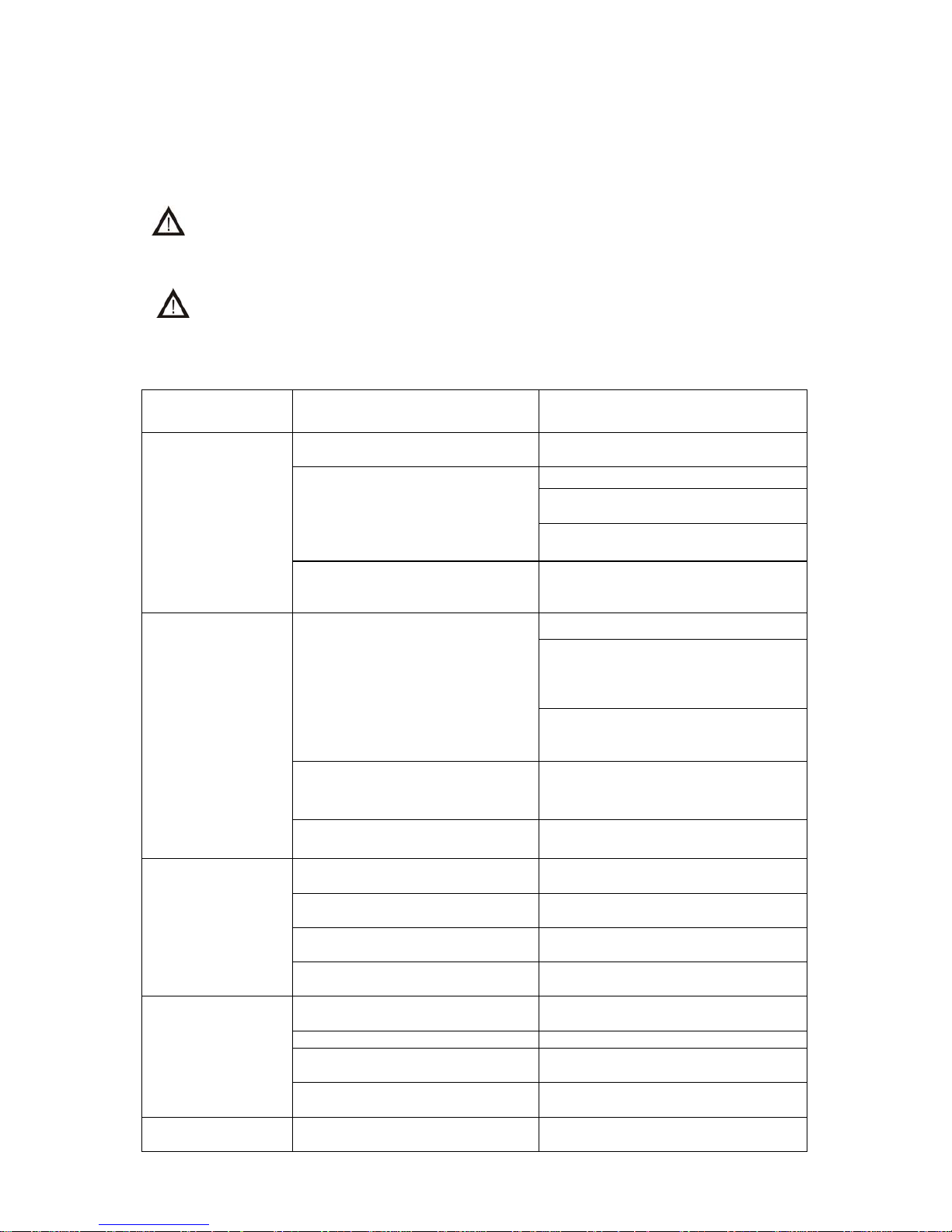
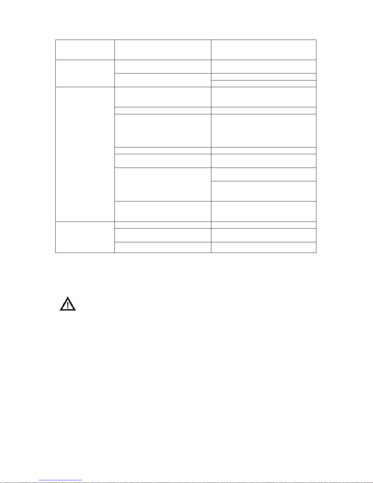
Tab. 2
TROUBLE POSSIBLE CAUSE WAY OF TROUBLE REMOVAL
No compressor
aggregate starts
running
Network voltage is missing
The main circuit breaker in the
distribution is turned off
Disconnected electric energy supply
Check the voltage in network
Released terminal in distribution box -
fasten
Check the main electric supply – change
the damaged one
The pressure switch does not switch
Check the terminal and functioning of
pressure switch – change the damaged
one
Some of the
aggregates do not
start running (the
signal light is on)
Discontinued electric energy supply
to the engine
Check the network voltage
Check the functions ,contactor, time
relay ( 3 and more aggregates), thermal
relay (3 aggregates on top of another) –
change the damaged ones
Released terminal on terminal board of
the engine- fasten the terminal, change
damaged or broken ones
Discontinues engine winding,
damaged thermal protection
Change the motor
Seized piston or other moveable part
(mechanic damage of movable parts)
Change the damaged parts
Compressor
aggregates are
switched often also
without air
consumption
Air leakage from pneumatic
distribution
Check the pneumatic distribution –
tighten the released bond
Untightness of reverse valves
Check and clean the reverse valves-
change the damaged one
After finished regeneration leakage
through solenoid valves
Clean or change the damaged one
Untightness of pressure switch and
safety valve
Check functioning and clean them–
change the damaged ones
Performance of some
compressor
aggregates is
lowered, cycle of
operation is
prolonged
Untightness on compressor
aggregate
Check the aggregate bond tightness –
tighten released bond
Worn piston ring Change the worn piston rings
Damaged sealing material between
head of cylinder and valve board
Change the seal ,- tighten
Contaminated input filter and
prefilter
Replace contaminated filters with the
new ones
Some of compressor
aggregates is noisy
Damaged piston pin bearing, small
end, motor bearing
Exchange the damaged matrix
Page 12
OPERATION MANUAL DK 50 4x2V/M
NP-DK50 4x2V-M-EN-16_11-2015 11/2015
12
(rattling, metal
noises)
Released (cracked) rubber
suspension spring
Exchange the damaged spring by
a new one
High outdoor air
quality compressor
(overheating)
Insufficient aeration of the room with
compressor
Provide suitable surrounding conditions
The cooling valves of compressor
aggregates or cooler do not work
False blowers - exchange
False thermal switch- exchange
The drying element
does not dry Low service pressure
Lower the air consumption, check the
source capacity, bond tightness of
joints, appliance condition
Non-functional solenoid valve Repair of change the valve
Blocked / wrong jet of regeneration
air
Clean the jet or use the right size of jet
(e.g. after decreasing number of
aggregates in the rack or after
compressor extent by rack with further
aggregates)
Non-functional cooler blower Exchange the blower
False time switch-over relay
Check the time relay setting or change
the relay
White liquid is released from
chambers
Exchange the drying substance and
bottom slab filter
Re-seal of check tightness (under
operation to pressure)
Dirty filters in dryer
Change inlet and outlet filter in
chamber, eventually drying substance
while it is decay or is dusty
Drying unit is noisy or
produces annoying
noise
False solenoid valve Change the valve
Damaged damping substance in the
condensate tank
Change the damping substance of the
tank
Damaged pressure hose Change pressure hose
After troubleshooting and re-assembly of the dryer, it is necessary to release received condensate
from air tanks, dry the air tanks and perform dryer regeneration, the best option is a continuous
compressor operation at pressure of around 0,7 MPa for at least 1 hour and perform air drying control.
Physical features of dryer adsorbent are changing during usage and its exchange is
necessary according to service interval Tab. 1. At the same time we suggest
adsorbent exchange during the dryer general overhaul.
Page 13
OPERATION MANUAL DK 50 4x2V/M
NP-DK50 4x2V-M-EN-16_11-2015 11/2015
13
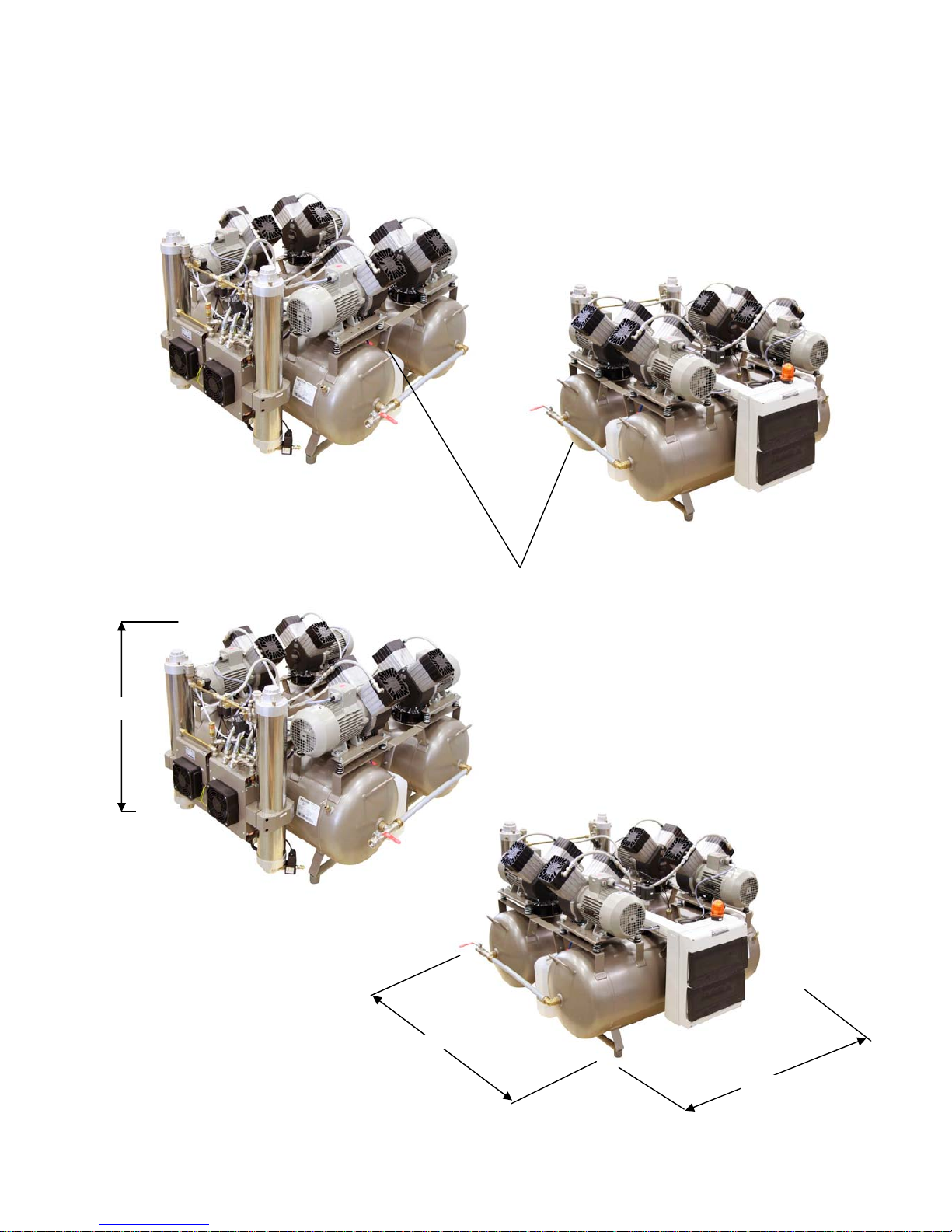
11. ENCLOSURES
Connecting pipe
970 mm
Page 14
OPERATION MANUAL DK 50 4x2V/M
NP-DK50 4x2V-M-EN-16_11-2015 11/2015
14
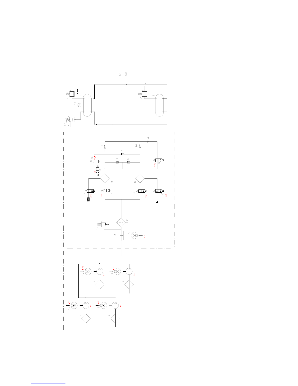
12. PNEUMATIC SCHEMA
LEGEND
1. COMPRESSORS M1-M4
2. FILTER ELEMENT
3. COOLER
4. INPUT SOLENOID VALVE
5. ADSORPTION AIR DRYER
6. JET
7. SOLENOID OUTLET VALVE
8. AIR TANK
9. PRESSURE SWITCH
10. SAFETY VALVE
11. MANOMETER
12. FAN OF COMPRESSOR
EV1 – EV4
13. FAN OF DRYER - EV
14. -
15. -
16. RETURN VALVE
17. OUTLET VALVE
18. SOLENOID. VALVE OF
REGENERATION
19. RELIEF VALVE
20. WATER SEPARATOR
Compressors agregates
Adsorption dryer
Page 15

OPERATION MANUAL DK 50 4x2V/M
NP-DK50 4x2V-M-EN-16_11-2015 11/2015
15
13. LIST OF COMPONENTS
Designation Name Type pcs
BOX
FA5
FA6
KM1-KM4
FA1-FA4
SB
HA
PH
KT1
KT2
KT3, KT4
KA
X1
X2, X3
X4
M1, M2
M3, M4
EV1-EV4
EV5-EV6
SP
ST1, ST2
YV2;YV3
YV1;YV4
YV5
YV6,YV7
Electric box
Breaker
Breaker
Contactor tape
Thermo relay
Push base
Optic lamp
Counter - M1-M4
Time relay - motors
Time relay - dryer
Time relay - regeneration
Relay
Terminal board U, V, W
Terminal board
Terminal board
Electromotors 1
Electromotors 2
Fans
Fans - dryer
Pressure switch
Thermo switch
Solenoid valve of dryer – IN
Solenoid valve of dryer – OUT
Solenoid valve of dryer - regeneration
DOMINO
C / 25A / 3
B / 4A / 1
C9, 230V
6,3A
MTX-10-TB / 230V
typ 210 300 00
230V, 50Hz
MCR
MCR
MCR
4p,230V/6A
RSDPS10
RSDPS10
typ 6336.30 11pol.
1,5kW, 400V, 50 Hz
1,5kW, 400V, 50 Hz
4715MS
4715MS
MDR 2/11, 230V
RH 2452
EV250B-12BD G 12E NO
21M0AV25
EV210A, NC
1
1
1
4
4
1
1
1
1
1
2
1
3
4
1
2
2
4
2
1
2
2
2
3
Page 16

OPERATION MANUAL DK 50 4x2V/M
NP-DK50 4x2V-M-EN-16_11-2015 11/2015
16
14. RANGE OF DELIVERY
DK50 4x2V/M ...........................................................
1x
DK50 4x2V ...........................................................
1x
Installation, operation, maintenance manual NP-DK50 nx2V/M
1x
Filter element of dryer AF40P-060S 025200079
2x
Packing of basic equipment checked by
.......................................................................
Date of production
.......................................................................
.......................................................................
Signature
Page 17
NP-DK50 4x2V-M-EN-16_11-2015 01/2011
17
Tlakový spínač
SP 6-8 bar
Časové relé MCR-08
KT1 - 1 sek.
KT2 - 50 sek.
KT3 - 120 sek.
KT4 - 240 sek.
POZNÁMKA:
1. V kompresore DK50 4 x 2V bez sušièa MONZUN
ELEKTRICKÁ SCHÉMA DK50 4 x 2V
nie sú použité KT2, KT3, KT4 a prvky v èasti SUŠIÈ
5
6
5
6
W2
43
W2
U1
V2 W2
U2
PE
40°C
ST1
N
150°C
44
W1
43
V1
U1
M1
V2
U2
EV1
44
W1
150°C
V1
97
9812
95
96
5
3
4
6
A2426
N
1
A1
KM1
5
3
FA1
979895
96
31
2
4
04
03
42A2
N
A1
KM2
3
1
M2
V2
U2
EV2
44
150°C
W1
V1
M3
W2
V2
U2
43
U1
44
W1
43
150°C
V1
U1
97
98
5
FA2
6
95
96
31
42
6
04
5
03
4
A2
2
N
A1
KM3
31
97
98
5
FA3
6
95
96
13
2
4
04
6
03
5
A2
2
4
N
A1
KM4
13
40°C
M4
EV3
EV4
FA4
04
03
PEN4
5
ST2
YV5
YV6
YV1
YV2
YV3
X4
1
N
PE PE
N 2
3
X4
SP
N
A1
18
264
2
U
1
W
V
5
3
PE
Cu 5G x 2,5
L2
L1
L3
FA6
PE
X1
FA5
1
N
p >
16
T
15
1518
16 16
18 15 18
KT2
A2
T
KT1
KT3
3/N/PE ~ 400/230 V 50...60 Hz
ELEKTRICKÝ PREDMET TR. 1
ELECTRICKÁ SIE TN-S [TN-C-S]
TYP B
34
31
X2
15
16
12
PE
N
0000
A2 41
KT4
PH
424432
1
1121 A1
6
X3
2
1
BOX
1222 24KA14
5
SB
HA
2
EV5
EV6
SUŠIÈ
A2TA1
T
T
T
A1 A2
T
A1 A2
T
KT2KT1
a
AST
ZP
TL
t x aat x a
MONtAST
IZ
UnZPTL
MON
t
IZ
Un
KT4
MON
KT3
t x a
a
MON
IZ
Un
t
AST
ZP
TLIZUn
t x a
a
t
AST
ZP
TL
YV7
YV4
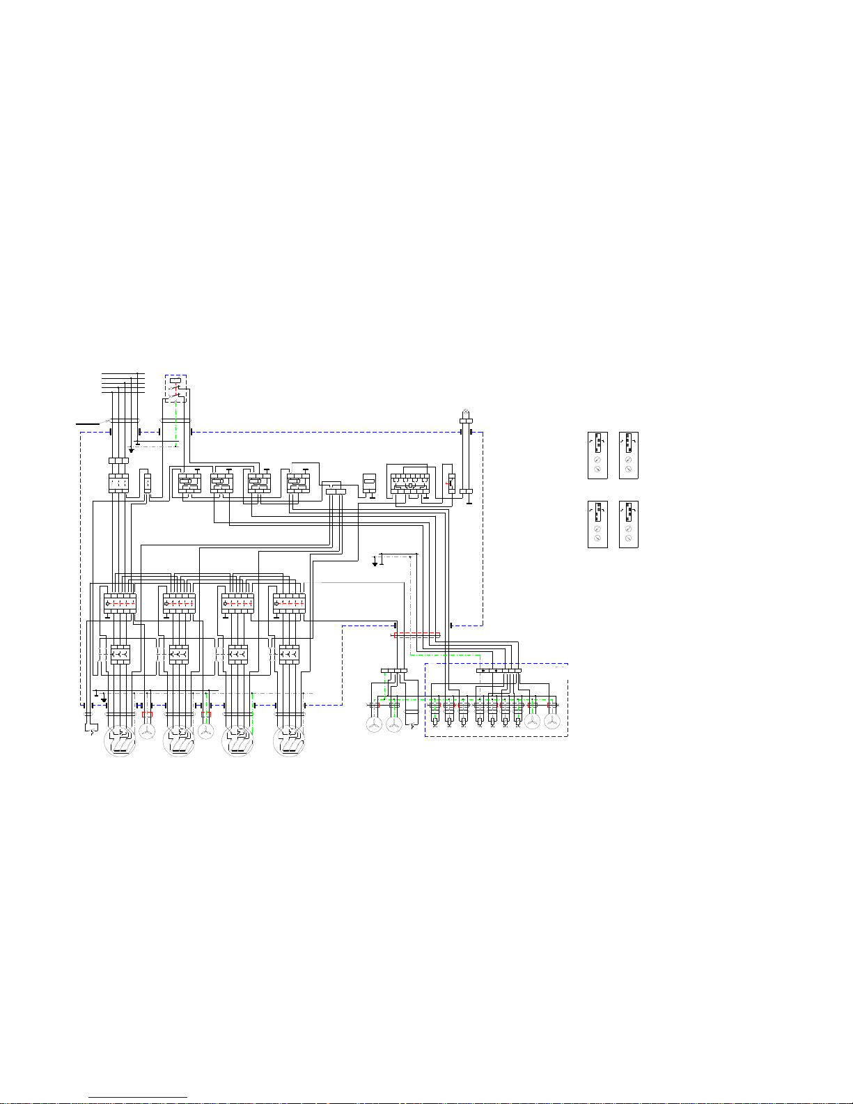
Pressure switch
SP 6-8 bar
Time relay MCR-08
KT1 - 1 sec.
KT2 - 50 sec.
KT3 - 120 sec.
KT4 - 240 sec.
ELEKTRICAL DRAFT DK50 4x2V
3/N/PE ~ 400/230V 50..60Hz
Mains TN-S (TN-C-S)
Elektric object of the 1.cat
B type
Notice:
In compressor DK50 4x2V without dryer aren´t used components in
part DRYER.
DRYER
BOX
 Loading...