

Ekol Clarity 30 Boiler Installation And Operating Instructions Manual
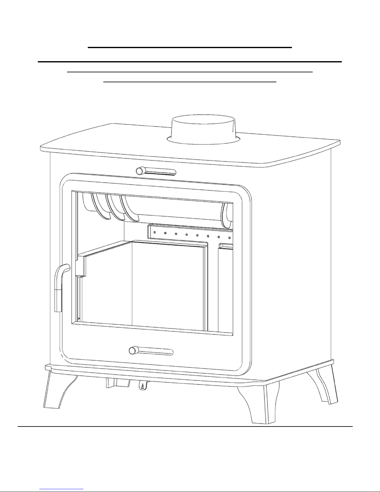
Ekol Clarity 30 Boiler Woodburning Stove
INSTALLATION AND OPERATING INSTRUCTIONS.
REF: Ekol Claity 30 Boiler Wood Version, MANUAL Version 1.1
MANUAL PUBLICATION DATE: 22.01.2014
Recommended as suitable for exemption under section 21 of The Clean
Air Act 1993 for use within UK Smoke Control Area.

Ekol Clarity 30 Boiler Woodburning Stove, – INSTALLATION AND OPERATING INSTRUCTIONS.
REF: Ekol Clarity 30 Boiler Wood Version, MANUAL VERSION 1.1
DATE: 22.01.2014
INTRODUCTION
SAFETY
Safety is the most important consideration when using and installing your stove. If not installed and used correctly, a house
fire could result. Installation must comply with relevant national and local Building Regulations and fire safety standards.
IN THE EVENT OF CHIMNEY FIRE, EVACUATE THE PROPERTY AND CALL THE EMERGENCY SERVICES.
Your stove will be heavy and care needs to be taken when lifting - 4 people will normally be required to lift.
UNPACKING
Your stove will have several of its components stored inside the stove itself for transportation.
Do NOT drag the stove on its legs – it must be carefully lifted into place.
Inside the stove will be a flue connector collar. This simply bolts with the fixings provided onto the top or rear outlet of the
stove, depending on your choice of installation type. Ensure to secure the supplied circular blanking plate onto the other
outlet using a good bead of fire cement to seal both the collar and the blacking plate.
Inside the stove will also be an ash-pan which sits underneath the grate, and will require regular emptying. You will also find
a detachable tool for removal of the ash-pan.
You will also find a glove which must be used when opening the door or when adjusting air vents when the fire is hot.
There is also a removable baffle plate which rests on the top of the cylindrical section of the water jacket and the rear of the
firebox (see diagram fig1.) this plate can be removed periodically to aid cleaning of the stove flueways and for easier access
to the flue system. It is vital that the baffle is always replaced before use.
INSTALLATION
Installation of your stove must comply with relevant local and national Building Regulations and fire safety standards.
TECHNICAL
Your stove has been tested to CE and British standards conforming to EN 13240.
Model; “Ekol Clarity 30 boiler”
Nominal heat output total – 19.2 kW
Nominal output to space – 9 kW
Nominal output to water – 10.2 kW
Net Weight of Stove - 220 kg.
Max Height - 725 mm (see also Diagram Fig.2)
Max Width - 767 mm
Max Depth - 536 mm
Flue Diameter - 150mm (6”)
Mean flue gas temperature directly downstream of the flue spigot - 322 degrees C. (with closed doors).
Flue gas mass flow – 15.8g/s
Mean CO emission (at 13% Oxygen) – 0.48%
Net Energy Efficiency 73.8%
Maximum operating water pressure 2 BAR

The stove must not be installed within the specified minimum distances to combustible materials: A gap of at least 200mm
needs to left between the stove and any combustible materials at the sides and 200mm to the rear. Adjacent walls should be of
non-combustible materials and construction, preferably masonry or brickwork.
All combustible items must be kept well clear of the stove, including log store, furniture, curtains etc and any item movable
or otherwise which may pose a fire hazard.
Your stove will require a constant air supply, and should not be used at the same time and in the same room/space as
extractor fans or any device which may draw air supply away from the stove.
The stove should be installed on a level floor with adequate load bearing capacity.
The stove needs to stand on a hearth of non-combustible materials not less than 12mm thick conforming to Building
Regulations.
At least one permanent external air vent should be installed in the same room as the stove, to ensure a constant air supply for
combustion. It should consist of a total free area of at least 10500mm². – ie a square opening of 100mm x 100mm would be
the minimum requirement. The vent should be positioned such that it is not liable to blockage.
NOT suitable for installation in a shared flue system.
If installed in a standard type chimney, a register plate needs to be fitted inside the chimney.
When purchasing flue pipe, 6” diameter is required. The flue pipe must be fitted INSIDE the flue spigot, and sealed with a
generous amount of Fire Cement.
Access should be provided for cleaning the flue gas connector and chimney flue to ensure that the passageways for exhaust
gases remain free from obstruction.
Flue Draught
Flue draught should be measured at full output when up to full operating temperature and must be within the following limits:
12 to 18 Pascals. – If the flue draught at full output exceeds the upper limit, then a suitable flue draught stabiliser must be
fitted to avoid overfiring and to allow sufficient burn-rate control.
We recommend that you have a qualified fitter install your stove. The British recognised standard for solid fuel installations
is HETAS. You can find a HETAS qualified installer in your area by going to the HETAS website – www.hetas.co.uk.
Plumbing
IMPORTANT: - your stove MUST be plumbed in before use. Under no circumstances should it be ‘run dry’ – this
would likely cause significant damage which would not be covered under warranty.
Please note: Saltfire Stoves do not design heating systems. A suitably qualified installer should produce a safe system
design with detailed plans following a site survey. The design should be in conjunction with relevant local and national
Building Regulations.
The information provided below is intended to help as a minimum requirements guide only.
Open Vented Only
Your stove is suitable only for use in open vented systems – this means that it must be installed such that there can be no risk
of the boiler jacket pressurising with increased water temperature. It must never be installed into sealed/ pressurised systems.
However, using safe methods of system ‘link-ups’ your stove can be used when installed safely, in conjunction with other
heating sources which may themselves be sealed systems. An example of this would be to use a thermal store with suitable
automatic control system.
For a traditional basic ‘gravity’ system which enables indirect heating of a DHW (domestic hot water) cylinder and a pumped
radiator heating circuit, a diagram is included in this manual as an example only (Diagram Fig.3) – please note this diagram is
 Loading...