

EKO Instruments Modbus 485 Instruction Manual

Modbus 485 RTU Converter
M-Box
Version Number: 1
INSTRUCTION MANUAL

EKO INSTRUMENTS CO., LTD MODBUS 485 RTU CONVERTER Instruction Manual V1
Pg. 1
1. Index
1.! Index 1!
2.! Important User Information 2!
2- 1. Contact Information !
2- 2. Warranty and Liability !
2- 3. About Instruction Manual !
2- 4. Environment !
2- 5. CE Declaration !
3.! Safety Information 5!
3- 1. WARNING/CAUTION !
3- 2. HIGH VOLTAGE WARNING !
4.! Introduction 6!
4- 1. Main Functions !
4- 2. Package Contents !
5.! Getting Started 8!
5- 1. Parts Name !
5- 2. Setup !
6.! USB Controller / Software
Error!Bookmarknotdefined.!
6- 1. Configuration !
6- 2. Installation !
6- 3. Electrical connection !
6- 4. Operating !
7.! Connect to peripheral device 17!
7- 1. Electrical connection !
7- 2. Operating !
8.! Troubleshooting 20!
8- 1. Troubleshooting !
9.! Specification 21!
9- 1. Main Unit !
9- 2. USB Controller and configurator software!
9- 2. Dimensions !
9- 3. Communication Specifications !

EKO INSTRUMENTS CO., LTD MODBUS 485 RTU CONVERTER Instruction Manual V1
Pg. 2
2. Important User Information
Thank you for using EKO Products
Make sure to read this instruction manual thoroughly and to understand the contents before starting to operate the
instrument. Keep this manual at safe and handy place for whenever it is needed.
For any questions, please contact us at one of the EKO offices given below:
2-1. Contact Information
EKO INSTRUMENTS CO., LTD.
Asia, Oceania Region
www.eko.co.jp
info@eko.co.jp
EKO INSTRUMENTS Co., Ltd.
1-21-8 Hatagaya, Shibuya-ku
Tokyo, 151-0072 Japan
Tel: +81 (3) 3469-6713
Fax: +81 (3) 3469-6719
Europe, Middle East, Africa Region
www.eko-eu.com
info@eko-eu.com
EKO INSTRUMENTS Europe B.V.
Lulofsstraat 55, Unit 32,
2521 AL, Den Haag, The Netherlands
Tel: +31 (0)70 3050117
Fax: +31 (0)70 3840607
North & South America Region
www.eko-usa.com
info@eko-usa.com
EKO INSTRUMENTS USA Inc.
95 South Market Street, Suite 300
San Jose, CA 95113 USA
Tel: +1 408-977-7751
Fax: +1 408-977-7741
2-2. Warranty and Liability
For warranty terms and conditions, contact EKO or your distributor for further details.
EKO guarantees that the product delivered to customer has been verified, checked and tested to ensure that
the product meets the appropriate specifications. The product warranty is valid only if the product has been
installed and used according to the directives provided in this instruction manual.
In case of any manufacturing defect, the product will be repaired or replaced under warranty. However, the
warranty does not apply if:
! Any modification or repair was done by any person or organization other than EKO service
personnel.
! The damage or defect is caused by not respecting the instructions of use as given on the product
brochure or the instruction manual.

EKO INSTRUMENTS CO., LTD MODBUS 485 RTU CONVERTER Instruction Manual V1
Pg. 3
2-3. About Instruction Manual
Copy Rights Reserved by EKO INSTRUMENTS CO., LTD. Making copies of whole or parts of this
document without permission from EKO is prohibited.
This manual was issued: 2015/04/05
Version Number: 1
2-4. Environment
1. WEEE Directive 2002/96/EC
(Waste Electrical and Electronic Equipment)
This product is not subjected to WEEE Directive 2002/96/EC however it should not be mixed with general
household waste. For proper treatment, recovery and recycling, please take this product(s) to designated
collection points.
Disposing of this product correctly will help save valuable resources and prevent any potential negative
effects on human health and the environment, which could otherwise arise from inappropriate waste
handling.
2. RoHS Directive 2002/95/EC
EKO Instruments has completed a comprehensive evaluation of its product range to ensure compliance with
RoHS Directive 2002/95/EC regarding maximum concentration values for substances. As a result all
products are manufactured using raw materials that do not contain any of the restricted substances referred
to in the RoHS Directive 2002/95/EC at concentration levels in excess of those permitted under the RoHS
Directive 2002/95/EC, or up to levels allowed in excess of these concentrations by the Annex to the RoHS
Directive 2002/95/EC.

EKO INSTRUMENTS CO., LTD MODBUS 485 RTU CONVERTER Instruction Manual V1
Pg. 4
2-5. CE Declaration
DECLARATION OF CONFORMITY
We: EKO INSTRUMENTS CO., LTD
1-21-8 Hatagaya Shibuya-ku,
Tokyo 151-0072 JAPAN
Declare under our sole responsibility that the product:
Product Name: Modbus Signal Converter
To which this declaration relates is in conformity with the following harmonized
standards of other normative documents:
Harmonized standards:
EN 61326-1:2006 Class A (Emission)
EN 61326-1:2006 (Immunity
Test was done in this condition which are signal cable length is under 3m and used the
metal box.
Following the provisions of the directive:
EMC-directive: 89/336/EEC
Amendment to the above directive: 93/68/EEC
Date: Mar. 6, 2015
Position of Authorized Signatory: Deputy General Manager of Quality Assurance Dept.
Name of Authorized Signatory: Shuji Yoshida
Signature of Authorized Signatory:
EKO INSTRUMENTS CO., LTD MODBUS 485 RTU CONVERTER Instruction Manual V1
Pg. 5
3. Safety Information
EKO Products are designed and manufactured with consideration for safety; however, please make
sure to read and understand this instruction manual thoroughly to be able to operate the instrument
safely in the correct manner.
WARNING
CAUTION
Attention to user; pay attention to the instructions given on the
instruction manual with this sign.
HIGH
VOLTAGE
WARNING
High voltage is used; pay special attention to instructions given on
this instruction manual with this sign to prevent electric leakage
and/or electric shocks.
3-1. WARNING/CAUTION
1. Setup
! Do not install MODBUS 485 RTU CONVERTER in a place where the MODBUS 485 RTU
CONVERTER may get wet or soaked in water.
! Do not install MODBUS 485 RTU CONVERTER in direct sunlight.
! Use with fuse around 0.5A connected in series on the power supply cable. Depending on the
power supply connected, large current may flow when the internal malfunction occur, and may lead
to generating heat and fire.
3-2 . HIGH VOLTAGE WARNING
1. Power Supply
! Always check the voltage and AC/DC type for the specified supply power before connecting the
MODBUS 485 RTU CONVERTER. If wrong type of power supply is connected, it may cause
MODBUS 485 RTU CONVERTER malfunction and lead to accidents.

EKO INSTRUMENTS CO., LTD MODBUS 485 RTU CONVERTER Instruction Manual V1
Pg. 6
4. Introduction
The MODBUS 485 RTU converter called "M-Box" is a digital signal conditioner to convert the Voltage output of a
solar radiation sensor, PT-100 or 10kΩ NTC temperature sensor into a MODBUS 485 RTU output. The converter
can be used with all passive EKO radiometers or any other mV sensor to be connected to data loggers or inverters
with a MODBUS 485 RTU input channel. By using the signal conditioner the sensor cable can be easily extended
over long distances without any signal loss or potential electromagnetic interference in noisy industrial
environments. With MODBUS up to 100 different sensors and converter units can be addressed and connected in
parallel.
The mV signal of the solar sensor will be converted to irradiance 0 - 1600 W/m2. In this case the sensitivity factor of
the solar sensor will be set to the converter. With the optional USB controller and EKO Sense software (Multiple
languages) the converter settings can be freely changed. This tool will be needed in case the sensor sensitivity
might need to be changed after a periodical solar sensor re-calibration.
For practical installation, the converter is placed in an IP65 Aluminium box with universal cable glands. It has
robust input/output screw terminals, which can be easily connected to the signal cable that leads to the
measurements system at the installation site. EKO can pre-connect the solar sensor cable to simplify your
process.
4-1. Main Functions
• The converter proportionally converts the solar sensor output voltage (V) into irradiance (W/m2).
• Input (mV, PT-100 (2,3,4W), NTC 10kΩ) / Output irradiance (W/m2) and Temperature
• Up to 100 converters in one system.
• In combination with a solar sensor sensitivity will be pre-set.
• In case of a sensor re-calibration, the converter-setting scan be easily changed with the optional
USB controller and EKO sense software.

EKO INSTRUMENTS CO., LTD MODBUS 485 RTU CONVERTER Instruction Manual V1
Pg. 7
4-2. Package Contents
Check the package contents first; if any missing item or damage is noticed, please contact EKO immediately.
Table 4-1 Package Contents
Standard Items
Qty.
Remarks
Signal Converter
1 unit
Integrated in Aluminium box with cable glands
3 pin header
1 pcs.
Converter output
Instruction Manual
-
Download from EKO website
Optional Items
Qty.
Remarks
USB/485 cable
1 unit
With
9V battery
1 pc.
9V battery cable
1 pc.
Software
-
Download from EKO website
EKO INSTRUMENTS CO., LTD MODBUS 485 RTU CONVERTER Instruction Manual V1
Pg. 8
5. Getting Started
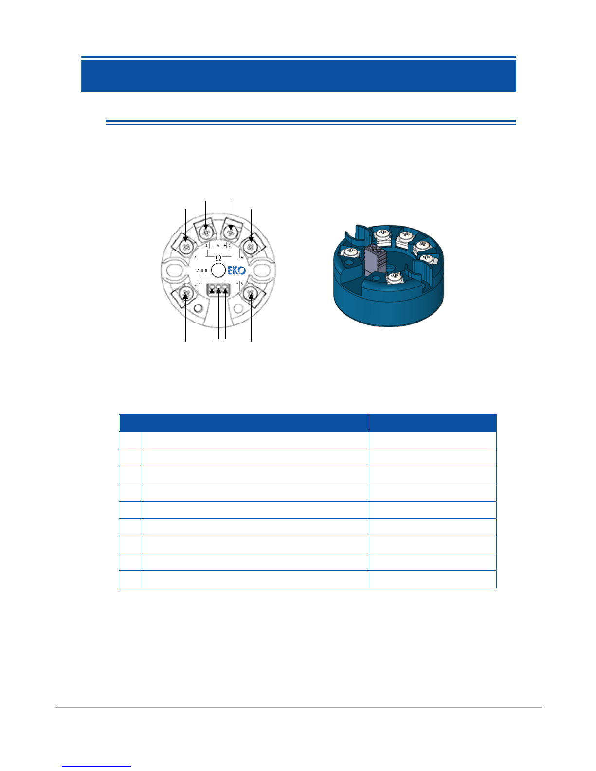
5-1. Parts Name
Each part name and its main functions are described below.
Table 5-1. Parts Name and Terminal Numbers
Parts Name
Terminal Numbers
1
Pyranometer Signal Input (mV, (-)) Terminal 1
1
2
Pyranometer Signal Input (mV, (+)) Terminal 2
2
3
PT-100 / NTC Signal Input Terminal 3
3
4
PT-100 / NTC Signal Input Terminal 4
4
5
Power Supply Input Terminal ( - )
5
6
Power Supply Input Terminal ( + )
6
7
Modbus Output Terminal (A)
A
8
Grounding Terminal
G
9
Modbus Output Terminal (B)
B
Figure 5-1. Parts Name
2 1 6 5
3
4
7 8 9
 Loading...