

Ekofires eko 5510, eko 5520, eko 5530 Installation And User Instructions Manual

installation and user instructions
All instructions must be handed to user for safekeeping
Revision B - 08/11
Country(s) of destination - GB/IE
eko 5510
eko 5520
eko 5530
high efficiency flueless gas fire
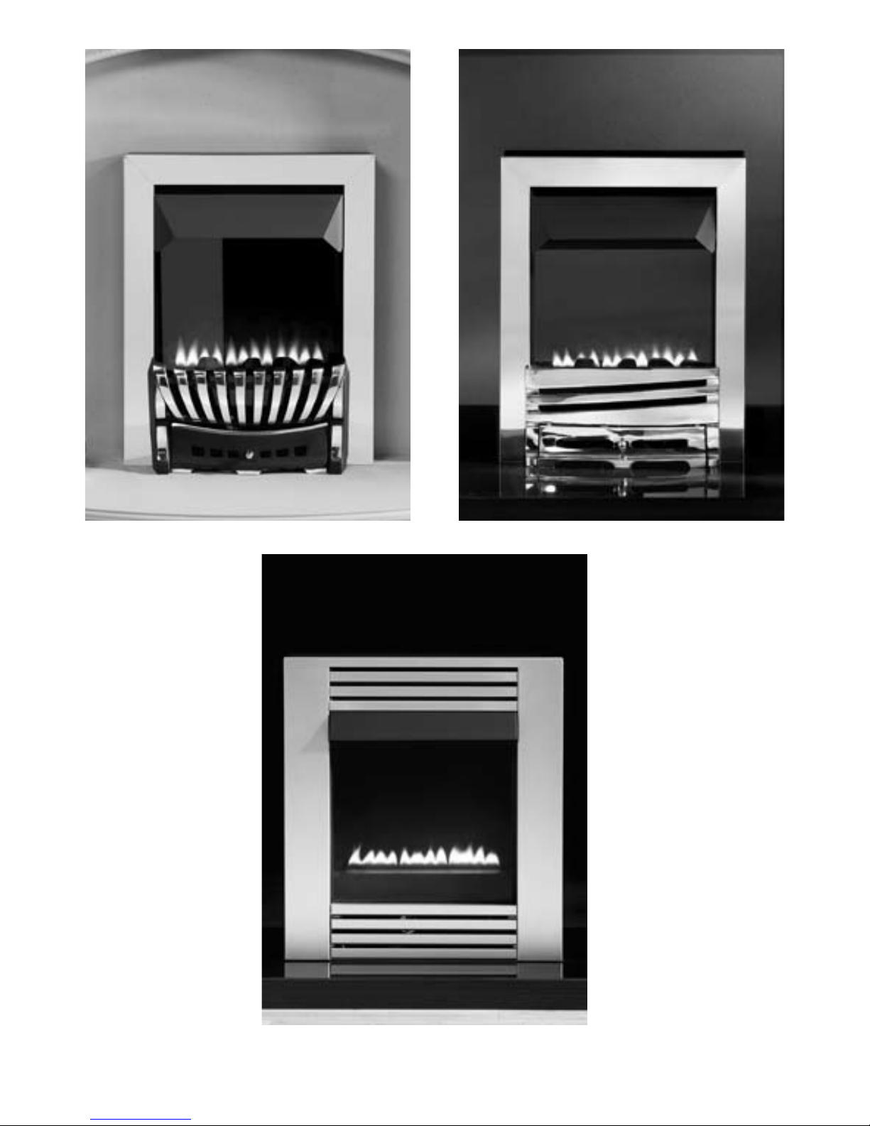
Eko 5510
© 2009 Focal Point Fires plc.
Eko 5520
Eko 5530

INSTALLATION INSTRUCTIONS
IMPORTANT NOTES
This appliance is a high efficiency, flueless catalytic flame effect gas fire. It provides radiant and convected warmth
both efficiently and safely utilising the latest type catalytic converter and burner technology. The appliance does
not require a flue system of any type as the catalytic converter cleans the flue products to provide a complete combustion system, which is intrinsically safe. It is designed to operate on Natural Gas (see data badge) and is factory set for operation on the gas type, and at the pressure stated on the appliance data plate.
The appliance incorporates a combustion monitoring system (Oxygen Depletion System). It must not be adjusted
or put out of operation. If replaced then manufacturer’s original parts must be used.
It is the LAW that all gas appliances and fittings are installed by a GAS SAFE registered person and in accordance
with the Gas Safety (Installation and Use) Regulations 1998, the relevant British Standards for Installation, Codes
of Practice and the Manufacturers' Instructions.
The installation shall also be carried out in accordance with the following:
Failure to comply with the above could lead to prosecution and deem the manufacturer’s warranty invalid.
This appliance must be installed in accordance with the rules in force and used only in a sufficiently ventilated
space. The appliance is designed to fit various types of situations as described in sections 3.0 and 4.0. The appliance must be installed in a correctly sized room (see section 3.1), and the correct purpose provided ventilation
must be provided (see section 4.1). It should be noted that heaters create warm air currents. These currents move
heat to wall surfaces next to the heater. Installing the heater next to vinyl or cloth wall coverings or operating the
heater where impurities in the air (such as tobacco smoke, candle smoke etc.) exist, may cause the walls to become
discoloured.
This appliance is intended as a secondary source of heat only and should not be used in a room without some
form of background heating present. If the appliance is used in a room as the sole source of heat, then condensation may occur on colder surfaces within the room.
On first light up of a new appliance, initial curing of high temperature paint and burning off of lubricants may
occur for the first few hours of operation. During this period some smoke may be emitted from the outlet grille,
this should be no cause for concern. Accordingly, the room should be well ventilated with all windows and doors
open during this period. During this period the appliance may cause smoke alarms to sound. If this happens, reset
the alarms, but do not remove the batteries.
Consult ALL instructions before installation and use of this appliance. This appliance is free from any asbestos material.
Please note: Except where otherwise stated, all rights, including copyright in the text, images and layout of
this booklet, is owned by Focal Point Fires plc. You are not permitted to copy or adapt any of the content
without the prior written permission of Focal Point Fires plc.
1
Section Contents Page No.
1.0 Important Notes 1
2.0 Appliance Data 2
3.0 Installation Requirements 2
3.1 Room Sizing 2
4.0 Site Requirements 2
4.1 Ventilation 5
5.0 Unpacking the Appliance 5
5.1 Component Checklist 5
6.0 Appliance Installation 5
6.1 Preparing the Appliance 5
6.2 Gas Supply Routes 6
6.3 Installation Method 1 6
6.4 Installation Method 2 7
6.5 Installation Method 3 8
6.6 Installation Method 4 9
7.0 Final Fitting 9
Section Contents Page No.
7.1 Cable Fixing 9
7.2 Checking the Burner & Spark Gap 10
7.3 Fitting the Fuel Bed (Euphoria models) 10
7.4 Fitting Decorative Hood/Frame 11
8.0 Testing and Commissioning 11
8.1 Operating the Appliance 11
8.2 Setting Pressure 12
8.3 Briefing the Customer 12
9.0 Servicing 12
9.1 Cleaning the Coals 13
9.2 Servicing the Burner Tray 13
9.3 Pilot Assembly 13
9.4 Catalyst 14
9.5 Testing for Firebox Leakage 14
10.0 Troubleshooting Guide 15
User Instructions
• Manufacturers' Instructions.
• The Building Regulations issued by the Department for Communities and Local Government, the Building
Standards (Scotland) (Consolidation) Regulations issued by the Scottish Development Department.
• Relevant British standards insofar as the relevant areas are not covered by these instructions.
• For Republic of Ireland, reference should be made to the current edition of IS813 (the relevant standards
governing installation).
1.0
© 2009 Focal Point Fires plc.

APPLIANCE DATA
INSTALLATION REQUIREMENTS
The fire has been designed to be installed in two main applications; either to fit into a suitable opening created in the inner leaf of an outside wall or false chimney breast/extended fire surround built to conceal the
appliance. The appliance can also be fitted into an unserviceable or inoperative fireplace served by a natural draught flue but the old flue must be sealed off. It will be necessary to ventilate the old flue to prevent
condensation and dampness forming, however any air vent used to ventilate the old flue must not be sited
within 500mm of this appliance. If the flue can be ventilated to the outside of the building then this is usually the best solution. If in doubt then advice should be sought from a local building control officer.
The appliance must be installed onto a suitable non-combustible insulating surface at least 12 mm thick
covering the entire base area of the box. The fire must be used with a back panel capable of withstanding
150°C minimum. Any combustible materials directly behind the fire frame (or back panel) and close to the
cavity box of the fire must be removed and replaced with non-combustible material such as cement, browning, 'Superlux' board or equivalent materials.
ROOM SIZING
The room size should be a minimum of 27m3(e.g. 11’ x 11’ x 8’) to allow adequate circulation of air and
ensure the correct operation of the fire. This volume may include adjacent spaces but these spaces must
not be separated by a door. To calculate a room size in cubic metres (m3) divide the room volume in cubic
feet (ft3) by 35.3.
SITE REQUIREMENTS
This appliance may be installed in any room in the home except bathrooms or bedrooms. Installation in living rooms is common, however other rooms such as kitchens, dining rooms and hallways are permitted,
providing a suitable natural gas supply is available, and rooms sizing and ventilation requirements are
strictly adhered to (see sections 3.1 and 4.1).
The appliance is designed to be versatile, and as such will operate correctly when exposed to normal gentle draughts experienced within the home. It is not recommended, however that the appliance be installed
in areas where it is likely to be exposed to persistent strong draughts, that may be generated by outside
doors or windows, air vents etc. It is recommended that the appliance should not be installed within 1 metre
of any air vent.
Gas Group
Inlet Pressure (± 2.0mbar)
Regulator Pressure
Max Energy Input (Gross)
Max Energy Input (Net)
Max Gas Rate
Min Energy Input (Gross)
Min Energy Input (Net)
Min Energy Input (Gross)
Min Energy Input (Net)
Burner Pressures High Cold (±1.5 mbar).
High Hot (±1.5 mbar).
Low Cold (± 0.75 mbar).
Low Hot (± 0.75 mbar).
Flow restrictor orifice
Injector
Oxypilot (SIT/Bray)
Gas control
Gas Inlet restrictor elbow
Ignition
Spark Gap (± 1.0mm)
All Models
G20 Natural Gas CAT I2H
20 mbar
N/A
2.3 kW
2.07 kW
0.23 m3/h
1.3 kW
1.17 kW
166 W
150 W
18.0 mbar
18.2 mbar
4.5 mbar
4.6 mbar
1.16 mm
N/A
9110
BM733/NGC8602D
8mm
Piezo spark
4.0 mm
2.0
3.0
3.1
4.0
2
©
2009 Focal Point Fires plc.
SITE REQUIREMENTS (continued)
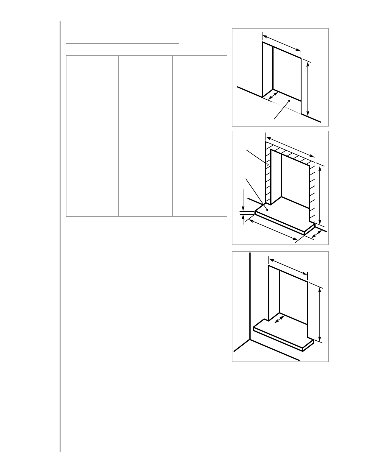
Basic opening sizes (all dimensions in mm)
The basic opening dimensions for the appliance are as follows;
The opening must be within these sizes in order to accommodate
the full depth of the fire box in non-combustible applications.
Applications involving combustible materials e.g. timber battens
in false chimney breasts, must use appropriate clearances and
insulation methods as described in the relevant section of these
instructions. Opening depth ‘c’ includes any plaster, cement or
infill/back panels that form part of the installation.
Consideration for cable fixings, any hearth that may be required
etc. should be made in addition to the basic sizes given in table 1.
• Cable fixings at rear - allow an extra 20mm depth.
• Hearth to be installed - allow the height of the hearth (minimum
50mm).
The appliance must be sited on a solid base (indicated in figure
1). This base may be combustible (i.e. laminate or wooden flooring) but must not be carpet or fabric of any kind. If the room in
which the appliance is to be installed is carpeted or has a fabric
floor covering then a small solid hearth will be required, meeting
the dimensions specified in table 1 and illustrated in figure 2.
In all installations, the wall or back panel of the installation must be flat, non-combustible and meet the
dimensions specified in table 1 and illustrated in figure 2.
The appliance may be installed as a ‘hole in the wall’ type installation, however a small hearth or ledge must
be provided to support the base of the appliance and decorative facia. In this situation the thickness of the
hearth or ledge may be as desired, but it must have the strength to support the weight of the appliance and
the facia.
4.0
‘
a’
‘b’
‘c’
‘e’
‘
d’
‘f’
‘i’
‘j’
‘
k’
Dimension:
‘a’ minimum
‘a’ maximum
‘b’ minimum
‘b’ maximum
‘c’ minimum
‘c’ maximum
‘d’ minimum
‘e’ minimum
‘f’ minimum
‘g’ minimum
‘g’ maximum
‘h’ minimum
‘h’ maximum
‘i’ minimum
‘i’ maximum
‘j’ minimum
‘j’ maximum
‘k’ minimum
‘k’ maximum
Eko 5510 & Eko 5520
560
610
410
470
105
None
50
560
140
560
As desired
655
As desired
560
610
410
470
105
None
Eko 5530
555
570
410
425
105
None
50
560
100
560
As desired
605
As desired
555
570
410
425
105
None
Figure 1
Figure 2
Base area
This area to be
flat and non-
combustible
Hearth
(if required)
‘h’
‘g’
Table 1
Figure 3
3
©
2009 Focal Point Fires plc.

SITE REQUIREMENTS (continued)
Clearances to non-combustibles
Non combustible surfaces are defined as brick, metal, marble, concrete etc. and also a number of manmade materials impervious to flame. If in doubt refer to the material manufacturer for further information
before proceeding with installation.
The wall/back panel for the opening must always be non-combustible. Bare plasterboard must be protected by non-combustible plaster or replaced with non-combustible material (e.g. Superlux board). Any gap
between wall boards and the wall must be filled using glass fibre insulation, silicone mastic or similar material to prevent heat ingress.
Any type of fire surround used with this appliance must be adequately sealed to the wall and floor to prevent excess draughts around the back of the fire. The temperature rating of any surround used must be
150°C minimum.
Clearances to the sides of the appliance are 100mm (4”). Clearance to the front of the appliance is 500mm
(20”).
The sides and back of the appliance may be installed directly onto a non-combustible surfaces.
A non combustible shelf of any depth may be positioned above the appliance provided it is no closer than
200 mm from the top of the appliance glass panel and the wall above the appliance is non combustible.
The shelf itself and any articles placed on it must also be tolerant of high temperatures.
Clearances to combustible materials
Combustible materials are defined as wood, fabrics, or other materials likely to combust if exposed to
flame. Generally, any material, which is likely to discolour, melt or misshape when exposed to moderate
heat, should be considered as a combustible material or surface.
Clearance to the sides of the appliance facia are 100mm (4”) but curtains, drapes and other fabrics are not
permitted within a distance of 500mm (20”) of the appliance sides. No such materials are permitted directly above the appliance regardless of distance.
The minimum clearance to the ceiling above the appliance is 800mm (31.5”) measured from the top of the
appliance glass panel.
Combustible materials should not be positioned directly in front of the appliance within a distance of one
metre.
A combustible shelf may be fixed to the wall above the fire, providing that it complies with the dimensions
given below.
The shelf depth may be greater but the height must also be increased accordingly. An increase in height of
25 mm is required for every 12.5 mm of additional shelf depth. For shelves that are too low protective
devices can be used such as metal heat deflectors, but it must be assured that the shelf does not reach an
unacceptable temperature before relying on such a solution.
Under no circumstances should any electrical equipment e.g. plasma screen TV sets etc. be positioned on
the wall above the appliance.
Clearance to the sides and rear of the firebox are a 75mm (3“) air-gap. Clearance to the top of the firebox
is a 100mm (4”) air-gap.
It should be established that any mirrors or picture frames etc. to be positioned on the wall above the appliance are able to withstand prolonged exposure to moderate heat and moisture before proceeding with their
installation.
If the appliance is to be mounted on a dry lined wall or a timber framed construction wall then the integrity and ability of the wall to carry the weight of the appliance must be confirmed. It is important in these circumstances that any vapour control barrier is not damaged, and that any structural members of the house
frame are not damaged - refer to section 6.5.
4.0
Maximum depth of shelf Minimum distance from hearth to underside of shelf
150mm 950 mm
100mm 850 mm
4
©
2009 Focal Point Fires plc.

VENTILATION
A minimum of 100 cm2purpose provided ventilation is required for this appliance. This may be achieved
either with one vent 100 cm2at a high or low position in the room, or split ventilation i.e. 50cm2be
installed at high level and 50cm2be installed at low level within the room. An openable window or equivalent is also required.
To reduce the possibility of draughts, road noise or insects entering the room via the air vent, we recommend the use of “Black Hole”, “Vortex” or “Centurion” type vents featuring internal baffles. The requirements
of any other gas, oil or solid fuel appliances operating in the same room or space must be taken into consideration when assessing ventilation.
Any ventilation fitted must comply with BS 5871 part 4 and BS 5440 part 2.
Ventilation fitted under, or within immediate vicinity of the appliance must not be used as it may adversely effect performance of the ODS system. For Republic of Ireland refer to the current edition of IS813 and
any relevant rules in force. The appliance shall not be installed within 1 metre of any existing air vent, and
any new air vent shall not be installed within 1 metre of the appliance.
UNPACKING THE APPLIANCE
Lift off the remaining packaging components. Check that the components supplied correlate with the component checklist. Please dispose of all the packaging materials at your local recycling centre.
COMPONENT CHECKLIST
APPLIANCE INSTALLATION
Note: Ensure that the gas supply is isolated before commencing installation of the appliance.
The fireplace opening and environment must be in compliance with specifications laid down in the appropriate sections of these instructions.
PREPARING THE APPLIANCE
Remove the appliance from its carton as described previously and stand on a dustsheet. Remove the hood
and glass panel and place safely to one side.
Knock out holes are provided in the rear and sides of the firebox for use where concealed pipework is
required. Note: Knock out holes are also provided in the sides of the inner firebox if a side-entry pipe routing is required, but it is essential to seal these holes with grommets. Knock out the appropriate hole in the
cavity box with a sharp tap from a hammer and fit the rubber grommet supplied. A small incision can now
be made in the rubber to slip snugly around the outside of the supply pipe and sleeving.
Warning : Do not install or use the appliance without this seal in place.
5.0
5.1
6.0
6.1
4.1
QUANTITY DESCRIPTION
1 Firebox and burner assembly
1 Set of manufacturer’s instructions
1 Contemporary Facia (Eko 5530 models)
1 Traditional One-Piece Frame (Eko 5510 & Eko 5520)
1 Cast Firefront (Eko 5510 & Eko 5520)
1 Coal Set (Coal effect models)
1 Rubber grommet
1 Cable fixing kit
1 Screw pack including fibre rawlplugs
Eko 5530 models screw pack consists of:
2 No. 8 pozi self tapping screws
Eko 5510 & Eko 5520 screw pack consists of:
2 No. 8 pozi self tapping screws
2 M5 x 7 screws
5
©
2009 Focal Point Fires plc.
 Loading...