

Ekofires eko 5090 Installation And User Instructioins

installation and user instructions
All instructions must be handed to user for safekeeping
Revision A - 07/11
Country(s) of destination - GB/IE
eko 5090
high efficiency flueless gas fire
BS EN 14829 : 2007
KM579167
IN THE UK ALWAYS USE A GAS SAFE REGISTERED ENGINEER TO INSTALL, REPAIR OR SERVICE THIS APPLIANCE
eko 5090
Please note : Except where otherwise stated, all rights, including copyright in the text, images and layout of this booklet is owned by Focal Point Fires plc. You are not permitted to copy or adapt any of the content without the prior written permission of Focal Point Fires plc.
© 2011 Focal Point Fires plc.

INSTALLATION INSTRUCTIONS
Preliminary Notes Before Installation
This appliance is a high efficiency, flueless, flame effect gas fire. It provides radiant and convected warmth both efficiently and safely utilising the latest type catalytic convertor burner technology.
The appliance incorporates a combustion monitoring system (Oxygen Depletion
System). It must not be adjusted or put out of operation. If replaced then manufacturers original parts must be used.
The appliance is designed to fit various types of situations as listed in the
Installation Requirements.
This appliance must be installed in accordance with the rules in force and only
used in a sufficiently ventilated space. A minimum of 100cm
2
purpose provided
ventilation is required for this appliance. An openable window or louvre is also
required. This appliance is factory set for operation on the gas type, and at the
pressure stated on the appliance data plate.
The room size must be a minimum of 30m
3
to allow adequate circulation of air
and ensure the correct operation of the fire. This volume may include adjacent
spaces but these spaces must not be separated by a door. In order to convert
from cubic feet (ft
3
) to cubic metres (m3) divide the room volume (in ft3) by 35.3.
This appliance is intended as a secondary source of heat only and should not be
used in a room without some form of background heating present.
The appliance must not be installed in a bedroom, bathroom or any sleeping
area. The appliance does not require a flue system of any type as the catalytic
converter cleans the flue products to provide a complete combustion system,
which is intrinsically safe.
The appliance must be installed by a GAS SAFE registered person in accordance
with Gas Safety (Installation and Use) Regulations 1998.
On initial lightup of a new appliance, the ‘newness’ will burn off within the first
few hours of operation. During this period some smoke may be emitted from
outlet grille, this should be no cause for concern. Accordingly, the room should
be well ventilated with all windows and doors open during this period.
Read all these instructions before commencing installation.
Manufactured by : Focal Point Fires plc.
Christchurch, Dorset BH23 2BT
Tel: 01202 588 638 Fax: 01202 588 639
www.ekofires.co.uk
e-mail: sales@ekofires.co.uk
© 2011 Focal Point Fires plc.

1
1.0
© 2011 Focal Point Fires plc.
IMPORTANT NOTES
• This appliance is a high efficiency, flueless catalytic flame effect gas fire. It provides radiant and convect-
ed warmth both efficiently and safely utilising the latest type catalytic converter and burner technology.
• The appliance does not require a flue system of any type as the catalytic converter cleans the flue products
to provide a complete combustion system, which is intrinsically safe. It is designed to operate on Natural Gas
and is factory set for operation on the gas type, and at the pressure stated on the appliance data plate.
• The appliance incorporates a combustion monitoring system (Oxygen Depletion System). It must not be
adjusted or put out of operation. If replaced then manufacturer’s original parts must be used.
• This appliance must be installed by a GAS SAFE registered person to ensure that the size of the room in
which the appliance is to be installed is sufficient and the ventilation provision for that room is sufficient for
the appliance. Details of how to determine the suitable room size is given in section 3.1 of these instructions
and details of how to determine suitable ventilation are given in section 4.1.
• In the event of gas leakage from the appliance, the gas supply must be turned off at the nearest isolating
valve.
• The appliance must be installed in accordance with the following:
• Failure to comply with the above could lead to prosecution and deem the manufacturer’s warranty invalid.
• This appliance must be installed in accordance with the rules in force and used only in a sufficiently venti-
lated space. The appliance is designed to fit various types of situations as described in sections 3.0 and 4.0.
The appliance must be installed in a correctly sized room (see
section 3.1), and the correct purpose provided ventilation must
be provided (see section 4.1).
• On no account should the appliance inlet or outlet openings
be blocked or obstructed in any way. Do not place objects on
top of the appliance. Do make sure the appliance is installed on
a flat wall.
• It should be noted that heaters create warm air currents.
These currents move heat to wall surfaces next to the heater.
Installing the heater next to vinyl or cloth wall coverings or operating the heater where impurities in the air (such as tobacco
smoke, candle smoke etc.) exist, may cause the walls to become
discoloured.
• This appliance is intended as a secondary source of heat only
and should not be used in a room without some form of background heating present. If the appliance is used in a room as the
sole source of heat, then condensation may occur on colder surfaces within the room.
• On first light up of a new appliance, burning off of high temperature paint and lubricants may occur for the
first few hours of operation. During this period some smoke may be emitted from the outlet grille, this should
be no cause for concern. Accordingly, the room should be well ventilated with all windows and doors open
during this period. During this period the appliance may cause smoke alarms to sound. If this happens, reset
the alarms, but do not remove the batteries.
• WARNING: Due to the nature of this product the area around the top of the appliance (i.e. the grille) gets
very hot. Care should be taken when operating the appliance. The manufacturer of this appliance considers
all surfaces as working surfaces with the exception of the control knob. The guard (glass front) is to prevent
risk of fire or injury from burns and no part of it should be permanently removed. It Does Not Give Full
Protection For Young Children Or The Infirm. Where young children, pets, the elderly or infirm are concerned, a suitable fireguard should be used.
• Consult ALL instructions before installation and use of this appliance. This appliance is free from any
asbestos material.
• Manufacturers' Instructions.
• The Building Regulations issued by the Department for Communities and Local Government, the Building
Standards (Scotland) (Consolidation) Regulations issued by the Scottish Development Department.
• Relevant British standards insofar as the relevant areas are not covered by these instructions.
• For Republic of Ireland, reference should be made to the current edition of IS813 (the relevant standards governing installation).
Section Contents Page No.
1.0 Important Notes 1
2.0 Appliance Data 2
3.0 Installation Requirements 2
3.1 Room Sizing 2
4.0 Site Requirements 2
4.1 Ventilation 3
5.0 Unpacking the Appliance 4
5.1 Component Checklist 4
6.0 Gas Supply Routes 4
7.0 Fixing the Appliance 5
7.1 Checking the Burner 5
Section Contents Page No.
8.0 Testing and Commisioning 6
8.1 Operating the Appliance 6
8.2 Spark Failure 6
8.3 Burner pressure 6
8.4 Fitting the Decorative Frame 7
9.0 Briefing the customer 8
10.0 Servicing 8
10.1 Servicing the Burner Unit 8
10.2 Pilot Assembly 9
10.3 Catalyst 9
10.4 Testing for Firebox Leakage 9
11.0 Troubleshooting Guide 10
User Instructions
Figure 1
Outlet openings :
DO NOT BLOCK
Inlet openings :
DO NOT BLOCK

INSTALLATION REQUIREMENTS
If the appliance is to be sited near a disused or unserviceable fireplace served by a natural draught flue then
the old flue must be sealed off. It will be necessary to ventilate the old flue to prevent condensation and dampness forming, however any air vent used to ventilate the old flue must not be sited within 500mm of this appliance. If the flue can be ventilated to the outside of the building then this is usually the best solution. If in doubt
then advice should be sought from a local building control officer.
The appliance is designed to be wall mounted. If the appliance is to be mounted on a newly fabricated area of
wall that also serves the purpose of sealing off the old flue then it is very important that there are no holes,
gaps or otherwise in this wall that will allow draughts from the old flue to enter the room, especially directly
behind the appliance. Such draughts could affect the performance of the ODS system and result in nuisance
cutting out, for example. If the gas supply pipe is to enter the appliance from the rear, i.e. emerge from the
wall behind the appliance, then any hole in the wall from which the pipe emerges must be tightly sealed.
Propane/LPG models must not be installed in cellars, basements or any room which is completely below ground
level.
ROOM SIZING
The room size MUST be a minimum of 30m3(e.g. 3.5m x 3.5m x 2.45m or 11'6" x 11'6" x 8') to allow adequate circulation of air and ensure the correct operation of the fire. This volume may include adjacent
spaces but these spaces must not be separated by a door. To calculate a room size in cubic metres (m3)
divide the room volume in cubic feet (ft3) by 35.3.
SITE REQUIREMENTS
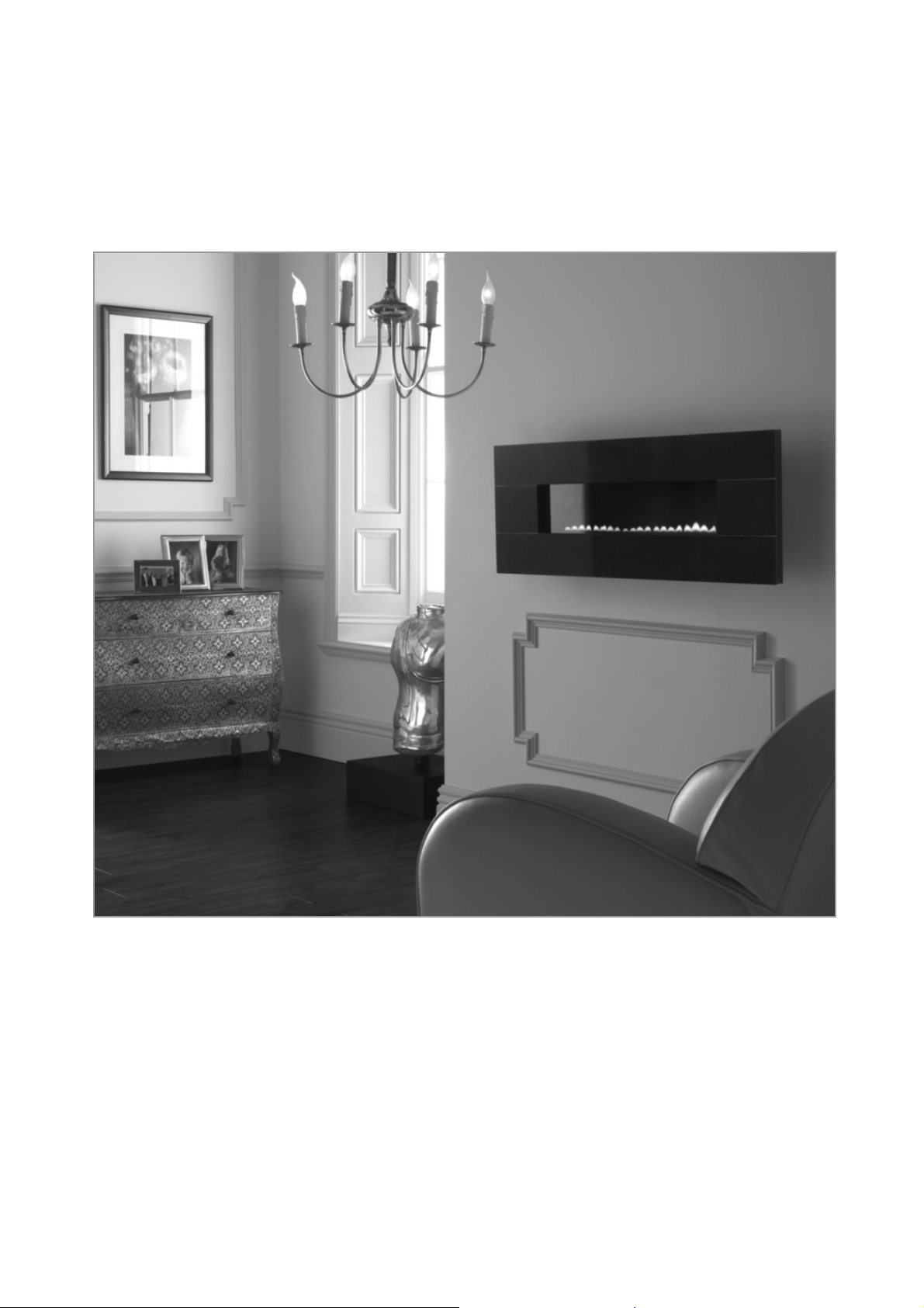
This appliance is designed to be wall-hung. Do not recess any part of the appliance into the wall.
This appliance may be installed in any room in the home except bathrooms or bedrooms. The appliance is
designed to be versatile, and as such will operate correctly when exposed to normal gentle draughts experienced
within the home. It is not recommended, however that the appliance be installed in areas where it is likely to be
directly exposed to persistent strong draughts, that may be generated by outside doors, windows, air vents, air
conditioning units, extractor fans, ceiling fans etc. See section 4.1 for more information on ventilation.
2
2.0
3.0
3.1
4.0
© 2011 Focal Point Fires plc.
APPLIANCE DATA
Natural gas models
Gas Group G20 Natural Gas CAT I2H
Inlet Pressure 20 mbar (+/- 2.0mbar)
Regulator Pressure N/A
Max Energy Input Gross 2.6 kW
Net 2.35 kW
Max Gas Rate 0.25 m3/h
Min Energy Input Gross 1.5 kW
Net 1.35 kW
Pilot Energy Input Gross 166 W
Net 150 W
Operating pressure 20 mbar. (±2.0 mbar)
Main burner flow restrictor Stereo 1.18mm (1/4” BSP)
Oxypilot SIT/Bray 9082
Gas Inlet Connection 8mm inlet restrictor elbow
Ignition Piezo spark
Spark Gap 3.5 - 4.5mm
Please see Data Badge affixed to appliance for current data.
This appliance is for use only with the gas type, and at the pressure stated on the appliance Data Badge.
 Loading...