

Ekofires 3010, 3020, 3015, 3025, EKO 3010 Installation & User's Instructions
...
INSTALLATION & USER INSTRUCTIONS
All instructions must be handed to the user for
safekeeping.
RADIANT/CONVECTOR INSET GAS FIRE
Please note : Except where otherwise stated, all rights, including
copyright in the text, images and layout of this booklet is owned by
Focal Point Fires plc. You are not permitted to copy or adapt any of
the content without the prior written permission of Focal Point Fires
plc.
1
Revision F - 03/13
© 2013 Focal Point Fires plc.
GB IE
BS 7977-1 : 2009
BS EN 509 : 2000
KM579168
IN THE UK ALWAYS USE A GAS SAFE REGISTERED ENGINEER TO INSTALL, REPAIR OR SERVICE THIS APPLIANCE
MODEL SHOWN: EKO 3020
Christchurch, Dorset BH23 2BT
Tel: 01202 588 638
Fax: 01202 499 639
www.ekofires.co.uk
e-mail: sales@ekofires.co.uk
PL EASE NOTE: EKO 3010 , 3015, 302 0, 3025 GAS FIRE S MAY BE SUPPLIE D WITH DIF FE RENT FRET &
FR AMES THAN SHOWN
MODELS COVERED BY THESE INSTRUCTIONS
3010, 3015, 3020 & 3025 GAS FIRES*
*AVAILABLE WITH MANUAL, SLID E CONTROL & REMOTE CONTROL

• This appliance is an Inset Decorative Fuel Effect appliance which provides radiant warmth utilising the latest type
burner technology.
• The fire is designed to suit various types of fireplaces and natural draught flues as detailed in this manual.
• The appliance must be installed by a competent person in accordance with Gas Safety (Installation and Use)
Regulations 1998. It is strongly recommended that a GAS SAFE registered engineer be used for this purpose.
• Read all these instructions before commencing installation.
• This appliance must be installed in accordance with the rules in force and used only in a sufficiently ventilated
space.
• The appliance is designed for installation on to a non-combustible hearth of at least 300mm depth.
• This appliance is factory set for operation on the gas type, and at the pressure stated on the appliance data plate.
• In the event of gas leakage from the appliance, the gas supply must be turned off at the nearest isolating valve.
• The appliance must be installed in accordance with the following:
• Failure to comply with the above could lead to prosecution and deem the manufacturer’s warranty invalid.
• The appliance is designed to fit various types of situations as described in sections 3.0 and 4.0.
• It should be noted that heaters create warm air currents. These currents move heat to wall surfaces next to the
heater. Installing the heater next to vinyl or cloth wall coverings or operating the heater where impurities in the air
(such as tobacco smoke, candle smoke etc.) exist, may cause the walls to become discoloured.
• WARNING: The manufacturer of this appliance considers all surfaces as working surfaces with the exception of
the control knob(s) and ash pan door.
• As with any gas fire, a fire guard complying with BS 8423 must be used in presence of pets, children,
and the elderly or infirm.
• Consult ALL instructions before installation and use of this appliance.
• This appliance is free from any asbestos material.
• Refractories and fuel bed are constructed from ceramic fibre.
• Remote control models : These appliances features a battery-operated control system, and under normal usage
will need a new battery approximately every twelve months.
Refer to the appropriate section of these instructions for details of how to change the battery.
I N S T A L L A T I O N I N S T R U C T I O N S
2
GB IE
• Manufacturers' Instructions.
• The Building Regulations issued by the Department for Communities and Local Government, the Building Standards
(Scotland)
(Consolidation) Regulations issued by the Scottish Development Department.
• Relevant British Standards insofar as the relevant areas are not covered by these instructions.
• For Republic of Ireland, reference should be made to the current edition of IS813 (the relevant standards governing
installation).
1.0 IMPORTANT NOTES
© 2013 Focal Point Fires plc.
Section
1.0
2.0
3.0
4.0
4.1
5.0
6.0
7.0
7.1
8.0
9.0
10.0
11.0
12.0
13.0
14.0
15.0
Contents
Important Notes
Appliance Data
Installation Requirements
Site Requirements
Debris Collection Space
Ventilation
Pre-Fabricated Flue Boxes
Unpacking the Appliance
Component Checklist
Preparing the Appliance
Preparing the Opening
Gas Supply Routing
Installation by Cable Fixing Kit
Fitting the Burner
Gas Connection
Fuel Bed Layout
Fitting the Firefront / Frame
Page No.
2
3
3
3
4
5
5
5
5
6
6
7
7
7
8
8
8
Section
16.0
16.1
16.2
16.3
16.4
16.5
16.6
16.7
16.8
17.0
17.1
17.2
17.3
17.4
17.5
17.6
17.7
18.0
Contents
Testing and Commissioning
Operating the Fire (Manual control)
Operating the Fire (Remote control)
Operating the Fire (Slide control)
Spark Gap
Operating Pressure
Flue Spillage Monitoring System
Testing for Spillage
Briefing the customer
Servicing
Cleaning the Ceramics
Removing the Burner
Dismantling the Burner
Pilot Assembly
Removing the Firebox
Replacing the Batteries
(
Remote control versions)
Replacing the Batteries (Slide control versions)
Troubleshooting Guide
Page No.
8
8
8
9
9
9
9
10
10
10
11
11
11
11
11
11
11
12
2.0 APPLIANCE DATA
3
Model
Destination
Country
Cat
Operating Pressure
(±2.0 mbar)
Max Energy Input (kW) Min Energy Input (kW)
Natural Gas G20 G25
G30 G31 Gross Net Gross Net
Manual control GB - IE
I
2H
20 - - - 6.2 5.6 3.5 3.15
Remote control GB - IE
I
2H
17.5 -
- - 6.2 5.6 3.5 3.15
Slide control GB - IE
I
2H
20 -
- - 6.2 5.6 3.5 3.15
GB IE
3.0 INSTALLATION REQUIREMENTS
Specifications Manual Control Models Remote Control Models Slide Control Models
Main burner injector Stereo size 78 Stereo size 78 Stereo size 78
Oxypilot SIT 9090 SIT 9090 SIT 9090
Gas Control Copreci 21400 Series Mertik Maxitrol GV34 Series Teddington TESA 3173/011
Gas Inlet All models - 8mm compression - Inlet restrictor elbow
Ignition Double-action piezo Spark Piezo Spark Piezo Spark
Spark Gap 3.5 - 4.5mm 3.5 - 4.5mm 3.5 - 4.5mm
Flue specification
All models - 225mm x 225mm (9in x 9in) brick or stone.
125mm (5in) minimum diameter lined brick or stone.
125mm (5in) minimum diameter twin wall flue conforming to BS 715.
Pre-cast block flue complying with BS 1289 or BS EN 1858.
This appliance MUST NOT be installed into a room containing a bath or shower, or where steam may be present. The fire has been
designed to fit into a builders’ opening or fireplace conforming to BS 1251 or BS EN 1858 (and meeting certain dimensional requirements), or a suitable flue box complying with the constructional requirements of BS 715. The flue box must be installed onto a suitable
non-combustible insulating surface at least 12mm thick, covering the entire base area of the box.
A natural draught flue system is required, and if previously used for solid fuel or oil burning, the flue and chimney must be swept prior
to appliance installation. The flue must have an effective height of at least three metres, as measured from the hearth to the top of the
flue. Any flue damper plates or restrictors should be removed and no other restriction fitted to the flue. Where removal is not practical, the restriction must be fixed in the fully open position. The flue must be checked before installation by using a smoke pellet or similar to ensure proper draw and that leakage is not evident at any joints. Repair and re-test as necessary before the appliance is installed.
The flue must be connected to only one fireplace, and the flue must not vent more than one appliance (i.e. not shared with a gas back
boiler). There must be no opening in the flue apart from the one that the appliance is installed into, and the one venting the gases into
the air. A suitable terminal may be fitted, such as class GC1, as regulations allow.
This appliance has been tested for use in a pre-cast block flue complying with BS 1289 or BS EN 1858. In accordance with BS 1289 part
1, pre-cast flues built with directly plastered faces (front or rear) are not correctly installed as to ensure proper operation with any type
of gas fire. In some instances of this flue construction, temperature cracking of the surface plaster may occur through no fault of the
appliance. An air gap or some form of insulation material should be installed to prevent normal flue temperatures from damaging wall
surfaces. Pre-cast flues must be checked for mortar fangs and correct installation of joints, flue sections in loft space and terminals.
This appliance has been tested for use with circular flues of a minimum internal diameter of 125mm.This appliance is suitable for use
with a “lightweight” surround and back panel of 150°C minimum rating.
The fireplace opening should be inspected and repairs made where necessary. Any chair brick or fireback may be left insitu, providing
that the dimensional requirements for debris collection space and spigot clearances are met. See figure 1.
The opening WIDTH and HEIGHT dimensions should be between 350mm and 450mm wide, and 540mm to 575mm high. For flues used
with solid fuel, the minimum WIDTH is 380mm.
Opening DEPTH should be 200mm or greater for a clay/cement lined or Pre-cast flue which is new, unused, or previously used only with
a gas appliance. DEPTH should be 240mm or greater for a flue used for solid fuel of oil burning appliances. Opening DEPTHS include
any plaster or infill panels which form part of the installation.
4.0 SITE REQUIREMENTS
Please see Data Badge affixed to appliance for current data. This appliance is for use only with the gas type, and at the pressure stated
on the appliance Data Badge, and is for decorative purposes.
© 2013 Focal Point Fires plc.
4.0 SITE REQUIREMENTS - CONTINUED
GB IE
4
All models : This appliance requires a natural draught flue system which may be one of the following;
225mm x 225mm (9in x 9in) brick or stone.
125mm (5in) minimum diameter lined brick or stone.
125mm (5in) minimum diameter twin wall flue conforming to BS 715.
Pre-cast block flue complying with BS 1289 or BS EN 1858.
Any existing under grate draught device must be sealed off. The opening wall must be non-combustible.
The appliance requires a hearth with non-combustible surface of at least 12mm thick. The top surface must be at least 50mm above the
surrounding floor level, or be surrounded by a raised edge or fender 50mm high.
To enable the products of combustion to be cleared properly up the flue, the outlet at the back of the appliance must have a 50mm minimum clearance between it and the back wall of the opening or any other obstruction. The area immediately above the outlet must form
a smooth path into the flue.
Any type of fire surround used with this appliance must be adequately sealed to the wall and floor.
A combustible shelf may be fixed to the wall above the fire, providing that it complies with the dimensions given below.
A non-combustible shelf may be fitted to within 10mm of the top edge of the fireframe. Combustible materials, such as wood, may be
fitted to within 100mm of either side of the fireplace opening, providing the forward projection does not exceed 100mm. Any combustible side walls must be at least 500mm to the side of the radiant heat source. As with all heating appliances, any decorations, soft
furnishings, and wall coverings (i.e. flock, blown vinyl and embossed paper) positioned too close to the appliance may discolour or scorch.
The mounting depth of this appliance is 108mm (120mm - Convector models).
In accordance with BS 5871 part 2, minimum debris collection volumes are required behind the installed appliance. These are shown
below and as dimension ‘X’ in figure 1.
CLAY/CEMENT LINES OR BLOCK FLUE WHICH IS NEW, UNUSED, OR PREVIOUSLY ONLY USED WITH A GAS FIRE.
X Dimension = 20mm
UNLINED FLUE OR CHIMNEY WHICH HAS BEEN PREVIOUSLY USED FOR A SOLID FUEL OR OIL BURNING APPLIANCE
X Dimension = 60mm
4.1 DEBRIS COLLECTION SPACE
© 2013 Focal Point Fires plc.
Maximum depth of shelf
Minimum distance from finished
hearth surface to underside of shelf
100mm (4in) 745mm (29
1/4
in)
150mm (6in) 845mm (33
1/4
in)
203mm (8in) 895mm (35
1/4
in)
Note : Italics refer to Convector models.
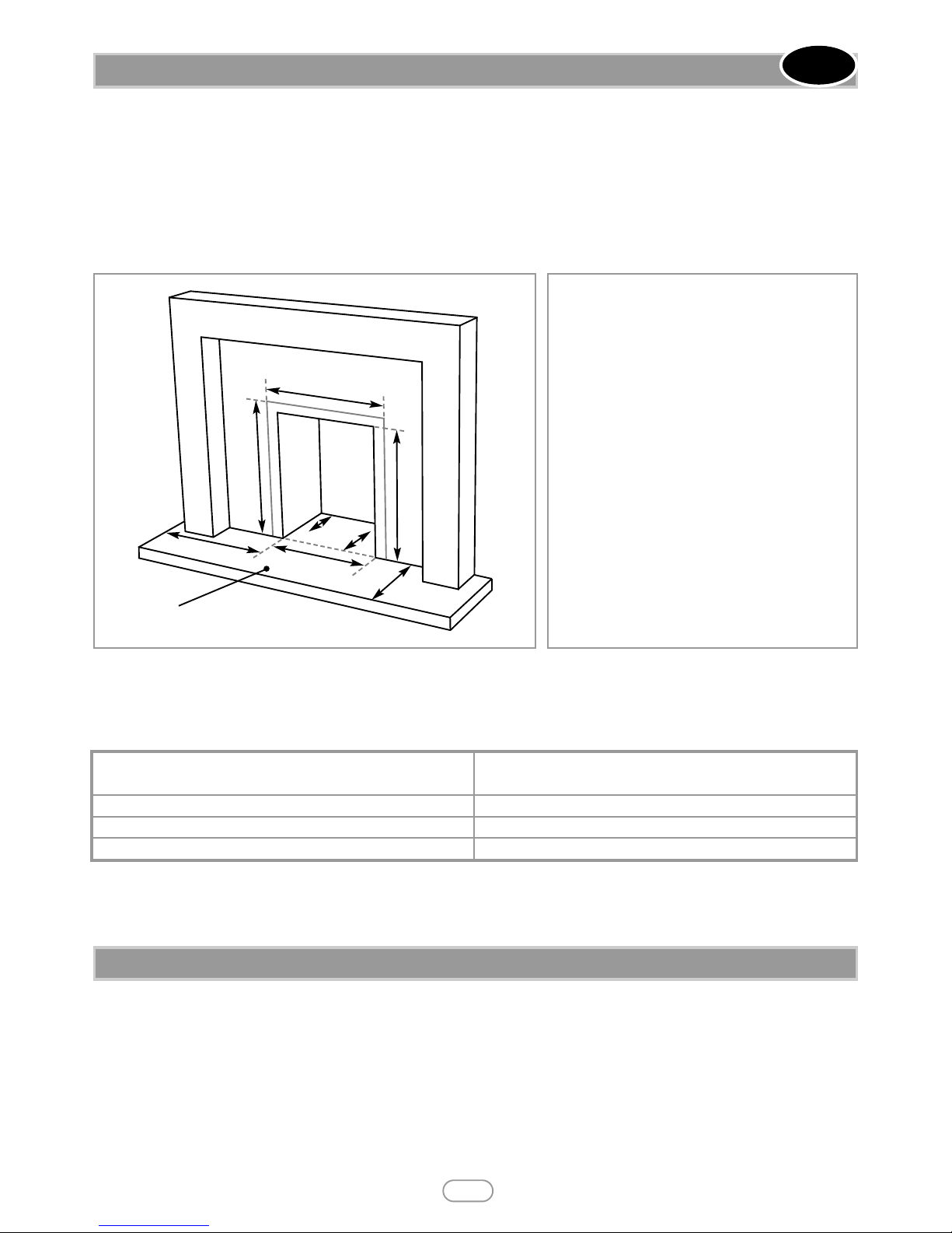
‘A’. Opening height: 540mm min/575mm max.
‘B’. Opening width: 350mm min/440mm max.
(380mm min/440mm max.)
‘C’. Mounting depth: 108mm (125mm).
‘D’. Hearth must extend minimum of 150mm either
side of the opening.
‘E’. Hearth must extend minimum of 300mm in front
of the opening.
‘F’. Non-combustible hearth must be a minimum of
50mm in height, or be surrounded by 50mm high
fender.
‘G’. 470mm, this area must be flat and vertical to
ensure a good seal.
‘H’. 585mm, this area must be flat and vertical to
ensure a good seal.
‘X’. Debris collection space - See section 4.1.
‘A’
‘C’
‘B’
‘E’
‘F’
‘G’
‘H’
‘X’
‘D’
Figure 1
No purpose provided ventilation is normally required for this appliance. The requirements of other appliances operating in the
same room or space must be taken into consideration when assessing ventilation. If spillage is detected when commissioning the appliance, then amongst other problems there may be insufficient natural ventilation for correct operation of the flue. If the appliance does
not spill with the windows open, but spillage is detected with the windows closed, this demonstrates a lack of natural ventilation. If
spillage is still detected with the windows open, the flue is at fault. Installation of an air brick is the best solution to lack of ventilation.
Any ventilation fitted must comply with BS 5871 part 2 and BS 5440 part 2. Vents fitted under or within the immediate vicinity of the
appliance must not be used as adverse effects to the operation of the ODS may occur. Spillage detected during commissioning is almost
always a result of poor flue performance that cannot be corrected by any amount of ventilation. For Republic of Ireland ventilation may
be required, see IS 813, ICP3, IS 327, and any other rules in force.
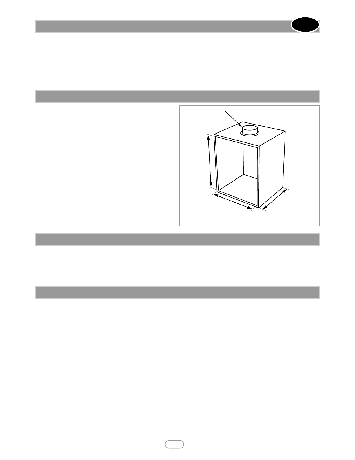
This appliance can be fitted into a number of proprietary flue
boxes provided that the minimum dimensions shown in figure 2
are complied with.
Constructional Note: The frame of the fire, any back panel or
other infill panels, and the flue box must be sealed together so that
there is no possibility of leakage between them. Adequate clearances to combustible materials (e.g. false chimney breast construction) must be maintained.
The manufacturers’ instructions for fitting the prefabricated box shall be complied with at all times. To fit the fire
using the cable fixing kit, some minor adaption may be necessary
for certain flue boxes. A check should be made to ensure the firebox does not obscure the flue box outlet. The firebox, base of the
flue box, and hearth below may be drilled to allow plugs and
screws to secure installation. It is important that the sealing
requirements of the appliance are met at all times and that the flue
box is well sealed to any back or infill panel. Note: The DEPTH
dimension is inclusive of any back or infill panel.
Stand the carton the right way up, cut the strapping bands and remove the top endcap. Read all the instructions before continuing to
unpack or install this appliance. Remove the box containing the firefront, and the bags containing the ceramic components. Remove the
cardboard packing pieces, and any other bags or boxes containing fittings or other parts. When all loose parts have been removed, the
outer sleeve may be lifted off to reveal the appliance. Check that the components supplied correlate with the component checklist given
in section 7.1. Please dispose of all the packaging materials at your local recycling centre.
5.0 VENTILATION
GB IE
6.0 PREFABRICATED FLUE BOXES
125mm min internal dia. twin wall flue
Radiant models:
125mm min
depth
Convector
models:
140mm min
depth
Radiant models: 350mm min opening width
Convector models: 380mm min opening width
540mm
min height
Figure 2
7.0 UNPACKING THE APPLIANCE
7.1 COMPONENT CHECKLIST
QUANTITY DESCRIPTION
1 Firebox and burner tray assembly
1 Decorative frame
1 Firefront
1 Black Moulded ceramic fibre combustion matrix (coal effect versions only)
1 Beige Moulded ceramic fibre combustion matrix (Pebble effect version only)
11 Individual ceramic coals (rounded coal effect version only)
15 Individual ceramic coals (ripped coal effect version only)
15 Individual ceramic pebbles (pebble effect version only)
2 Ceramic fibre side cheeks (pebble effect & ripped coal effect)
1 Ceramic rear panel
1 Ceramic taper pad (radiant models only)
1 Remote control handset (remote control models only)
1 Cable fixing kit; 2 cables, 2 tensioners, 2 cable clamps, 4 fixing eyes, 4 wall plugs
1 Sealing grommet
3 Lengths of adhesive sealing strip
1 Self tapping screw pack; 4 No.8 x 5/16
1 Spigot restrictor
1 Deflector baffle
1 Set of manufacturers instructions
1 Slide control position marking sticker (slide control models only)
1 Slide control knob and M4 Nyloc nut (slide control models only)
5
© 2013 Focal Point Fires plc.
Note: Ensure that the gas supply is isolated before commencing installation of the appliance.
The fireplace opening and environment must be in compliance with specifications
laid down in the appropriate sections of these instructions. Remove the appliance
from the carton as described previously and stand on a dust sheet or similar. Place
the coals/pebbles, ceramics and fixings safely to one side. Remove the burner from
the assembly by removing the two screws retaining the tray legs. The tray is now free
and may be lifted away.
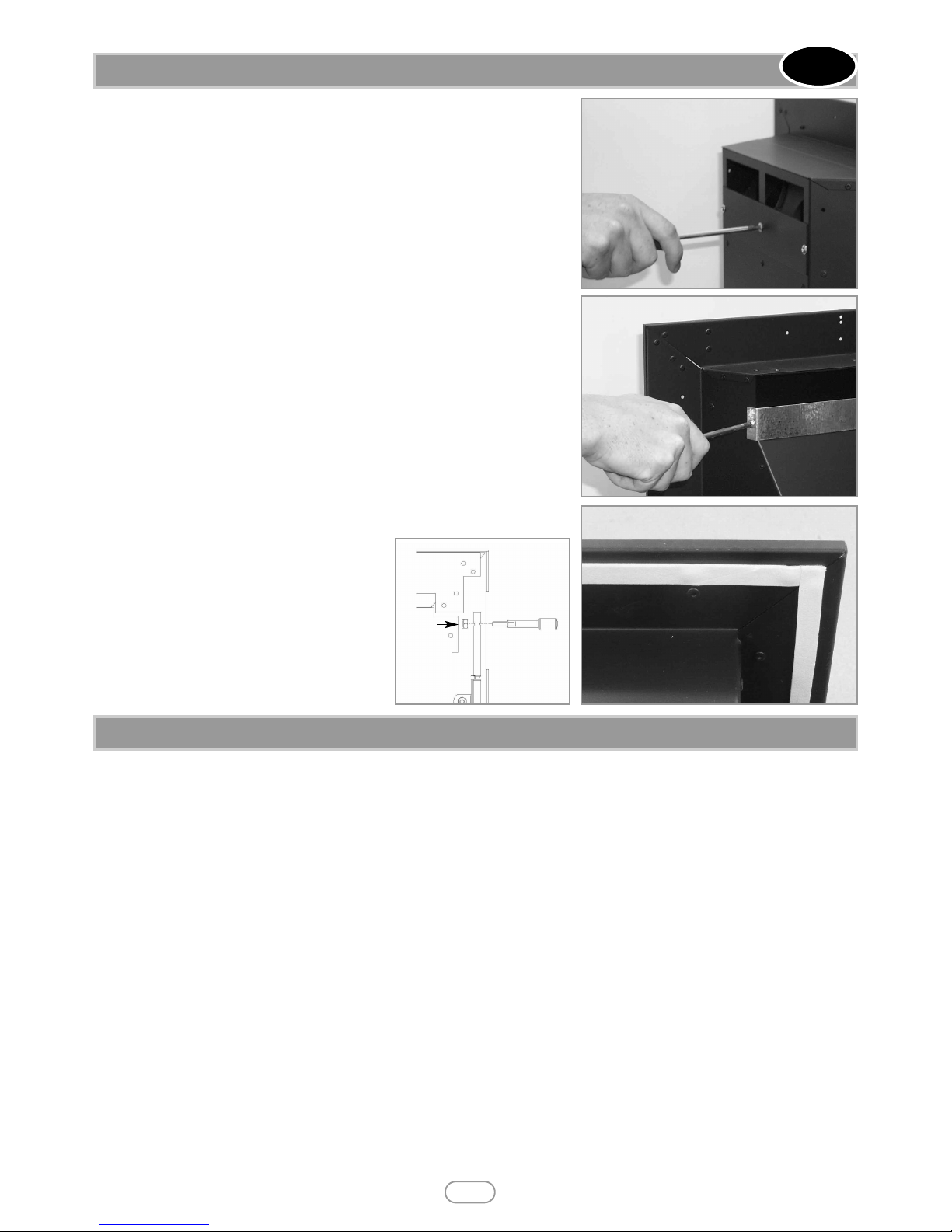
SPIGOT RESTRICTOR :
If fitting the fire into a Class 1 or good Class 2 flue, attach the spigot restrictor to
the rear of the appliance using screws provided as shown in figures 3 and 4. If spillage
is detected during the commissioning of the appliance, the spigot restrictor should
be removed immediately.
SUPPLY PIPE ENTRY :
Knockout holes are provided in the rear and sides of the firebox for use where concealed pipework is required. Where necessary, knock out the appropriate hole with
a sharp tap from a hammer, and fit the rubber grommet supplied. A small incision can
now be made in the rubber to slip snugly around the outside of the pipe and sleeving. Do not install or use the appliance without the seal in place. If a hole is
inadvertently opened, reseal with an intact grommet. Failure to fit the seal correctly
will cause flue suction to act upon the area under the burner, resulting in poor performance and intermittent cutting out of the burner.
SEALING STRIPS :
Apply the self adhesive sealing strips to the back
of the fireframe as shown in figure 5 to give a
continuous seal.
SLIDE CONTROL MODELS : The control
knob is supplied as a loose part. Insert the control
knob into the hole in the top of the slide control
spindle (Figure 6). Secure the control knob in position using the M4 nyloc nut provided. Affix the Slide
control position marking sticker on the trim next
to the control knob as shown in figure 16.
Before installing the fire, check the flue using a smoke pellet. All of the smoke should travel up the flue and exit correctly from the terminal.
If problems are found, DO NOT fit the fire until corrective action is completed. Protect the decorative hearth whilst pushing the firebox in and out of the opening. Part of the packaging will make an ideal hearth saver pad. Before running the gas supply into the opening, offer up the firebox to the fireplace to check the fit is good.
Ensure that it slides in correctly, the sealing face sits flat and square to the wall or infill panel, and that the base is firm on the floor of
the opening as no leaks are permissible here. At this stage it is essential to ensure that the spigot outlet of the fire is not restricted in
any way. Remove the firebox and take any necessary measurements before making good and preparing for final installation.
CABLE FIXING :
For fixing of the fire by the cable method, see the relevant section. The cable fixing locations should be marked on the back of the opening and the holes drilled. Fit the wall plugs and eyebolts to these holes.
SCREW FIXING :
For fixing by screw, mark and drill the fireframe or base, and the relevant points in the opening or on the wall. wall plugs will again be
required. Pre-punched holes are not provided for this purpose to allow you to choose the optimum positions.
GAS SUPPLY :
Following preparation for the fixing method, the concealed gas supply, where required, can now be put into place. Refer to the gas supply section for suggested pipe routes. The ends of the sleeving in which the gas pipe is run should be sealed. The ends of the 8mm supply pipe should be temporarily sealed to prevent the ingress of debris during fixing.
PLEASE NOTE: Ensure fire can be removed for ease of servicing and not silconed
8.0 PREPARING THE APPLIANCE
GB IE
6
© 2013 Focal Point Fires plc.
Figure 5
Figure 3 - Convector models
Figure 4 - Radiant models
9.0 PREPARING THE OPENING
Figure 6
 Loading...