

Ekofires 8010, 8020 Installation & User's Instructions
INSTALLATION & USER INSTRUCTIONS
All instructions must be handed to the user
for safekeeping.
WALL INSET GAS FIRES
Revision A - 05/17
© 2017 Focal Point Fires plc
GB IE
1
Please note : Except where otherwise stated, all rights,
including copyright in the text, images and layout of this
booklet is owned by Focal Point Fires plc. You are not permitted to copy or adapt any of the content without the
prior written permission of Focal Point Fires plc.
IN THE UK ALWAYS USE A GAS SAFE REGISTERED ENGINEER TO INSTALL, REPAIR OR SERVICE THIS APPLIANCE
MODEL SHOWN : EKO 8010 WALL INSET GAS FIRE
MODELS COVERED BY THESE INSTRUCTIONS
8010 WALL INSET GAS FIRE
8020 WIDE WALL INSET GAS FIRE
A
VAILABLE IN SLIDE CONTROL & REMOTE CONTROL
Christchurch, Dorset BH23 2BT
Tel: 01202 588 638
Fax: 01202 499 639
www.ekofires.co.uk
e-mail: sales@ekofires.co.uk

• This appliance is an Inset Decorative Fuel Effect appliance which provides radiant warmth utilising the latest type burner technology.
• The fire is designed to suit various types of fireplaces and natural draught flues as detailed in this manual.
• The appliance must be installed by a competent person in accordance with Gas Safety (Installation and Use) Regulations 1998. It is
strongly recommended that a GAS SAFE registered engineer be used for this purpose.
• Read all these instructions before commencing installation.
• This appliance must be installed in accordance with the rules in force and used only in a sufficiently ventilated space.
• This appliance is factory set for operation on the gas type, and at the pressure stated on the appliance data plate.
• In the event of gas leakage from the appliance, the gas supply must be turned off at the nearest isolating valve.
• The appliance must be installed in accordance with the following:
• Failure to comply with the above could lead to prosecution and deem the manufacturer’s warranty invalid.
• The appliance is designed to fit various types of situations as described in sections 3.0 and 4.0.
• It should be noted that heaters create warm air currents. These currents move heat to wall surfaces next to the heater. Installing the
heater next to vinyl or cloth wall coverings or operating the heater where impurities in the air (such as tobacco smoke, candle smoke
etc.) exist, may cause the walls to become discoloured.
• WARNING: The manufacturer of this appliance considers all surfaces as working surfaces with the exception of the control knob
• As with any gas fire, a fire guard complying with BS 8423 must be used in presence of pets, children, and the elderly or infirm.
• Consult ALL instructions before installation and use of this appliance.
• This appliance is free from any asbestos material.
• Refractories and fuel bed are constructed from ceramic fibre.
• Slide control models : These appliances feature a battery-operated control system, and under normal usage will need a new battery
approximately every twelve months.
Burner/spark generator requirements - 1 x AA (1.5 volt)
Refer to the appropriate section of these instructions for details of how to change the battery.
• Remote control models : This appliance features a battery-operated remote control system, and under normal usage will need
new batteries approximately every twelve months.
Remote control Handset requirements - 1 x ‘PP3’ type (9 volt)
Receiver/motor unit requirements - 4 x ‘AA’ type (1.5 volt)
Refer to the appropriate section of these instructions for details of how to change the batteries.
I N S T A L L A T I O N I N S T R U C T I O N S
2
GB IE
• Manufacturers' Instructions.
• The Building Regulations issued by the Department for Communities and Local Government, the Building Standards (Scotland)
(Consolidation) Regulations issued by the Scottish Development Department.
• Relevant British Standards insofar as the relevant areas are not covered by these instructions.
• For Republic of Ireland, reference should be made to the current edition of IS813 (the relevant standards governing installation).
Section
1.0
2.0
3.0
4.0
4.1
5.0
6.0
6.1
7.0
7.1
7.2
7.3
7.4
7.5
7.6
8.0
8.1
8.2
Contents
Important Notes
Appliance Data
Installation Requirements
Site Requirements
Debris Collection Space
Ventilation
Unpacking the Appliance
Component Checklist
Preparing the Appliance
Preparing the Opening
Gas Supply Routing
Installing the Firebox
Installing the Ceramic Tiles
Installing the Burner
Gas Connection
Testing and Commissioning
Spark Gap
Installing the Ceramics
Page No.
2
3
3
3
4
5
5
5
5
6
6
7
7
8
8
8
8
8
Section
8.3
8.4
8.5
8.6
8.7
8.8
8.9
9.0
10.0
10.1
10.2
10.3
10.4
10.5
10.6
10.7
11.0
11.1
Contents
Assembling the Appliance
Operating the Appliance
Operating Pressure - M
anual, Slide & Remote Controls
Flue Spillage Monitoring System
Testing for Spillage
Final Assembly
Fitting the Decorative Frame Assembly
Briefing the Customer
Servicing
Cleaning the Ceramics
Removing the Burner
Servicing the Burner
Pilot Assembly
Removing the Firebox
Replacing the Batteries-
Remote Controls
Replacing the Batteries- S
lide Controls
Troubleshooting Guide
Troubleshooting Guide- Remote Controls
Page No.
8
9
9
9
9
10
10
10
11
11
11
11
11
12
12
12
12
13
1.0 IMPORTANT NOTES
© 2017 Focal Point Fires plc.
These appliances have been tested for use with circular flues of a minimum internal diameter of 125mm. The fireplace opening should
be inspected and repairs made where necessary.
All models : This appliance requires a natural draught flue system which may be one of the following;
125mm (5in) minimum diameter flexible flue liner.
125mm (5in) minimum diameter twin wall flue conforming to BS 715.
2.0 APPLIANCE DATA
3
GB IE
4.0 SITE REQUIREMENTS
Please see Data Badge affixed to appliance for current data. This appliance is for use only with the gas type, and at the pressure stated
on the appliance Data Badge, and is for decorative purposes.
© 2017 Focal Point Fires plc.
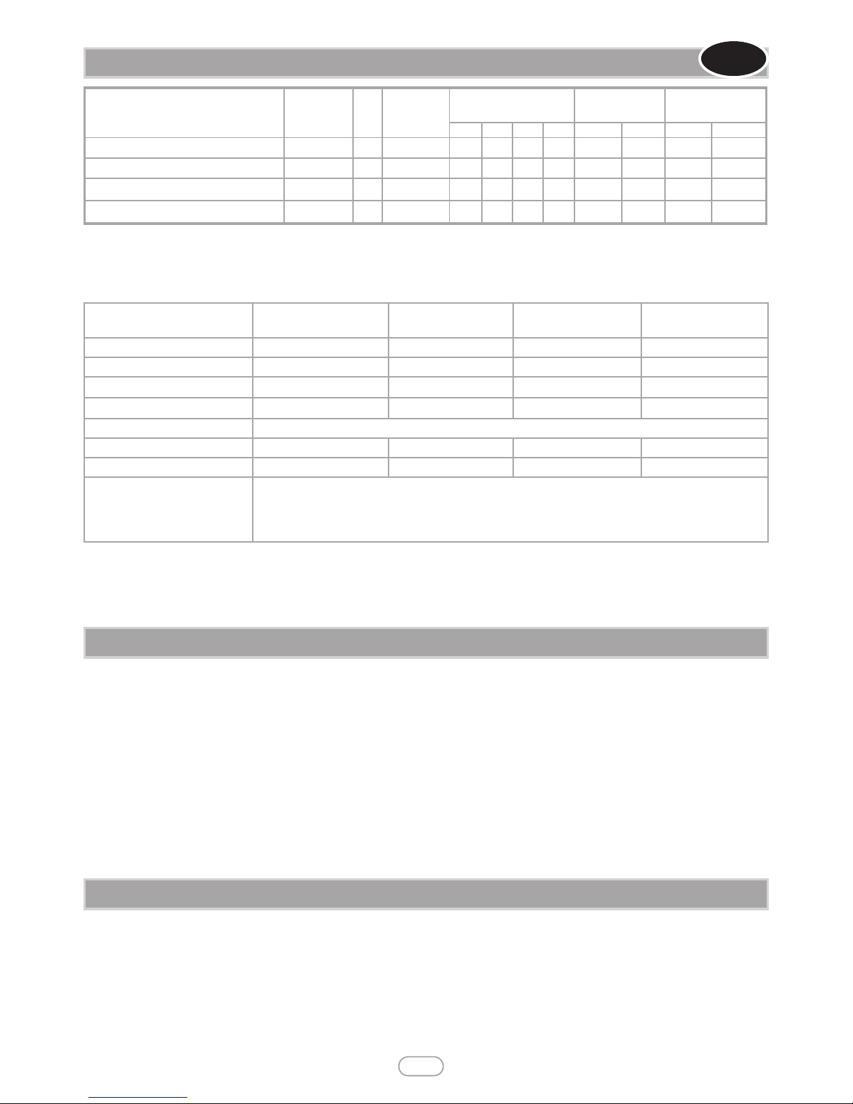
Specifications
Wall inset slide control
models
Wall inset remote
control models
Wide wall inset slide
control models
Wide wall inset remote
control models
Efficiency 70% (net), 63% (gross)
70% (net), 63% (gross)
70% (net), 63% (gross) 70% (net), 63% (gross)
Main burner injector Stereo size 1.47 Stereo size 1.44 Stereo size 1.53 Stereo size 1.50
Oxypilot Copreci 21100 2F/297
Copreci 21100 2F/297
Copreci 21100 2F/297 Copreci 21100 2F/297
Gas Control Teddington TESA 3173/011
Mertik Maxitrol GV60 series
Teddington TESA 3173/011
Mertik Maxitrol GV60 series
Gas Inlet All models - 8mm compression - Inlet restrictor elbow
Ignition Battery Spark
Battery Spark
Battery Spark Battery Spark
Spark Gap
3.5 - 4.5mm
3.5 - 4.5mm
3.5 - 4.5mm 3.5 - 4.5mm
Flue specification
125mm (5in) minimum diameter flexible flue liner.
125mm (5in) minimum diameter twin wall flue conforming to BS 715.
3.0 INSTALLATION REQUIREMENTS
This appliance MUST NOT be installed into a room containing a bath or shower, or where steam may be present. The fire has been
designed to fit into a builders’ opening or fireplace conforming to BS 1251 (and meeting certain dimensional requirements), which has
been lined with a 125mm diameter flexible flue liner.The firebox must be installed onto a suitable non-combustible insulating surface at
least 12mm thick, covering the entire base area of the firebox. The flue must have an effective height of at least three metres, as measured from the bottom of the appliance to the top of the flue. Any flue damper plates or restrictors should be removed and no other
restriction fitted to the flue. Where removal is not practical, the restriction must be fixed in the fully open position.
The fire is suitable for twin wall 125mm diameter flue and flue liner which fits directly on to the appliance. If previously used for solid
fuel or oil burning, the flue and chimney must be swept prior to appliance installation. The flue must be checked before installation by
using a smoke pellet or similar to ensure proper draw and that leakage is not evident at any joints. Repair and re-test as necessary before
the appliance is installed. The flue must be connected to only one fireplace, and the flue must not vent more than one appliance (i.e. not
shared with a gas back boiler). There must be no opening in the flue apart from the one that the appliance is installed into, and the one
venting the gases into the air. A suitable terminal may be fitted, such as class GC1, as regulations allow.
Model
Country of
Destination
Cat Gas Type
Operating Pressure
(±2.0 mbar)
Max Energy
Input (kW)
Min Energy Input
(kW)
G20 G25 G30 G31 Gross Net Gross Net
Wall inset slide control models GB - IE
I
2H
Natural Gas 20 -
- - 3.8 3.4 2.0 1.8
Wall inset remote control models GB - IE
I
2H
Natural Gas 20 -
- - 3.8 3.4 2.0 1.8
Wide wall inset slide control models GB - IE
I
2H
Natural Gas 20 -
- - 4.4 4.0 2.2 2.0
Wide wall inset remote control models GB - IE
I
2H
Natural Gas 20 -
- - 4.4 4.0 2.2 2.0
The efficiency of this appliance has been measured as specified in BS 7977-1:2009 +A1:2013 and the result is 63%. The gross calorific
value of the fuel has been used for this efficiency calculation. The test data from which it has been calculated has been certified by bsi
(0086). The efficiency value may be used in the UK Government’s Standard Assessment Procedure (SAP) for energy rating of
dwellings.
4.0 SITE REQUIREMENTS - CONTINUED
GB IE
4
Whilst a hearth is not required under regulations, it may be adviserable to fit a hearth as a tactile barrel against “walk on” or clothes
drying.
Any existing under grate draught device must be sealed off. The fireplace wall must be non-combustible.
A combustible shelf may be fixed to the wall above the fire, providing that it complies with the dimensions given below.
A non-combustible shelf may be fitted to within 10mm of the top edge of the fireframe. Combustible materials, such as wood, may be
fitted to within 100mm of either side of the fireplace opening, providing the forward projection does not exceed 100mm. Any combustible side walls must be at least 500mm to the side of the radiant heat source. As with all heating appliances, any decorations, soft
furnishings, and wall coverings (i.e. flock, blown vinyl and embossed paper) positioned too close to the appliance may discolour or scorch.
The wall for 300mm above the fireplace must be of a non combustible material able to withstand 120°C. Such as calcium silicate board, brick or stone.
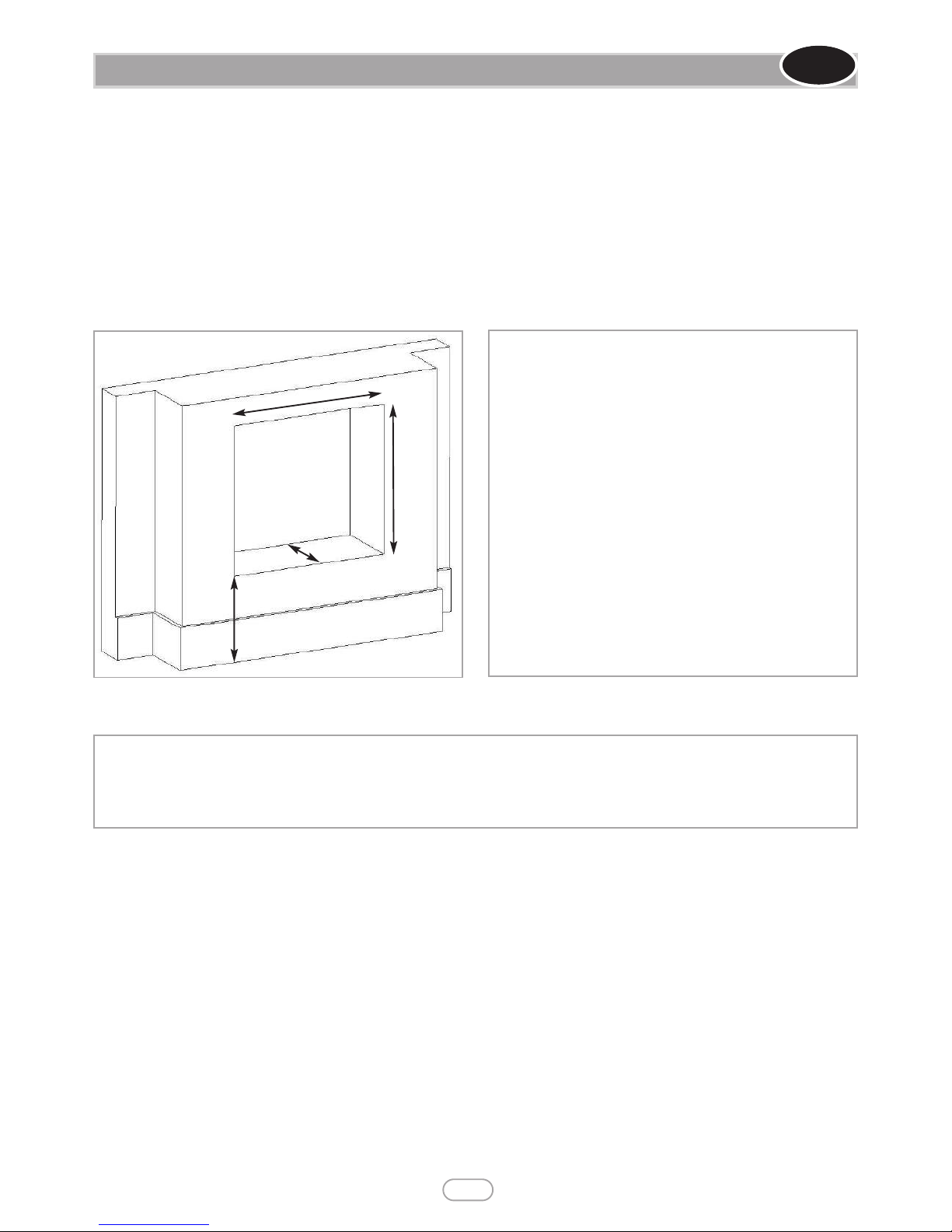
Note: dimensions in italics refer only to wide wall inset
models.
‘A’. Opening height: 530mm - 535mm.
‘B’. Opening width: 567mm min/587mm max. (867mm
min/887mm max).
‘C’. Mounting depth: minimum 250mm.
‘D’. The distance from the floor must be 100mm or greater.
Maximum depth of shelf Minimum distance from bottom of the appliance
surface to underside of shelf
100mm 745mm
150mm 845mm
203mm 895mm
© 2017 Focal Point Fires plc.
‘A’
‘B’
‘C’
‘D’
Figure 1
Note: Ensure that the gas supply is isolated before commencing installation of the appliance.
The fireplace opening and environment must
be in compliance with specifications laid down
in the appropriate sections of these instruc-
tions.
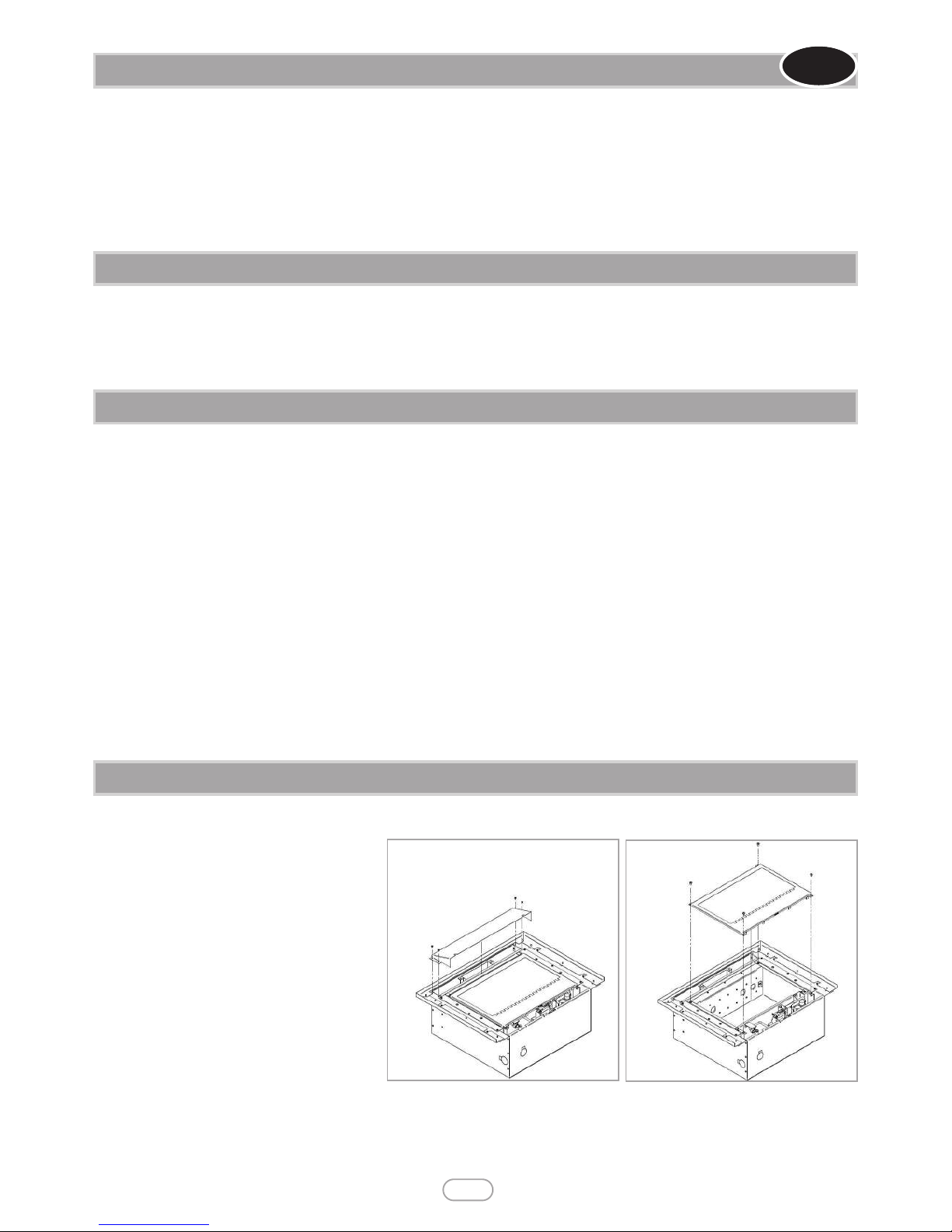
Remove the appliance from it’s carton as
described previously and lay the appliance on
its back, on a dust sheet or similar. Place the
decorative frame, logs, ceramics and fixings
safely to one side. Remove the hood from the
assembly by removing the retaining screws
either side of the hood. See figure 2.
Next, remove the glass assembly by unscrewing the screws in each of the corners.
No purpose provided ventilation is normally required for this appliance. The requirements of other appliances operating in the
same room or space must be taken into consideration when assessing ventilation. If spillage is detected when commissioning the appliance, then amongst other problems there may be insufficient natural ventilation for correct operation of the flue. If the appliance does
not spill with the windows open, but spillage is detected with the windows closed, this demonstrates a lack of natural ventilation. If
spillage is still detected with the windows open, the flue is at fault. Installation of an air brick is the best solution to lack of ventilation.
Any ventilation fitted must comply with BS 5871 part 2 and BS 5440 part 2. Vents fitted under or within the immediate vicinity of the
appliance must not be used as adverse effects to the operation of the ODS may occur. Spillage detected during commissioning is almost
always a result of poor flue performance that cannot be corrected by any amount of ventilation. For Republic of Ireland ventilation may
be required, see IS 813, ICP3, IS 327, and any other rules in force.
5.0 VENTILATION
GB IE
6.0 UNPACKING THE APPLIANCE
6.1 COMPONENT CHECKLIST
QUANTITY DESCRIPTION
1 Firebox and burner tray assembly
1 Decorative frame
1 Flue adapter assembly
3 Individual ceramic logs (Wall inset models only)
10 Individual ceramic logs (Wide wall inset models only)
1 Fixing kit; 4x screws 4x wall plugs
1 Sealing grommet
1 Remote control Handset (Remote control models only)
1 Set of manufacturers instructions
4 M5 screws
1 Tiled ceramic set (2 x side tiles & 1 x back tile)
2 No.8 x 5/16” screws
2 “L” brackets
2 M4 screws
5
© 2017 Focal Point Fires plc.
Remove the outer packaging, remove any instructions. Read ALL these instructions before continuing to unpack or install this appliance.
Lift off the remaining packaging components and remove the contents of the box. Check that the components supplied correlate with
the component checklist. Please dispose of all the packaging materials at your local recycling centre.
7.0 PREPARING THE APPLIANCE
Figure 2 Figure 3
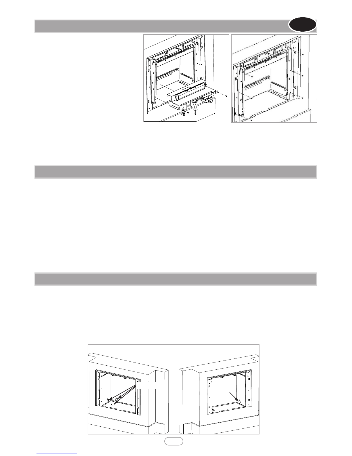
Remove the burner unit by removing the two
screws either side of the burner as shown in
figure 4.
The tray is now free, and may be lifted away.
Remove the internal firebox from the external
firebox via the six screws highlighted in figure 5.
SUPPLY PIPE ENTRY (All models):
Knockout holes are provided in the rear, the
sides and the bottom of the firebox for use
where concealed pipework is required. Where
necessary, knock out the appropriate hole with
a sharp tap from a hammer, and fit the rubber grommet supplied. A small incision can now be made in the rubber to slip snugly
around the outside of the pipe and sleeving. Do not install or use the appliance without the seal in place. If a hole is inad-
vertently opened, reseal with an intact grommet. Failure to fit the seal correctly will cause flue suction to act upon the area under
the burner, resulting in poor performance and intermittent cutting out of the burner.
7.0 PREPARING THE APPLIANCE - CONTINUED
GB IE
6
© 2017 Focal Point Fires plc.
7.1 PREPARING THE OPENING
Before installing the fire, check the flue using a smoke pellet. All of the smoke should travel up the flue and exit correctly from the terminal. If problems are found, DO NOT fit the fire until corrective action is completed. Before running the gas supply into the opening,
offer up the firebox to the fireplace opening to check the fit is good. Ensure that it slides in correctly, the sealing face sits flat and square
to the wall or infill panel, and that the base is firm on the floor of the opening as no leaks are permissible here. At this stage it is essential to ensure that the outlet of the fire is not restricted in any way. Remove the firebox and take any necessary measurements before
making good and preparing for final installation.
SCREW FIXING : For fixing the appliance to the wall, mark and drill the relevant holes in the firebox on the wall. Insert the wall plugs
into the wall. Insert the firebox back into its correct position and fasten the firebox to the wall using the screws provided.
GAS SUPPLY : Following preparation for the fixing method, the concealed gas supply, where required, can now be put into place. Refer
to the gas supply section for suggested pipe routes. The ends of the sleeving in which the gas pipe is run should be sealed. The ends of
the 8mm supply pipe should be temporarily sealed to prevent the ingress of debris during fixing.
PLEASE NOTE: Ensure fire can be removed for ease of servicing and not siliconed.
When the opening is ready for installation of the fire, the gas supply may be routed as per the examples shown in figure 6.
IMPORTANT - Wherever a concealed connection is made a rubber grommet must be used to seal the firebox.
The gas pipe must be suitably protected where it passes through fireplace openings. Any sleeving should be sealed to the pipe at its ends.
This appliance is fitted with an inlet restrictor elbow. Using 8mm diameter pipe, connect the appliance to the gas supply point. The appliance must be fitted with rigid or semi-rigid pipe of 8mm external diameter. The appliance is factory fitted with an inlet restrictor elbow.
Use a minimum length of 8mm pipe, less than 1.5m where possible, as a long run of pipe may cause an unacceptable drop in the supply
pressure.The open end of the supply pipe should be sealed temporarily during the installation of the firebox to prevent the ingress of
dirt and dust. Soldered joints are not recommended.
7.2 GAS SUPPLY ROUTING
Knockouts
Knockout
Figure 4
Figure 6
Figure 5
7
© 2017 Focal Point Fires plc.
7.3 INSTALLING THE FIREBOX
Remove any protective film coatings from the finished/decorative surfaces of the appliance. After having selected the final mounting posi-
tion of the appliance, taking into account the requirements as specified in sections 3 and 4
of these instructions, the integrity of the wall, and the feasibility of the proposed supply pipe
routing, the firebox of the appliance may be secured to the wall.
To ensure customer safety, be sure to design the installation so that the strength of both
the wall and any wall fixings used are sufficient.
Focal Point Fires plc. assumes absolutely no responsibility for injuries and/or damages that
may occur due to improper installation or handling. The appliance should not be installed
until all wet plastering and/or dry wall sanding and wall painting has been completed. Do
not block the ventilation holes of the appliance.
The wall onto which the appliance is installed must be flat. Install only on a vertical surface.
Avoid sloped surfaces. Installation onto anything other than a vertical wall may result in fire,
damage or injury. If the appliance is to be mounted on the inner leaf of a conventional cavity brick wall, or a solid wall, then the wall
plugs and fixing screws provided may be used. Depending on the condition of the wall it may be necessary to use additional fixings. In
this situation, any additional fixings and wall plugs should be of the same size and type as the ones provided. At the appropriate stage of the installation, drill four holes using only a 8mm masonry bit to a
depth of 42mm. Insert the wall plugs provided ensuring they are flush to the wall.
The wall should be strengthened using appropriate building materials.
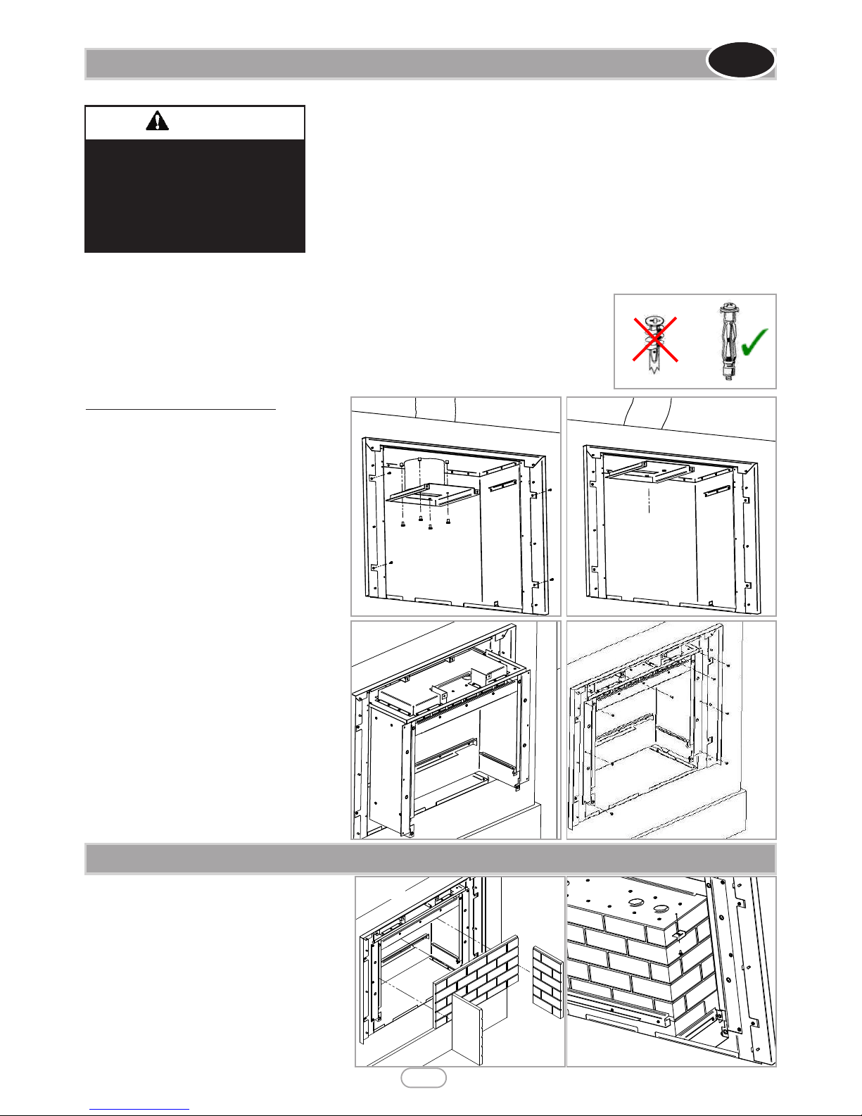
If there is no alternative than to rely on some plasterboard fixings then special cavity screw fixings or
hollow wall anchors will be required which are not supplied with this product. These should be constructed from metal and not plastic and of the design indicated in figure 7.
The wall where the appliance is
to be installed must be capable
of long-term support of the total
load of the appliance. Measures
should also be taken to ensure
sufficient strength to withstand
the force of earthquakes, vibration and other external forces.
WARNING
Figure 7
GB IE
Fixing the appliance - All Models
Offer the appliance into the opening to ensure a
good fit, once in the final position mark the positions shown in figure 8 on the wall. If a concealed
gas connection is to be made ensure the gas supply pipe is in its final position and can enter the
appliance in the correct position when the appliance is installed into the opening.
Drill the wall as appropriate for the type of wall
as previously described in this section, and insert
the chosen type of wall fixings. Insert the wall fixing screws into the top wall plugs.
Insert the lower fixing screws into the lower wall
plugs through the corresponding fixing holes in
the lower part. Locate the flue through the top of
the firebox and attach the bottom of the flue liner
to the flue adapter. Seal the two together using
self tapping screws and aluminium tape (not supplied).
Screw the flue adapter to the top of the external firebox, ensuring the flue is still attached in
the correct position.
Next, using the guides in the top of the left hand
and right hand of the external firebox, guide the
internal firebox into position. Once in position,
screw the 6 self tapper screws and 2 M4 screws
at the top to secure the two fireboxes together.
Figure 8
Figure 9
Figure 10
Figure 11
7.4 INSTALLING THE CERAMIC TILES
Carefully insert the rear brick panel into the rear of
the firebox, behind the bottom lip. Ensure the brick
effect is in the correct orientation,with the lip on the
top edge.
Install one side brick panel in the left hand side of the
firebox, behind the bottom return.
Install the right hand brick panel in the same manner
(the brick effect panels are not labelled). Ensure the
brick effect is in the correct orientation, with the lip
on the top edge, so the brick effect is continuous
around the firebox.
Next screw the “L” ceramic clamps into position in
both side of the firebox with the self tapping screws.
Figure 12 Figure 13

The spark gap (shown in figure 15) between the spark electrode and the thermocouple
should be 3.5 - 4.5mm to produce a good spark.
There should be no need to adjust this.
If under any circumstances the electric spark fails, the pilot may be lit manually by proceeding with the ignition sequence as previously described, and after sliding the control knob
through the spark position, the knob should be held fully to the right and the pilot lit with
a taper.
7.6 GAS CONNECTION
Important Note: Check the thermocouple nut connection into the rear of the valve is secure.
Temporarily fit the burner unit and ensure a suitable gas route can be achieved. Purge the gas supply thoroughly to remove air and
dirt/debris before connection. Disconnect the inlet restrictor elbow from the inlet pipe.
Connect the previously installed gas supply to inlet restrictor elbow. Place the burner unit into the firebox making sure that the rear of
the burner bracket fits into the rear of the firebox. Fit the two screws through the burner support brackets to secure the burner assembly into position. Re-fit the restrictor elbow to the inlet pipe of the appliance.
8
© 2017 Focal Point Fires plc.
7.5 INSTALLING THE BURNER
GB IE
Replace burner unit by screwing the two screws either side of the burner as shown in
figure 14.
Figure 14
8.2 INSTALLING THE CERAMICS
For installation of the fuel bed layout, refer to sections 7.0 and 7.1 of the user instructions.
Figure 15
Spark gap
8.1 SPARK GAP
8.0 TESTING AND COMMISSIONING
Turn on and test the gas supply up to the fire for any leaks, in accordance with current edition of BS6891.
When the appliance is first used, protective oils coating the burner may burn off. It is advisable to ventilate the room during this period
for at least one hour.
8.3 ASSEMBLING THE APPLIANCE
Re install the glass assembly, by screwing the screws in each of the corners of the glass
assembly.
Figure 16
 Loading...