

Ekofires 6010, 6020, EKO 6030 Install And User Manual
INSTALLATION & USER INSTRUCTIONS
All instructions must be handed to the user for safekeeping.
MODELS COVERED BY THESE INSTRUCTIONS
HIGH EFFICIENCY GAS STOVE
Please note : Except where otherwise stated, all rights, including copyright in the text, images and layout of this booklet is
owned by Focal Point Fires plc. You are not permitted to copy
or adapt any of the content without the prior written permission of Focal Point Fires plc.
1
Revision B- 11/14
GB IE
IN THE UK ALWAYS USE A GAS SAFE REGISTERED ENGINEER TO INSTALL, REPAIR OR SERVICE THIS APPLIANCE
MODEL SHOWN : 6020 FLUELESS STOVE
6010 & 6020 FLUELESS STOVE
© 2014 Focal Point Fires plc.
Christchurch, Dorset BH23 2BT
Tel: 01202 588 638
Fax: 01202 499 639
www.ekofires.co.uk
e-mail: sales@ekofires.co.uk
• This appliance is a high efficiency, flueless catalytic flame effect gas fire. It provides radiant and convected warmth both efficiently
and safely utilising the latest type of catalytic converter and burner technology.
• The appliance does not require a flue system of any type as the catalytic converter cleans the flue products to provide a complete combustion system, which is intrinsically safe. It is designed to operate on Natural Gas or LPG and is factory set for operation on the gas type, and at the pressure stated on the appliance data plate.
• The appliance incorporates a combustion monitoring system (Oxygen Depletion System). It must not be adjusted or put out
of operation. If replaced then manufacturer’s original parts must be used.
• This appliance must be installed by a GAS SAFE registered person to ensure that the size of the room in which the appliance
is to be installed is sufficient and the ventilation provision for that room is sufficient for the appliance. Details of how to determine the suitable room size is given in section 3.1 of these instructions and details of how to determine suitable ventilation are
given in section 4.1.
• In the event of gas leakage from the appliance, the gas supply must be turned off at the nearest isolating valve.
• The appliance must be installed in accordance with the following:
• Failure to comply with the above could lead to prosecution and deem the manufacturer’s warranty invalid.
• This appliance must be installed in accordance with the rules in force and used only in a sufficiently ventilated space. The appli-
ance is designed to fit various types of situations as described in sections 3.0 and 4.0. The appliance must be installed in a correctly sized room (see section 3.1), and the correct purpose provided ventilation must be provided (see section 4.1).
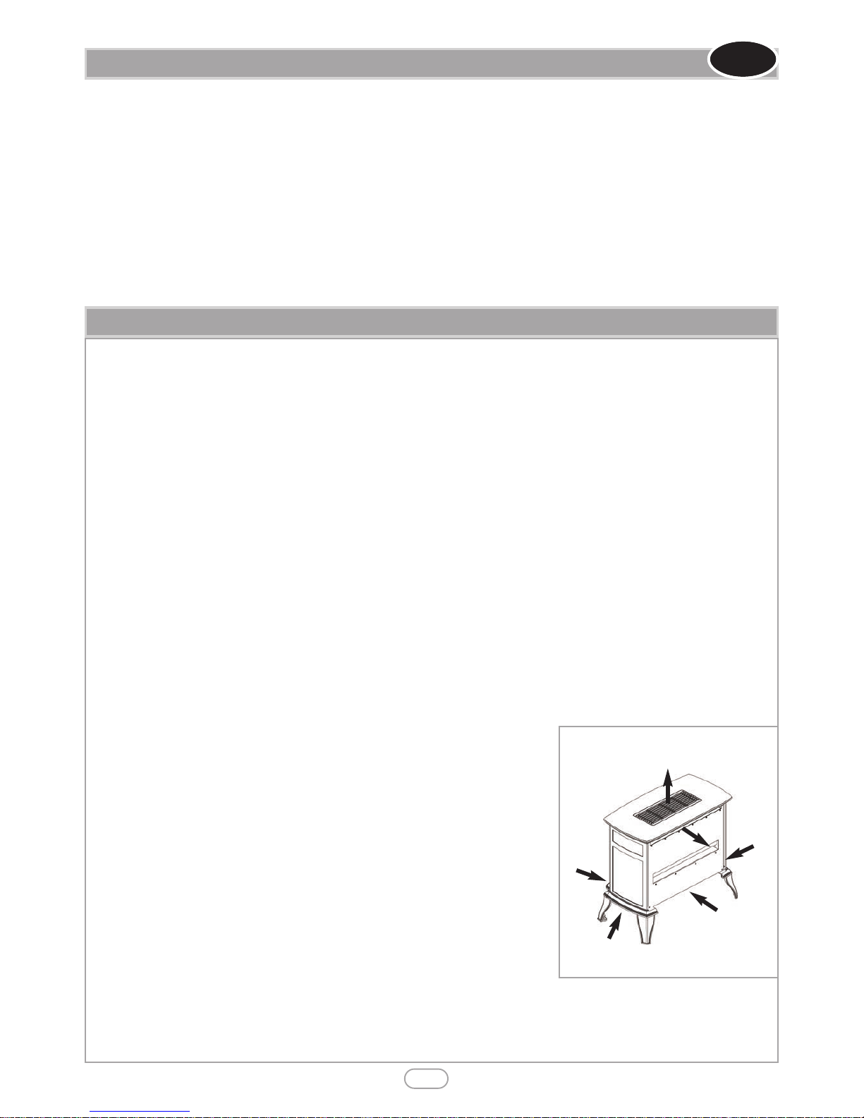
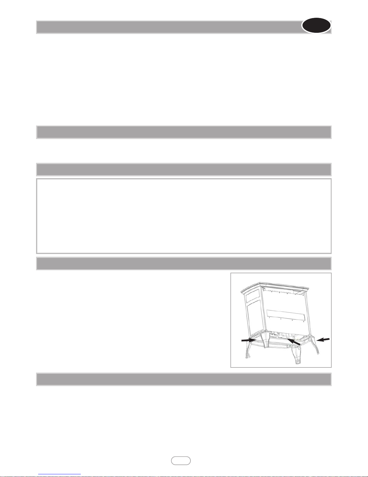
• On no account should the appliance inlet or outlet openings be blocked or obstructed in any way (see figure 1). Do not place
objects on top of the appliance.
• It should be noted that heaters create warm air currents. These currents move heat
to wall surfaces next to the heater. Installing the heater next to vinyl or cloth wall coverings or operating the heater where impurities in the air (such as tobacco smoke, candle smoke etc.) exist, may cause the walls to become discoloured.
• This appliance is intended as a secondary source of heat only and should not be used in a
room without some form of background heating present. If the appliance is used in a room as
the sole source of heat, then condensation may occur on colder surfaces within the room.
• On first light up of a new appliance, burning off of high temperature paint and lubricants may occur for the first few hours of operation. During this period some smoke
may be emitted from the outlet grille, this should be no cause for concern. Accordingly,
the room should be well ventilated with all windows and doors open during this period. During this period the appliance may cause smoke alarms to sound. If this happens,
reset the alarms, but do not remove the batteries.
• WARNING: Due to the nature of this product the area around the top of the appliance (i.e. the grille) gets very hot. Care should be taken when operating the appliance.
The manufacturer of this appliance considers all surfaces as working surfaces with the
exception of the control knob. The guard (glass front) is to prevent risk of fire or injury from burns and no part of it should
be permanently removed. It Does Not Give Full Protection For Young Children Or The Infirm. Where young children,
pets, the elderly or infirm are concerned, a suitable fireguard should be used.
• Consult ALL instructions before installation and use of this appliance. This appliance is free from any asbestos material.
Section Contents Page No.
1.0 Important Notes 2
2.0 Appliance Data 3
3.0 Installation Requirements 3
3.1 Room Sizing 3
4.0 Site Requirements 3
4.1 Ventilation 5
5.0 Unpacking the Appliance 5
5.1 Component Checklist 5
6.0 Gas Supply Routes 5
7.0 Fixing the Appliance 5
7.1 Removing/ Installing Castings 6
Section Contents Page No.
7.2 Installing the ceramics 6
8.0 Testing and Commissioning 7
8.1 Checking the Burner & Spark Gap 7
8.2 Operating the Appliance 8
8.3 Operating Pressure 8
9.0 Briefing the customer 8
10.0 Servicing 8
10.1 Servicing the Burner Unit 9
10.2 Pilot Assembly 9
10.3 Catalysts 9
10.4 Testing for Firebox Leakage 9
11.0 Troubleshooting Guide 10
1.0 IMPORTANT NOTES
I N S T A L L A T I O N I N S T R U C T I O N S
Figure 1
Outlet openings :
DO NOT BLOCK
Inlet openings :
DO NOT BLOCK
2
GB IE
• Manufacturers' Instructions.
• The Building Regulations issued by the Department for Communities and Local Government, the Building Standards (Scotland)
(Consolidation) Regulations issued by the Scottish Development Department.
• Relevant British standards insofar as the relevant areas are not covered by these instructions.
• For Republic of Ireland, reference should be made to the current edition of IS813 (the relevant standards governing installation).
© 2014 Focal Point Fires plc.
2.0 APPLIANCE DATA
3
Destination Country
Gas Type Cat
Inlet/Operating
Pressure (±2.0 mbar)
Max Energy Input (kW) Min Energy Input (kW)
G20 G25 G30 G31 Gross Net Gross Net
GB - IE
Natural
I
2H
20 -
- - 3.1 2.8 1.5 1.35
Propane
I
3P I3+
--
- 37 3.1 2.8 1.5 1.35
GB IE
Please see Data Badge affixed to appliance for current data.
This appliance is for use only with the gas type, and at the pressure stated on the appliance Data Badge.
If the appliance is to be sited near a disused or unserviceable fireplace served by a natural draught flue then the old flue must be sealed
off. It will be necessary to ventilate the old flue to prevent condensation and dampness forming, however any air vent used to ventilate
the old flue must not be sited within 1000mm of this appliance. If the flue can be ventilated to the outside of the building then this is
usually the best solution. If in doubt then advice should be sought from a local building control officer. The appliance is designed to be
floor mounted. If the appliance is to be mounted in front of a newly fabricated area of wall that also serves the purpose of sealing off
the old flue then it is very important that there are no holes, gaps or otherwise in this wall that will allow draughts from the old flue to
enter the room, especially directly behind the appliance. Such draughts could affect the performance of the ODS system and result in
nuisance cutting out, for example. If the gas supply pipe is to enter the appliance from the rear, i.e. emerge from the wall behind the appliance, then any hole in the wall from which the pipe emerges must be tightly sealed. Propane/LPG models must not be installed in cellars,
basements or any room which is completely below ground level.
The room size MUST be a minimum of 35m
3
(e.g. 3.8m x 3.8m x 2.425m or 12'5" x 12'5" x 8').
This is to allow adequate circulation of air and ensure the correct operation of the fire. This volume may include adjacent spaces but
these spaces must not be separated by a door. Note : To calculate a room size in cubic metres (m
3
) divide the room volume in cubic
feet (ft
3
) by 35.3.
This appliance may be installed in any room in the home except bathrooms. In accordance with BS5871 part 4, installation in bedrooms
is permitted. If the appliance is to be installed in a bedroom then an electronic carbon monoxide detector complying with the current
edition of BSEN 50291 must be installed in the same room as the appliance. For maximum safety it is recommended that such device is
continuously (mains) powered and arranged in such a way that the gas supply
to the appliance is isolated in the event of an alarm. The selection and installation of such device shall be in accordance with the current edition of BSEN
50292, and the user must be briefed regarding the use and maintenance of
such a device.
The appliance is designed to be versatile, and as such will operate correctly
when exposed to normal gentle draughts experienced within the home. It is
not recommended, however that the appliance be installed in areas where it
is likely to be directly exposed to persistent strong draughts, that may be generated by outside doors, windows, air vents, air conditioning units, extractor
fans, ceiling fans etc. See section 4.1 for more information on ventilation.
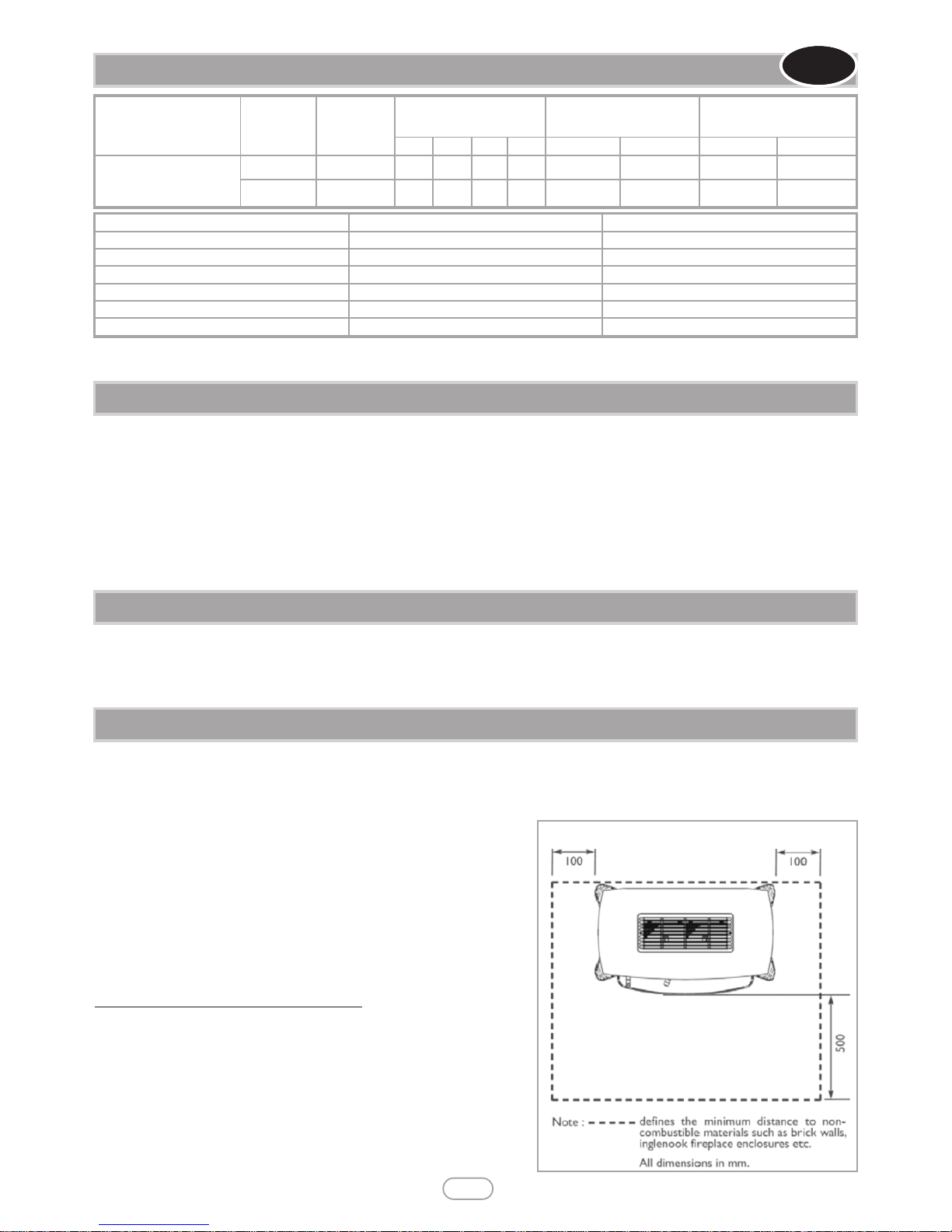
Clearances to non-combustible materials
Non combustible surfaces are defined as brick, metal, natural stone, concrete
etc. and also a number of man-made materials impervious to flame. If in doubt
refer to the material manufacturer for further information before proceeding
with installation.
Clearances to the sides of the appliance are 100mm (4”). Clearance to the
front of the appliance is 500mm (20”).
The back of the appliance may be installed directly in front of a non-combustible wall, providing the area behind the appliance is flat and does not interfere with the various vent holes in the back panel of the appliance.
3.1 ROOM SIZING
4.0 SITE REQUIREMENTS
Specifications NG Models LPG Models
Main burner injector Stereo size 1.30 Stereo size 83
Oxypilot SIT 9110/ Copreci 21100 2F/CHMU13125A TBC
Gas Control Teddington TESA 3173/011 Teddington TESA 3173/011
Gas Inlet 8mm restrictor elbow 8mm restrictor elbow
Ignition Battery Spark Battery Spark
Spark Gap 3.5 - 4.5mm 3.5 - 4.5mm
3.0 INSTALLATION REQUIREMENTS
Figure 2
© 2014 Focal Point Fires plc.
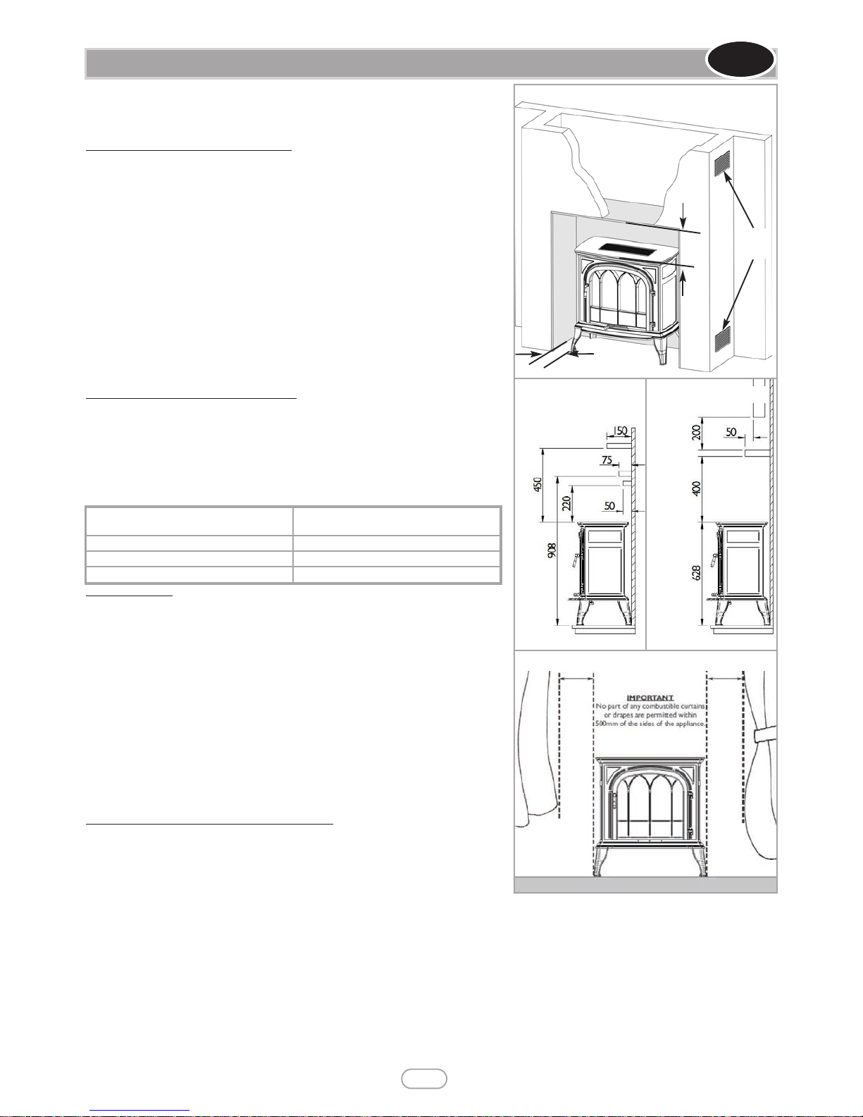
A non-combustible shelf of any depth may be positioned above the appliance provided it is no closer than 220mm (8.66”) from the top of the appliance glass panel
and the wall above the appliance is non combustible. The appliance can be mounted directly onto all types of combustible floors and hearths.
Inglenooks & false chimney breasts
Where fitting in an inglenook or false chimney breast, the top, back and sides of
the inglenook wall must be of a non combustible material such as calcium silicate,
brick, or stone. Sizes and clearances must be in accordance with figure 2. If a void
is created in a false chimney breast above the appliance it should be vented at
high and low levels to allow air circulation (see figure 3). These vents should communicate with each other via the space inside of the false chimney breast in
order to prevent heat build-up within the void and maximise the heat released
into the room. Inside the inglenook, the minimum clearance from the top of the
appliance is 220mm. Refer to figure 2 for clearance to the back, sides and front of
the appliance.
Where an inglenook type installation is created below a disused flue then the flue
should be properly de-commissioned and sealed at the base using non-combustible materials. The old flue should be ventilated to prevent condensation and
possible damage to the fabric of the building. This ventilation cannot be used as
purpose provided ventilation for the appliance and separate provision must be
made for this (refer to section 4.1 for information on ventilation).
Clearance to combustible materials
For other types of installations, it may be necessary to install the appliance in proximity to combustible materials. Combustible materials are generally defined as
wood, fabrics, or other materials likely to combust if exposed to flame. Generally
any material, which is likely to discolour, melt or misshape when exposed to moderate heat, should be considered as a combustible material or surface. If a combustible shelf or wooden fire surround are to be sited in proximity to the stove the
following clearances (see figure 4) must be adhered to;
TV installation
Note; TV manufacturer’s instructions must be consulted and take precedence
insofar as positioning of heating appliances are concerned. If the stove is to be
installed underneath a wall-mounted TV, then this can be achieved by installing a
shelf above the appliance to protect the TV from the heat produced by the stove.
The shelf must be constructed from a non-combustible material positioned
400mm from the top of the appliance. There must then be a clearance of 200mm
from the top of the shelf to the bottom of the TV. The depth of the shelf depends
on the depth (or protrusion from the wall) of the TV but must extend at least
50mm outward from the front of the TV. See figure 5. If a minimum distance of
50mm to the TV from the shelf front cannot be achieved it is acceptable to position the stove forward from the wall and use a deeper shelf. If this the case then
the stove must be installed so as to prevent movement back to the wall. The noncombustible shelf must not project further forward than the back edge of the
outlet grille on the top of the stove. In all cases the shelf must extend at least
50mm forwards from the TV.
Clearance to other combustible materials
Clearance to the sides of the appliance are 100mm (4”) but curtains, drapes and
other fabrics are not permitted within a distance of 500mm (20”) of the appliance
side (see figure 6). No such materials are permitted directly above the appliance
regardless of distance.The minimum clearance to the celling above the appliance is
800mm (31.5”) measured from the top of the appliance.Combustible materials
should not be positioned directly in front of the appliance within a distance of 1000mm.
It should be established that any mirrors or picture frames etc. to be positioned on the wall above the appliance are able to withstand
prolonged exposure to moderate heat, before they are fitted above the appliance or the appliance is installed underneath them.
The back of the appliance may be installed directly in front of a combustible wall, providing it is flat and does not interfere with the various vent holes in the back panel of the appliance. The wall must be structurally sound and be constructed from a material capable of
withstanding moderate heat. Brick, concrete, finished plaster, most types of conventional wall paper and dry-lined plasterboard are usually examples of suitable materials, however as there are many methods of wall construction and many variations in the composition of
construction materials, in some circumstances, cracking may occur to plasterwork. Materials such as flock, blown vinyl and embossed
paper which are sensitive to even small amounts of heat should be avoided as scorching and or discolouration may occur over time.
Avoid siting the appliance near joins or joints in plasterboard as exposure to moderate heat may cause cracking along the joint line. The
appliance weighs 32kgs and it is important that the floor can support this weight. Take care that loose rugs are kept clear of the appliance as these can move against the appliance and become damaged.
4.0 SITE REQUIREMENTS (CONTINUED)
GB IE
4
TV
All dimensions
in mm
All dimensions
in mm
Figure 4
Figure 5
Figure 3
All dimensions
in mm
220
Figure 6
All dimensions in mm
500
500
High and
low level
vents
100
© 2014 Focal Point Fires plc.
Maximum depth of shelf
Minimum distance from the top of the
appliance to the underside of the shelf
50mm 220mm
75mm 280mm
150mm 450mm
All installation pipework must be in accordance with the current edition of National regulations/codes and the rules in force.
In order to avoid unnecessary pressure drops, use of small diameter pipe should be kept
to a minimum, for example, we recommend no more than 1.5 metres of 8mm pipe. If a
concealed gas connection is to be made, the supply pipe should always be sleeved
through walls and floors using the shortest possible route. For concealed supply pipe
routing, pipes must (where possible) be vertical and providing there is sufficient wall
thickness available, they should be placed in pipe chases. Horizontal pipe runs should be
avoided. Prior to chasing a solid wall, an inspection should be made to note the proximity of any cables/sockets outlets which may be buried. Pipes must be secured using
suitable clips and protected against corrosion. Ideally factory finished protected
pipework and fittings should be used. Joints should be kept to a minimum and compression fittings must not be used. The pipework installation must be tested for tightness
before any protection is applied and/or the pipework and fittings are buried.
Position the stove in the proposed final location in accordance with sections 3.0, 3.1, 4.0, 4.1 and 6.0. If the hearth or floor surface is
uneven, there are two adjustment feet that can be fitted behind the front two cast legs. Unscrew in a anti clockwise orientation to
extend the feet and clockwise to contract the front legs. The horizontal alignment of the stove may be checked with a spirit level.
Ensure that the stove sits on the adjustment feet not the legs as they prevent the fire from sliding on smooth surfaces.
6.0 GAS SUPPLY ROUTES
5
7.0 FIXING THE APPLIANCE
Figure 7
5.1 COMPONENT CHECKLIST
QUANTITY DESCRIPTION
1 Stove assembly
1 Set of manufacturers instructions
1 Control handle
1 Decorative handle
1 M6 x 15mm
1 Control handle position marking sticker
1 Log set (1 x Front & 2 x Rear)
2
Levelling feet
1 Tiled ceramic set (2 x side panels & 1 x back)
2 No.8 x 5/16” screws
2 “L” brackets
5.0 UNPACKING THE APPLIANCE
Remove the outer packaging, remove any instructions. Read ALL these instructions before continuing to unpack or install this appliance.
Lift off the remaining packaging components and remove the contents of the box. Check that the components supplied correlate with
the component checklist. Please dispose of all the packaging materials at your local recycling centre
.
4.1 VENTILATION
GB IE
If the room in which the appliance is installed is naturally ventilated, a minimum of 100 cm²purpose provided ventilation MUST be provided for this appliance. This may be achieved either with one vent 100 cm
2
at a high or low position in the room, or split ventilation i.e.
50 cm
2
to be installed at high level and 50 cm2to be installed at low level within the room. An openable window or equivalent is also
required. To reduce the possibility of draughts, road noise or insects entering the room via the air vent, we recommend an air vent of
the type that feature internal baffles. Ventilation fitted under, or within immediate vicinity of the appliance must not be used as it may
adversely affect performance of the ODS system. The appliance shall not be installed within one metre of any existing air vent, and any
new air vent shall not be installed within one metre of the appliance.
If the room in which the appliance is to be installed is served by heat recovery ventilation (HRV) or energy recovery ventilation (ERV)
then no purpose provided ventilation is required but a room air change rate of at least one air change per hour is required for this appliance. The appliance MUST be interlocked with the ventilation system such that it is only possible to operate the appliance if the ventilation system is in operation. In all cases, the requirements of any other gas, oil or solid fuel appliances operating in the same room or
space must be taken into consideration when assessing ventilation. All ventilation must communicate directly with outside air and must
not pass through rooms or voids unless ducted. Any ventilation fitted must comply (where applicable) with BS 5871 part 4 and BS 5440
part 2. For Republic of Ireland refer to the current edition of IS813 and any relevant rules in force.
© 2014 Focal Point Fires plc.
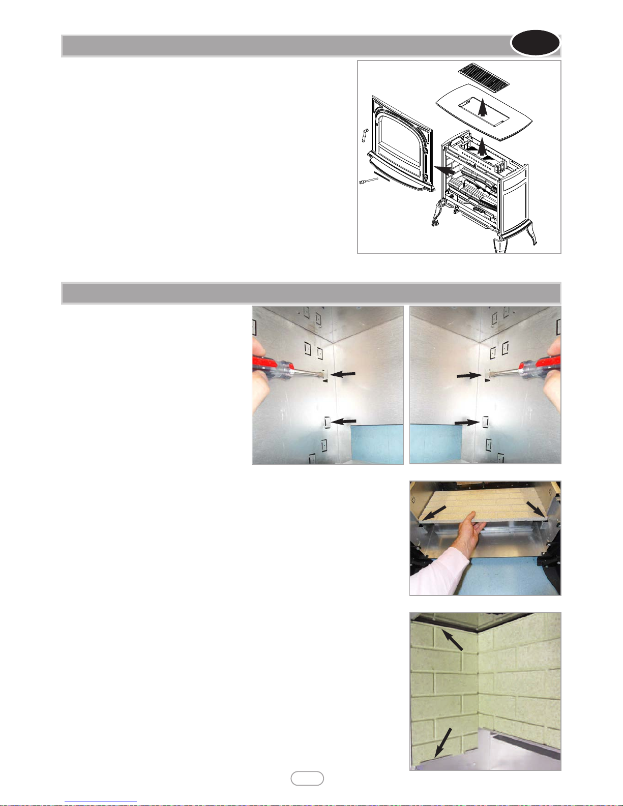
7.2 INSTALLING THE CERAMICS
6
Ensure that the fire is off and cool before attempting to remove or
assemble castings.
The stove is supplied with the castings fitted. To fit the fuel bed it is necessary to
partially dis-assemble the stove as follows;
1) Remove the top grille by the two screws in the top of the appliance,push the
rear of the grille down so the front end of the grille lifts up. DO NOT LEVER
OFF WITH A SCREWDRIVER.
2) Remove the top casting by unscrewing the four screws holding it in place.
3) Unscrew the cross head screw holding the front casting down at the top. The
front casting is now free to be removed.
4) Remove the glass door by unscrewing the four retaining screws in each corner.
5) Remove the burner assembly which is fitted with one screw either side.
6) Fit the ceramic components as detailed in section 7.2.
7) Re-fit the burner and the glass door after cleaning or inspection, ensuring a
good seal.
8) Attach the decorative handle to the front casting using the M6 x 15mm screw
supplied.
9) To re-assemble the castings read instructions in reverse order.
10) Attach the control handle to the burner assembly through the opening in the front panel.
Figure 8
7.1 REMOVING/INSTALLING THE CASTINGS
GB IE
© 2014 Focal Point Fires plc.
Use a flat blade screw driver to carefully lever
the two rear return tabs out to 90° on both left
and right hand sides of the firebox as shown.
These tabs can also be identified as they do not
feature a dot on, like the other tabs.
Lay the firebox onto it’s back on a soft surface so you are able to slot the rear brick panel
through the bottom of the firebox as shown, in front of the returned tabs but behind the
bottom lip. Ensure the brick effect is in the correct orientation, with the lip on the top
edge.
Install one side brick panel in the left hand side of the firebox, behind the bottom return.
Install the right hand brick panel in the same manner (the brick effect panels are not
labelled). Ensure the brick effect is in the correct orientation, with the lip on the top edge,
so the brick effect is continuous around the firebox.
Figure 10
Figure 9
Figure 11
Figure 12
 Loading...