

EKM Omnimeter I Installation Instructions Manual
EKM Metering Inc. – www.ekmmetering.com – info@ekmmetering.com – (831)425-7371
• Nominal Voltage Ranges:
120V to 480V, 2-wire, Single-phase, One Line & Neutral
120V to 480V, 3-wire, Single-phase, 2 Lines & Neutral
120V to 415V, 3-wire, 3-phase, 3 Lines, No Neutral
120V to 480V, 4-wire, 3-phase, 3 Lines and Neutral
• Range of allowable environmental conditions: Pollution Degree 2,
Measurement Category III, Altitude rating 2000 meters max. Maximum
Temperature Range: -30 Deg. C to 70 Deg. C. Tamper Detection Class 1.
• The equipment is protected throughout by
double insulation as indicated by this symbol:
• Accuracy Class 0.5
• Rated Frequency: 50Hz/60Hz
• Red LED on the meter face ashes 800 times/kWh. 1 ash = 1.25Wh.
• Received California Type Approval for revenue grade metering
Safety Precautions:
• Meter should be installed by a qualied electrician.
• Turn off all power supplying the equipment before preforming any
wiring. Use a properly rated volt meter to conrm power is off.
• Use of this device inconsistent with this manual can cause permanent
damage to the unit and/or serious harm to the operator.
Tools/Materials List:
• Volt meter
• Small standard screwdriver
• Wire stripper
• DIN-Rail
•16-22 AWG stranded copper wire
• Inline fuse holder with maximum 1Amp fuse
• Use a Type 4 Enclosure (with appropriate conduit and ttings) if meter
will be installed outdoors
Installation Instructions
For All Systems:
1. Disconnect or switch power off before attempting to install, connect,
disconnect or service the meter or the external current transformers
(CTs). ALL POWER MUST BE DISCONNECTED!
2. Mount the meter using 35mm DIN Rail in a protected indoor location.
If installing outdoors, a UL Listed Type 4 Enclosure is required.
3. IMPORTANT: Distinguish and then identify the Neutral and the Line(s)
(‘hot’ wire(s), usually black or red). Label the Neutral and then,
depending on your electrical system, assign labels as described below.
4. Tightening torque of terminals:
All terminals: 4.4 in-lb. (0.5 Nm)
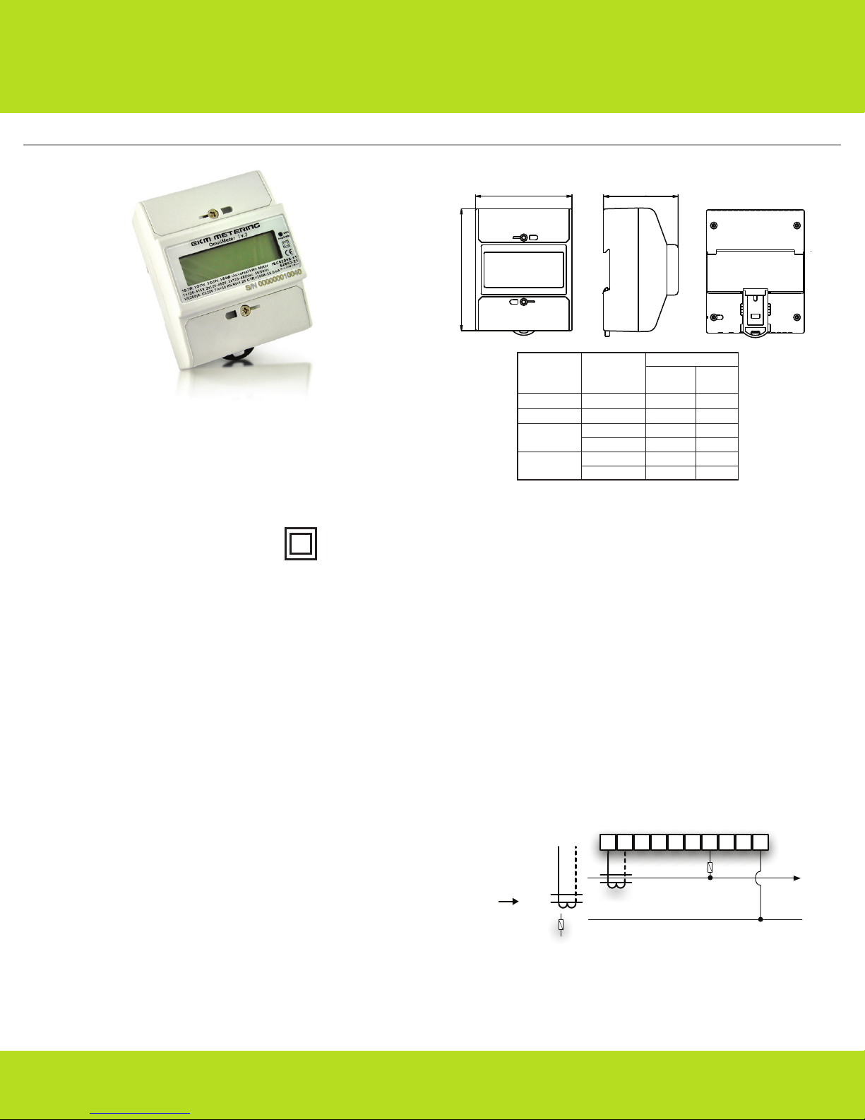
120V, 2-Wire, Single Phase:
1. Label Line 1 as L1.
2. Fit CT1 around L1. Make sure the arrow is facing towards the load (in
the direction of ow). (Fig 2)
3. Black CT wire connects to Port 1 on the Omnimeter. White CT wire
connects to Port 2. (Fig 2)
4. With split core CTs, close the CT around the wire to be measured and
press rmly until you feel and hear it click to indicate full closure. The
buttons should be fully out. Use a zip tieto ensure the CTs remain
securely closed.
5. To power the meter and get a voltage reference: Use a maximum 1.0
Amp inline fuse on L1. Connect one fuse holder pigtail to the breaker,
lug or an appropriate line-tap device, and connect the other pigtail to
16-22 AWG UL rated stranded copper wire for connection to the meter.
6. L1 connects to Port 7 on the Omnimeter, Neutral to Port 10. (Fig 2)
7. Once the meter is properly mounted to the DIN Rail or enclosure and
all wiring is completed, with terminal block covers installed, power can
be turned back on.
8. Meter will then begin cycling through meter values. For details go to:
http://documents.ekmmetering.com/EKM_Metering_LCD_Display_Value_Reading.pdf
9. A video of proper install of a 120V system can be found here:
http://www.youtube.com/watch?v=ky9sgr1LTMk
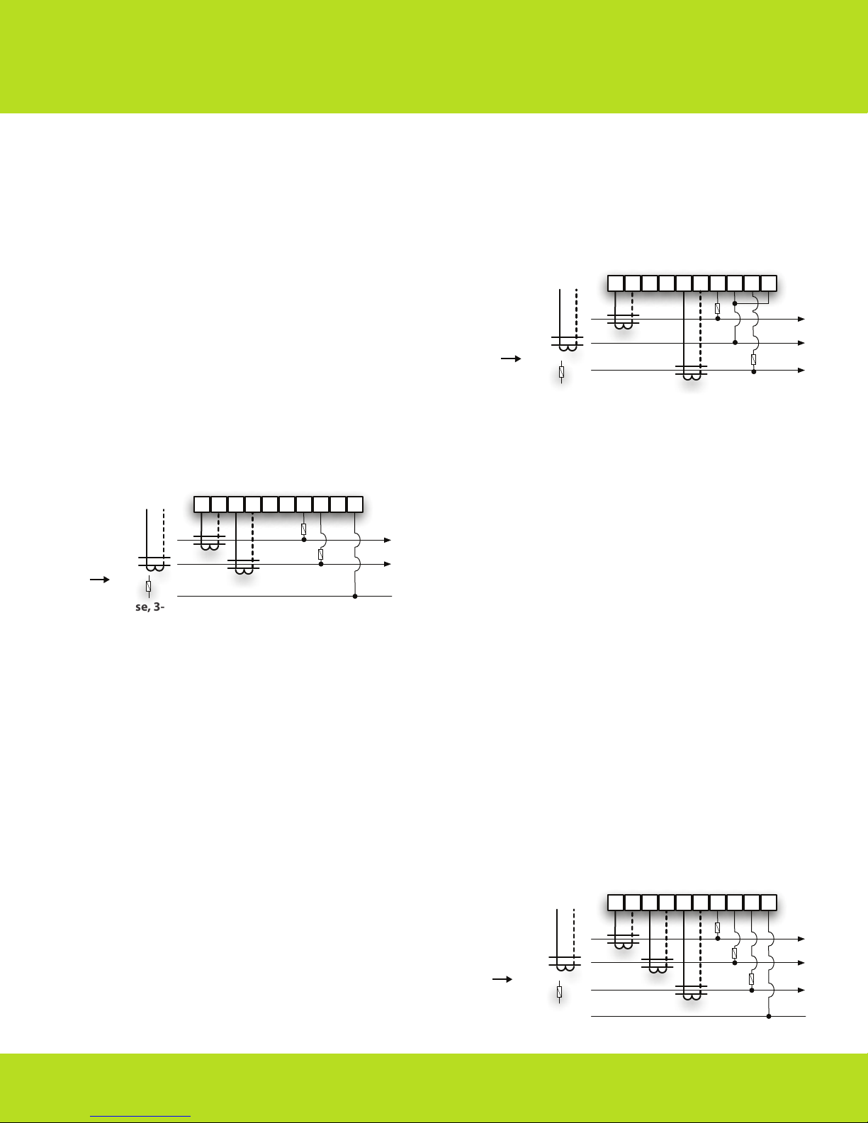
120/240V, 120/208V, Single Phase, 3-Wire:
1. Label L1 and L2. (Arbitrarily assign labels.)
2. You will be using 2 CTs for this install. Label them CT1 and CT2.
3. Fit CT1 around L1. Make sure the arrow is facing towards the load (in
the direction of ow).
4. Fit CT2 around L2.
(Fig 1)
(Fig 2)
EKM-Omnimeter I v.3 Spec Sheet
1 2 3 4 5 6 7 8 9 10
L1
L2/N
CT1
1 1
1
78
100
.
66.5
Load
current
Basic error %
Class 0.5
Class 1
0.05
I
b
1.0
1.0
1.0
+
–
0.5
+
–
1.0
+
–
1.0
+
–
0.5
+
–
0.5
+
–
1.5
+
–
1.0
+
–
1.5
+
–
1.5
+
–
1.0
+
–
1.0
+
–
0.5(L)
0.8(C)
0.5(L)
0.8(C)
0.1
Ib~Imax
0.1Ib
0.2
Ib~Imax
Power
factor
COSθ
120V, 240V
Single-Phase
2-Wire
Load
Blk Wht
Fuse
EKM Metering Inc. – www.ekmmetering.com – info@ekmmetering.com – (831)425-7371
Black wire from CT1 connects to Port 1 on the Omnimeter. White wire
from CT1 connects to Port 2. (Fig3)
Black wire from CT2 connects to Port 3. White wire from CT2 connects
to Port 4. (Fig 3)
With split core CTs, close the CT around the wire to be measured and
press rmly until you feel and hear it click to indicate full closure. The
buttons should be fully out. Use a zip tieto ensure the CTs remain
securely closed.
To power the meter and get a voltage reference: Use a maximum 1
Amp inline fuse on L1 and L2. Connect one fuse holder pigtail to the
breaker, lug, or an appropriate line-tap device. Connect the other
pigtail to 16-22 AWG UL rated stranded copper wire.
Tap into L1 with a small stranded copper wire. This L1 tap connects to
Port 7 on the Omnimeter with a 1A fuse inline. (Fig 3)
Tap into L2 with a small stranded copper wire. This L2 tap connects to
Port 8 on the Omnimeter with a 1A fuse inline. (Fig 3)
Neutral connects to Port 10.
Once the meter is properly mounted to the DIN Rail or enclosure and
all wiring is completed, with terminal block covers installed, power
can be turned back on.
Meter will then begin cycling through meter values. For details go to:
http://documents.ekmmetering.com/EKM_Metering_LCD_Display_Value_Reading.pdf
A video of a proper install of a 120V/240V system can be found here:
http://www.youtube.com/watch?v=ky9sgr1LTMk
Label L1, L2 and L3. (Arbitrarily assign labels.)
You will be using 2 CTs for this install. Label them CT1 and CT3.
Fit CT1 around L1. Make sure the arrow is facing towards the load (in
the direction of ow).
Fit CT3 around L3.
Black wire from CT1 connects to Port 1 on the Omnimeter. White wire
from CT1 connects to Port 2. (Fig 4)
Black wire from CT3 connects to Port 5 on the Omnimeter. White wire
from CT3 connects to Port 6. (Fig 4)
With split core CTs, close the CT around the wire to be measured and
press rmly until you feel and hear it click to indicate full closure. The
buttons should be fully out. Use a zip tieto ensure the CTs remain
securely closed.
To protect the meter, use a maximum 1.0 Amp inline fuse on each line.
To power the meter and get a voltage reference:
Tap into L1. Connect one fuse holder pigtail to the breaker, lug or an
appropriate line-tap device, and connect the other pigtail to16-22
AWG UL rated stranded copper wire for connection to the meter. This
L1 tap connects to Port 7 on the Omnimeter. Tap into L2 and L3 and
repeat the connection process. L2 tap connects to Port 8. Be sure to
add a jumper to Port 10. (Fig 4) L3 tap connects to Port 9.
Once the meter is properly mounted to the DIN Rail or enclosure and
all wiring is completed, with terminal block covers installed, power
can be turned back on.
Meter will then begin cycling through meter values. For details, go to:
http://documents.ekmmetering.com/EKM_Metering_LCD_Display_Value_Reading.pdf
A video of a proper 120V-208V, 3-Wire, 3-Phase system can be found
here: http://www.youtube.com/watch?NR=1&v=upNgFNV6EDM
Label L1, L2 and L3. (Arbitrarily assign labels.)
You will be using 3 CTs for this install. Label them CT1, CT2 and CT3.
Fit CT1 around L1. Make sure the arrow is facing towards the load (in
the direction of ow).
Fit CT2 around L2.
Fit CT3 around L3.
Black wire from CT1 connects to Port 1 on the Omnimeter. White wire
from CT1 connects to Port 2. (Fig 5)
Black wire from CT2 connects to Port 3 on the Omnimeter. White wire
from CT2 connects to Port 4. (Fig 5)
Black wire from CT3 connects to Port 5 on the Omnimeter. White wire
from CT3 connects to Port 6. (Fig 5)
With split core CTs, close the CT around the wire to be measured and
press rmly until you feel and hear it click to indicate full closure. The
buttons should be fully out. Use a zip tieto ensure the CTs remain
securely closed.
Use a max 1.0 Amp inline fuse on each line to protect the meter.
To power the meter and get a voltage reference: Tap into L1 at the
breaker panel. Connect one fuse holder pigtail to the breaker, lug or an
appropriate line-tap device, and connect the other pigtail to 16-22
AWG UL rated stranded copper wire for connection to the meter. L1
connects to Port 7. Tap into L2 and L3 and repeat the connection
process. L2 connects to Port 8. L3 connects to Port 9. Neutral
connects to Port 10. (Fig 5)
Once the meter is properly mounted to the DIN Rail or enclosure and
all wiring is completed, with terminal block covers installed, power can
be turned back on.
Meter will then begin cycling through meter values. For details, go to:
http://documents.ekmmetering.com/EKM_Metering_LCD_Display_Value_Reading.pdf
A video of proper install of a 120V-208V, 3-Phase, 4-Wire system can be
found here: http://www.youtube.com/watch?v=DeKiZddR0K8
5.
6.
7.
8.
9.
10.
11.
12.
13.
14.
1.
2.
3.
4.
5.
6.
7.
8.
9.
10.
11.
12.
1.
2.
3.
4.
5.
6.
7.
8.
9.
10.
11.
12.
13.
14.
120V-480V, 3-Phase, 4-Wire:
120V-415V, 3-Phase, 3-Wire:
(Fig 3)
(Fig 4)
(Fig 5)
1 2 3 4 5 6 7 8 9 10
L1
L2
L3
N
CT1
CT2
CT3
1 2 3 4 5 6 7 8 9 10
Line1
Line2
Line3
CT1
CT3
1 2 3 4 5 6 7 8 9 10
L1
L2
N
CT1
CT2
Blk Wht
Fuse
120~480V
Line to Line
3-Phase
4-Wire
Load
120~415V
Line to Line
3-Phase
3-Wire
Load
120/240V
120/208V
Single-Phase
3-Wire
Load
Blk Wht
Fuse
Blk Wht
Fuse
Note: 3-phase, 3-wire, 480v electrical systems cannot be metered with
this meter model. For 3-phase, 480v electrical systems, the Omnimeter
must have a true neutral in order to meter accurately and avoid being
damaged by high voltages. In cases where there is no neutral on the
system being metered, it may be possible to run a neutral from the
transformer or electrical panel, to the Omnimeter. Again, this meter
must have a true neutral in order to meter 3-phase, 480 volt, electrical
systems. This would make it a 3-phase 4-wire system and would also
require a 3rd current transformer.
 Loading...