

EKM 25IDS-N Installation Instructions Manual
EKM-25IDS-N v.2 Spec Sheet
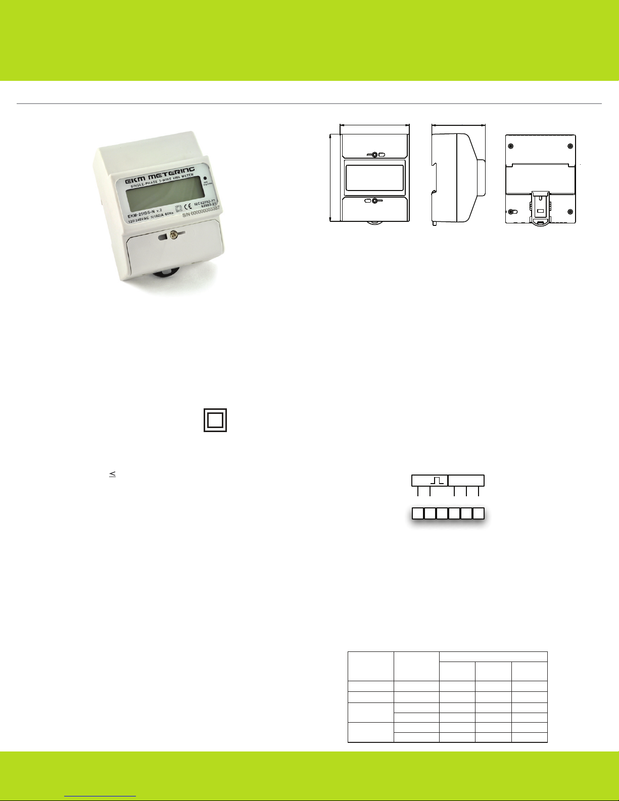
Techical Specications:
• 120/240V Single Phase, pass-through kWh meter
• Rated Voltage: 120/240 volts
• Rated current: 5(100)A
• Works with wires up to 3/8” in diameter
• Pulse output impulse constant: 800imp/kWh
• Range of allowable environmental conditions: Pollution Degree 2,
Measurement Category III, Altitude rating 2000 meters max. Maximim
Temperature Range: -30 Deg. C to 70 Deg. C.
• The equipment is protected throughout by
double insulation as indicated by this symbol:
• Accuracy Class: 1 (Fig 3)
• Rated Frequency: 50Hz/60Hz
• Creep: Logical design of anti-creep
• Start current: 0.4% Ib. (1.0)
• Power consumption: 1W (when 220V, 20A)
• Tamper Detection Class 1.
• Weight: 0.32kg
• Outside dimensions: 78x100x65mm (Fig 1)
Safety Precautions:
• Meter should be installed by a qualied electrician.
• Turn off all power supplying the equipment before preforming any
intallation or service. Use a volt meter to conrm power is off.
• Use of this device inconsistent with this manual can cause permanent
damage to the unit and/or serious harm to the installer or operator.
Tools/Materials List:
• Volt meter
• Small standard screwdriver
• DIN-Rail
• UL Listed Type 4 Enclosure (with appropriately rated conduit and
ttings) is required if meter will be installed outdoors
Functions:
• Long-term active electricity measuring without adjustment.
• Meets IEC 62053-21 and IEC 62052-11 standards (static AC active meter)
• With RS485 communication, index in accordance with IEC 62056-21(A
mode), which focuses on convenient intelligent energy management.
78
1
1 1
100
65
.
(Fig 1)
Installation Instructions:
1. Use a volt meter to conrm that you have 240 volts between L1 and L2.
This meter will not function correctly unless this is the case. For 120V
systems, use our any of the EKM-Omnimeter meter models.
2. Disconnect or switch power off before attempting to install, connect,
disconnect, or service the meter. ALL POWER MUST BE TURNED OFF!
3. IMPORTANT: Distinguish and then identify the 2 hot Lines and the
neutral line. Label all 3: L1, L2, N.
4. Once the power has been turned off, pass line 1 and line 2 through the
two holes in the meter. (for a retrot installation this may rst require
diconnecting the ends of L1 and L2 from a breaker or junction box)
5. Once the wires are through the meter, the ends should be reconnected
in their orignal positions. On the meter, tighten down the tap screws for
each line that passes through the meter. The tap screw will give the
meter its voltage reference as well as power the meter once the power
is turned back on.
6. Mount the meter using 35mm DIN Rail in a protected indoor location.
If installing outdoors, a UL Listed Type 4 Enclosure is required.
7. Once the above steps are completed, and you are ready, you can turn
the power back on and begin to read your meter.
SO RS485
_
+
123 4 5 6
RS-485 and Pulse Output(Fig 2):
• Terminal 4 (A) connects to RS-485+ or T+ on the RS-485 network.
Terminal 6 (B) connects to RS-485- or T-. Terminal 5 (G) is used for
the RS-485 network (signal) ground if needed. Observe proper RS-485
network topology. Twisted pair wiring is recommended. Shielded
twisted pair may be benicial in electrically noisy environments or for
very long runs. RS-485 supports up to 256 devices on up to 4000 feet
wire. Terminating resistors may be benecial.
• Terminals 1 and 2 are for pulse output. Pulse rate: 800 Impulse/kWh.
Polarity sensitive. Maximum 27VDC, 27mA.
Load
current
0.05
Ib~Imax
0.1
0.1Ib
0.2
Ib~Imax
I
Power
factor
COSθ
b
1.0
1.0
0.5(L)
0.8(C)
0.5(L)
0.8(C)
Class 0.5
A
+
1.0
–
+
0.5
–
+
1.0
–
+
1.0
–
+
0.5
–
+
0.5
–
B
G
Basic error %
Class 1
+
–
+
–
+
–
+
–
+
–
+
–
(Fig 2)
1.5
1.0
1.5
1.5
1.0
1.0
Class 2
+
2.5
–
+
2.0
–
+
2.5
–
---
+
2.0
–
---
(Fig 3)
EKM Metering Inc. – www.ekmmetering.com – info@ekmmetering.com – (831)425-7371

Working Principle:
When the meter is working, the energy consumed by the user is transformed into voltage and current signals, which are sampled by sample circuits. A
pulse signal is then produced by a specialized IC. The Pulse signal is directly proportional to power consumption. The MCU records and stores the
corresponding energy use. The LCD screen displays the energy use. Recorded information and data can be transferred using the RS485 interface.
Data:
The LCD display shows seven pieces of data: total electricity consumed(kWh), reverse kWh, voltage, current, total power, L1 COSθ, and L2 COSθ(power
factor). Every ve seconds the LCD screen will display a new piece of data. The meter also provides max demand(kW) data and the demand period can
be set to one of three intervals: 15minutes, 30 minutes, or 60 minutes. The max demand can be reset to zero in software over RS485. The meter has four
time-of-use tariffs(T1, T2, T3, T4) to calculate the power during different time periods, and it can set up to four time periods per day, and specify the
number of the tarrif for that period(from T1 to T4). The meter time can be set using the RS485 interface. By design the kWh cannot be reset. The meter
will go at least 10 years without power and still keep its kWh readings. In other words, the memory will not be erased if there is no power.
Transport and Handling:
The meter should be handled with care, as there are precision components inside that could break and/or cause faulty readings should the meter
become damaged. The process of transportation, handling, and installation should be done according to the transportation and storage rule of
GB/T15464-1995. Keep the meter in the original packaging when stored. The storage temperature range should be 0–40ºC. The relative humidity
should be 85%. There should be no toxic chemicals present and no corrosive substances or gases in the air. The meters should be stacked on a
platform no more than ten units high.
Warranty:
Within two years from the date of sale, and on the condition that the user abide by the specications and installation instructions list here, and the
sealing is kept completely intact. If the meter does not correspond with the rule of the enterprise standard, the meter shall be repaired free or replaced.
EKM Metering Inc. – www.ekmmetering.com – info@ekmmetering.com – (831)425-7371
 Loading...