


Critical Things ™
Wireless sensors installation guide
EkkoSense Ltd Registered in England and Wales No. 8594313 Tower House, Lucy Tower Street, Lincoln, LN1 1XW
1
Version 2 – 23rd September 2019
Wireless sensors
Installation guide
| Critical Things |

Critical Things ™
Wireless sensors installation guide
EkkoSense Ltd Registered in England and Wales No. 8594313 Tower House, Lucy Tower Street, Lincoln, LN1 1XW
2
Copyright Notice
All rights reserved. No part of this publication may be reproduced without the expressed written
permission of EkkoSense Ltd.
EkkoSense Ltd shall not be liable to the purchaser of this product or third parties for damages,
losses, costs, or expenses incurred by the purchaser or third parties as a result of accident, misuse
or abuse of this product or unauthorised modifications, repairs, or alterations to this product, or
failure to strictly comply with EkkoSense Ltd operating and installation instructions.
Disclaimer
This document is for informational purposes only and is provided ‘as is’ with no warranties
whatsoever. This includes any warranty of merchantability, non-infringement, fitness for any
particular purpose, or any warranty arising out of any proposal, specification, or sample.
EkkoSense disclaims all liability, including liability for infringement of any proprietary rights,
relating to the use of information in this specification.
No license, express or implied, to any intellectual property rights is granted herein.
Revision history
Version
Notes
V1.0
New, based on Ekkosoft Critical Installation Standards
V2.0
Updated for updated (-03) sensors

Critical Things ™
Wireless sensors installation guide
EkkoSense Ltd Registered in England and Wales No. 8594313 Tower House, Lucy Tower Street, Lincoln, LN1 1XW
3
Contents
1. About this installation guide ................................................................................ 5
2. EkkoHub and wireless sensors ............................................................................ 6
3. Installation preparation ....................................................................................... 7
Tools and safety equipment .................................................................................................... 7
Installation workflow ............................................................................................................... 7
4. Identify your wireless sensor ............................................................................... 8
5. Using thermistor inputs on EkkoSensors ............................................................. 9
6. Install a wireless sensor ..................................................................................... 12
Assess the location of the air inlets ....................................................................................... 12
Regular racks – air inlets ............................................................................................... 12
Glass-front racks – air inlets ......................................................................................... 12
Consider mounting requirements .......................................................................................... 13
Fit the wireless sensor ........................................................................................................... 15
7. Add a sensor to EkkoSoft ................................................................................... 17
8. Battery installation or replacement .................................................................. 19
9. Using TSX and THX sensors ................................................................................ 21
10. Using the TDX sensors ....................................................................................... 22
Browse the sensor screens .................................................................................................... 23
Main screen............................................................................................................................ 23
Thermistor temperature measurements ............................................................................... 24
Compliance ............................................................................................................................ 24
Statistics screens .................................................................................................................... 25
Graphs .................................................................................................................................... 26
Sensor information screens ................................................................................................... 26
11. EkkoSensor specifications ................................................................................. 27
12. Install EkkoHub .................................................................................................. 29
Find a suitable position for the EkkoHub ............................................................................... 29
Fit the EkkoHub transceiver unit ........................................................................................... 30

Critical Things ™
Wireless sensors installation guide
EkkoSense Ltd Registered in England and Wales No. 8594313 Tower House, Lucy Tower Street, Lincoln, LN1 1XW
4
13. EkkoHub LEDs .................................................................................................... 31
14. FCC Statement ................................................................................................... 32

Critical Things ™
Wireless sensors installation guide
EkkoSense Ltd Registered in England and Wales No. 8594313 Tower House, Lucy Tower Street, Lincoln, LN1 1XW
5
1. About this installation guide
This guide is aimed at sensor installers and explains how to install and use EkkoSense Critical
Things ™ wireless sensors (EkkoSensors) and data receivers (EkkoHubs). The EkkoAir product is
covered in a separate guide (EkkoAir Installation).
Critical Things ™
Wireless sensors installation guide
EkkoSense Ltd Registered in England and Wales No. 8594313 Tower House, Lucy Tower Street, Lincoln, LN1 1XW
6
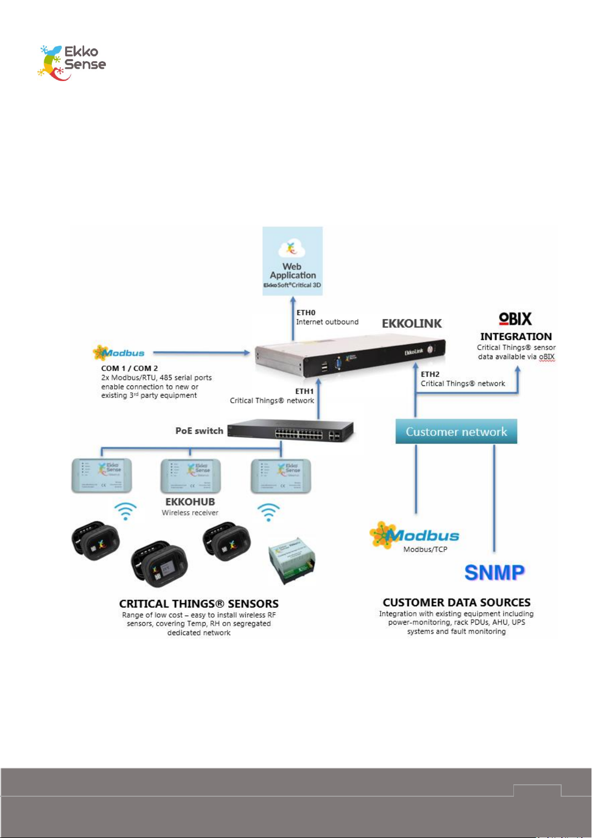
2. EkkoHub and wireless sensors
Critical Things ™ wireless sensors are designed to take accurate temperature and relative
humidity measurements from the racks in a data centre.
The sensors use radio to communicate their measurements to an EkkoHub wireless transceiver
unit. The EkkoHub receives the measurements and then sends them to the EkkoLink data
aggregator for transmission to the EkkoSoft application via an internet connection.

Critical Things ™
Wireless sensors installation guide
EkkoSense Ltd Registered in England and Wales No. 8594313 Tower House, Lucy Tower Street, Lincoln, LN1 1XW
7
3. Installation preparation
Before you install the EkkoSensors and EkkoHubs, you should make sure you have the
appropriate Tools and safety equipment. You should also make sure you are familiar with the
Installation workflow.
When you install the sensors, you need to make sure they are positioned correctly on the server
racks and that they are within range of the EkkoHub. The EkkoHub has a recommended maximum
range of 20m from EkkoSensors.
You should install the EkkoHub so that it can be connected to a Power over Ethernet switch for
power and internet connection.
Tools and safety equipment
To install the sensors and EkkoHub you will need:
Tape measure
Cable-ties
Adhesive tape
Screws and wall plugs (if fixing EkkoHub to a wall)
Ethernet cable.
Installation workflow
To install Critical Things sensors and the EkkoHub, you should follow this workflow:
1. Identify your wireless sensor
2. Connect external thermistor sensors if required (see Using thermistor inputs on
EkkoSensors)
3. Install a wireless sensor
4. Add a sensor to EkkoSoft
5. Install EkkoHub
CAUTION: Always wear appropriate Personal Protective Equipment (PPE) for the site. For
details, please contact the site manager.
Critical Things ™
Wireless sensors installation guide
EkkoSense Ltd Registered in England and Wales No. 8594313 Tower House, Lucy Tower Street, Lincoln, LN1 1XW
8
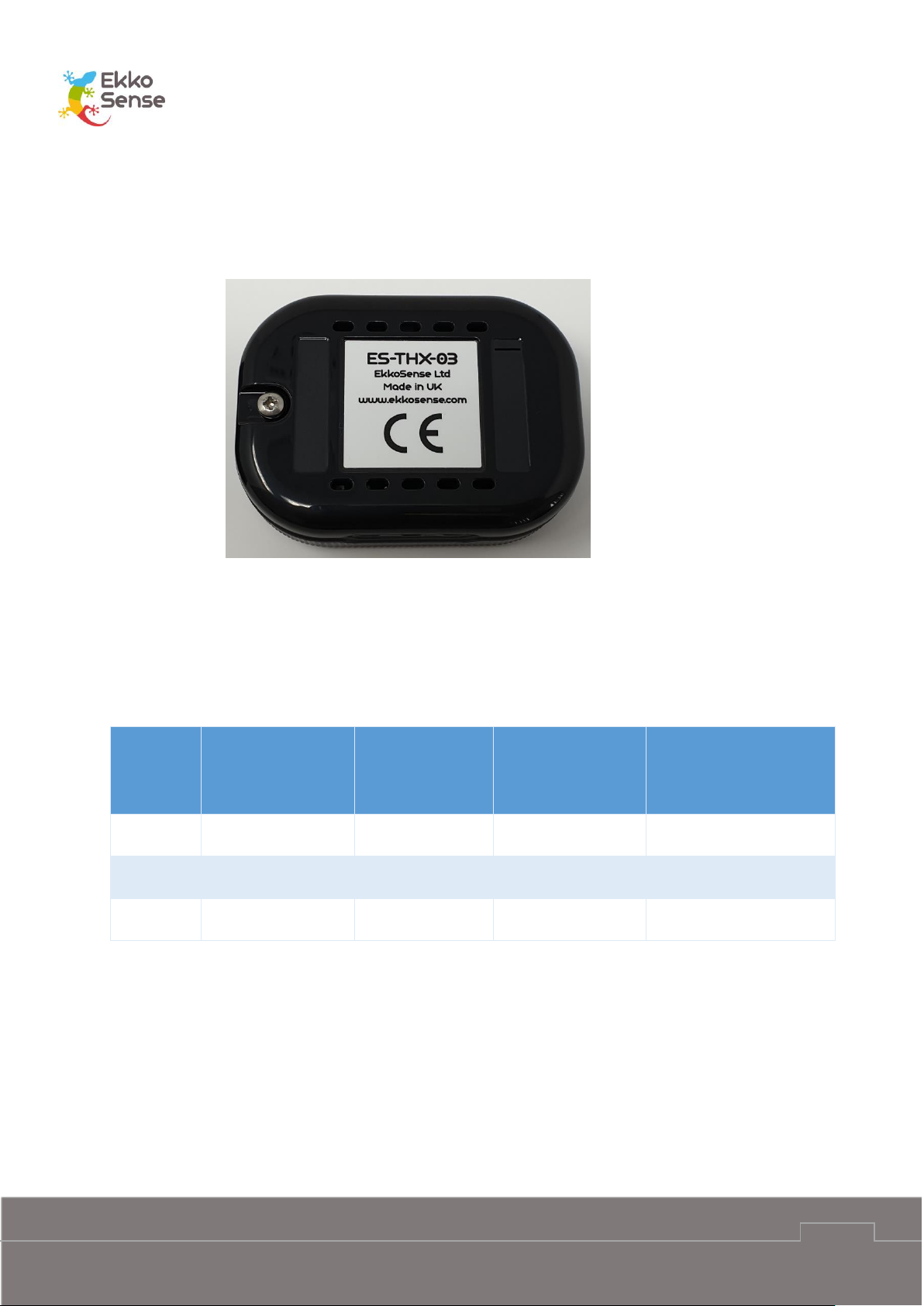
4. Identify your wireless sensor
The first step is to identify the type of sensor you have. The model is shown on the label on the
back of the sensor.
The first two characters correspond to the operating frequency. ES is 868.3MHz and FS is
923MHz. The operating frequency must match the receiving frequency of the EkkoHubs.
EkkoHubs use the same two characters to identify the receiving frequency so ES sensors and ES
EkkoHubs and FS sensors and FS EkkoHubs must be used together.
The next three characters correspond to the sensor type:
Sensor
Type
Code
Wireless
temperature
sensor
Wireless
humidity sensor
Number of
optional external
thermistor inputs
Built-in display
TSX
YES
NO
ONE
NO
THX
YES
YES
TWO
NO
TDX
YES
YES
TWO
YES
The final character is the hardware version, 03 for this version of sensors.
All sensors can support external thermistors to provide additional temperature measurements.
Some sensors support one external thermistor, others can support two. All sensors automatically
detect which external thermistors are connected and start sending the data without requiring
further configuration. More details are provided in Section 5 Using thermistor inputs on
EkkoSensors. Thermistors are commonly referred to as “flylead sensors” or “flying lead sensors”.
Critical Things ™
Wireless sensors installation guide
EkkoSense Ltd Registered in England and Wales No. 8594313 Tower House, Lucy Tower Street, Lincoln, LN1 1XW
9
5. Using thermistor inputs on EkkoSensors
The thermistor inputs on the EkkoSensors are configured for use with NTC thermistors with a
nominal resistance of 10kΩ at 25°C and a ß value of 3435K at 25/85°C. This is commonly referred
to as a Carel thermistor. Use of thermistors with other temperature characteristics will not give
accurate results.
The connection to the EkkoSensor uses a standard JST two pole HER-2 crimp housing with SHE001T-P0.6 or BEH-001T-P0.6 crimp connectors for wires with 0.05mm2 to 0.33mm2 cross
sectional area (30-22AWG) and insulation overall diameter 1.0mm to 1.9mm.
Connections between the thermistor and sensor do not need to be screened but should be 3m
or less.
EkkoSense supply a pre-assembled thermistor on 1.2m cable (EKCRSN00438) and a 3m cable with
the HER-2 connector on one end and blank the other end (EKCRSN00476) for connection to other
thermistors.
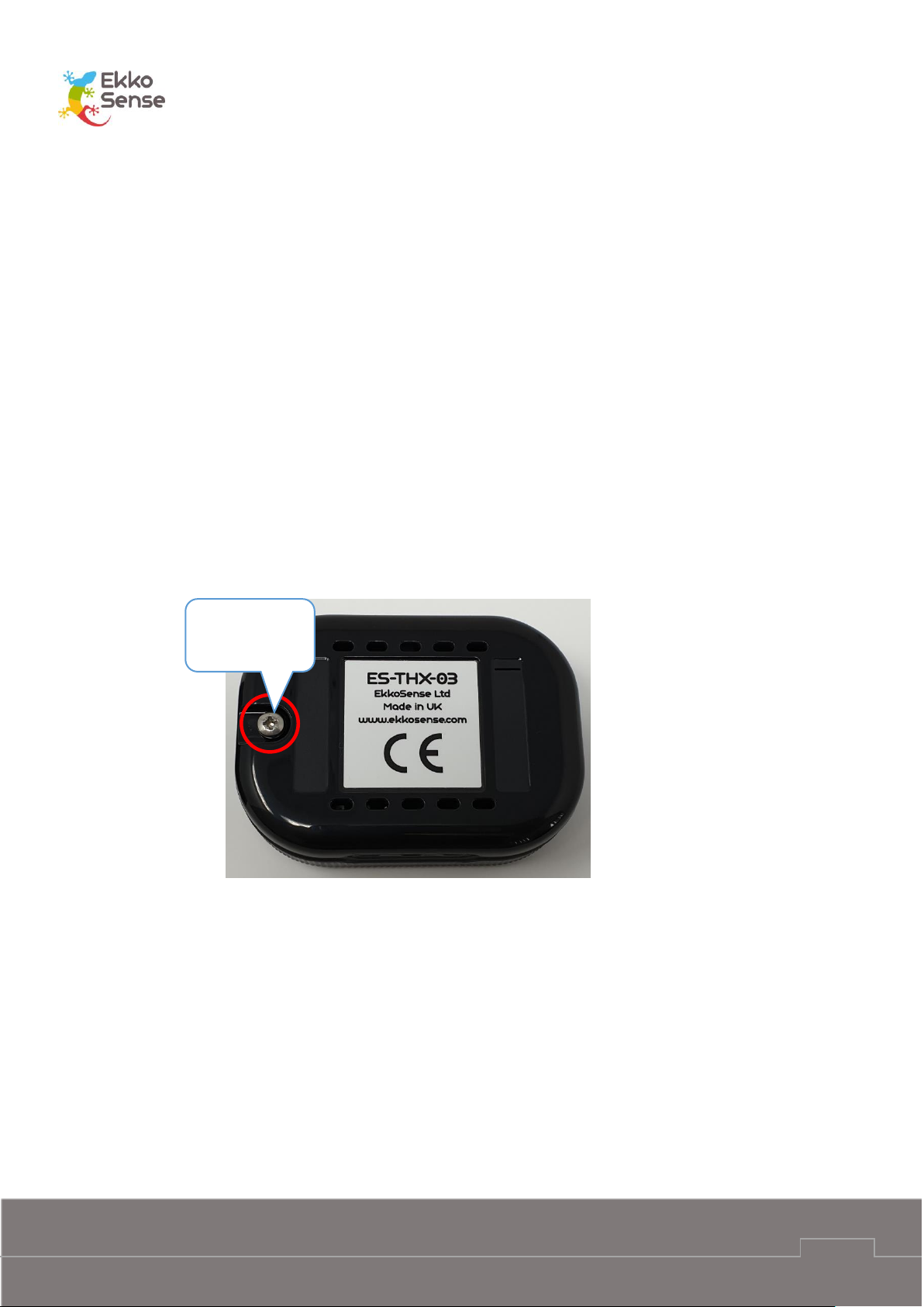
To connect a thermistor to a sensor, remove the back cover of the sensor by removing the screw.
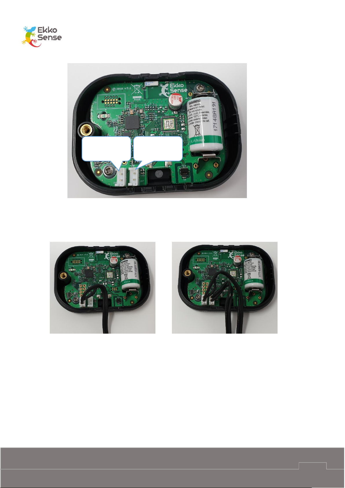
The socket(s) are shown below. The identifiers B and C correspond to the way the measurement
values are identified to the software. Care should be taken that when two thermistors are
connected that they are clearly identified as B and C and correctly configured in the software.
The temperature only sensor (TSX) has only the single connector for Sensor B.
Remove
screw
Critical Things ™
Wireless sensors installation guide
EkkoSense Ltd Registered in England and Wales No. 8594313 Tower House, Lucy Tower Street, Lincoln, LN1 1XW
10
The thermistor cable connectors push fit into the housings. When fitting the thermistors avoid
touching the circuit board. The cables can be routed out of the air vents at the bottom or top of
the sensor enclosure with examples or routing one or two out of the bottom being shown below:
Replace the sensor back by hooking it in at the right-hand side and then replacing the screw,
taking care to ensure the thermistor cables route out through the holes and are not trapped.
Sensor B
External 1
Sensor C
External 2

Critical Things ™
Wireless sensors installation guide
EkkoSense Ltd Registered in England and Wales No. 8594313 Tower House, Lucy Tower Street, Lincoln, LN1 1XW
11

Critical Things ™
Wireless sensors installation guide
EkkoSense Ltd Registered in England and Wales No. 8594313 Tower House, Lucy Tower Street, Lincoln, LN1 1XW
12
6. Install a wireless sensor
To install a wireless sensor, you need to:
1. Assess the location of the air inlets (see page 12)
2. Consider mounting requirements (see page 13)
3. Fit the wireless sensor (see page 15).
You can then Add a sensor to EkkoSoft (see page 17).
Assess the location of the air inlets
You need to determine where the air inlets are positioned for the rack. This is because the sensor
needs to be close to the air inlets and away from any equipment exhausts (outlets).
You need to determine where the air inlets are positioned for the rack. This is because the sensor
needs to be close to the air inlets and away from any equipment exhausts.
Sensors can be fitted to standard racks or racks with glass front panels. Racks with glass fronts
require a different approach, and so we have separated the two here.
Regular racks – air inlets
Ideally, all of the equipment in the rack will be facing the same direction. This will give
you a clear front and back, where the front is the side with the air inlets and the back is
the opposite side, where the exhausts are. With this type of arrangement, you will install
the sensor on the front of the rack with the optional external sensor positioned lower
down.
However, on some sites, the equipment in a rack may be facing different directions. This
can make it more difficult to position the sensor, as there is no clear front and back. With
this type of arrangement, you need to determine which side of the rack is the warmest
side. You can consider the warmest side to be the back (outlet) and the opposite side is
where you will fit the sensor (the air inlet side).
Glass-front racks – air inlets
Racks with glass fronts often have the air inlets at the bottom of the front panel or at the
sides. You will need to locate the air inlets before you can fit the sensor.

Critical Things ™
Wireless sensors installation guide
EkkoSense Ltd Registered in England and Wales No. 8594313 Tower House, Lucy Tower Street, Lincoln, LN1 1XW
13
Consider mounting requirements
The sensors are supplied with a standard mounting clip that can be cable tied to a mesh rack
front or fixed to a glass front using double sided tape. Alternatively, the sensor can be directly
mounted to a suitable surface using double sided tape. Bear in mind that this will prevent access
to the sensor in the future for battery replacement and flylead sensor installation and so it should
only be done if specifically requested. Cable ties are the preferred attachment method. The slots
in the mounting clip are 4.2mm wide and suitable for use with 2.5mm to 3.5mm wide cable ties.
Approximately 140mm length is usually convenient, for example Hellerman Tyton T18I. If it is not
possible to get access to the inside of the rack door then the cable tie can be threaded through
from the front by folding it in half to create a ‘hook’.
If double sided tape is used, then check that it is compatible with the surface the sensor is being
mounted to. Also pay attention to any surface preparation requirements to ensure reliable
adhesion. Hi-Bond VST 4100C has been used successfully in the past and is available in 6mm wide
reels (VST 4100C/1/6/10) for use on the sensors and 25mm wide reels (VST 4100C/1/25/10) for
use with the mounting clip. Tesa 64958 and 3M VHB 4952 tapes are suitable for low surface
energy (for example painted) surfaces.
Feed cable tie
through slots,
cut off excess
Extra fold in cable tie to help
insertion from front of rack
Location for double sided self-
adhesive foam tape.

Critical Things ™
Wireless sensors installation guide
EkkoSense Ltd Registered in England and Wales No. 8594313 Tower House, Lucy Tower Street, Lincoln, LN1 1XW
14
On some sites, there are special requirements that you need to consider when you fit a sensor.
Some common requests are:
Sensors cannot be fitted to front panel and have to be hidden from view
Flylead sensors must have their cable routed around the edge of the rack.
You also need to be aware of any practical limitations, such as the rack front lacking any fixtures
to attach the sensor to.
Sensors must not be located where they could block the air inlet to the rack
Location for double
sided self-adhesive
foam tape.
Location for double
sided self-adhesive
foam tape.

Critical Things ™
Wireless sensors installation guide
EkkoSense Ltd Registered in England and Wales No. 8594313 Tower House, Lucy Tower Street, Lincoln, LN1 1XW
15
Fit the wireless sensor
Having located the air inlets and considered the mounting requirements the sensor can be
installed. Some examples of suitable locations for the sensor in different situations are given in
the following table:
Rack type
Air inlets
Request
Suitable sensor position
Standard
Front
None
Sensor: Central, near inlet, 1.7m above the floor.
Flylead sensor (if used): Central, 0.5m from floor.
Standard
Front
No sensor on
front
Sensor: On top of rack.
Flylead sensor: Central, near inlet, 1.7m above the
floor.
Standard
Mixed
None
Sensor: On coolest side, near inlet, 1.7m above the
floor.
Flylead sensor: Central on same side as sensor, 0.5m
from floor.
Standard
Mixed
No sensor on
front
Sensor: On top of rack.
Flylead sensor: Central on coolest side, 1.7m above
the floor.
Standard
Mixed
No sensor on
front, two
temperature
measurements
required
Sensor: On top of rack.
Flylead sensors: Central on coolest side. One sensor
1.7m above the floor, the other sensor 0.5m above
the floor.
Glass front
Front,
bottom
None
Sensor: On top of rack.
Flylead sensor: Central, with flylead sensor secured in
place so that sensor is next to the air inlet. Secure the
flylead with tape.
Glass front
Side
None
Sensor: On top of rack.
Flylead sensor: Position down the side of the rack so
that the sensor is next to the air inlet. Secure the
flylead with tape.

Critical Things ™
Wireless sensors installation guide
EkkoSense Ltd Registered in England and Wales No. 8594313 Tower House, Lucy Tower Street, Lincoln, LN1 1XW
16
Now that you have installed the sensor, the next step is to add it to the EkkoSoft software, so
that it can be monitored (see Add a sensor to EkkoSoft on page 17).
You may prefer to install all of the sensors and then add them to EkkoSoft afterwards.

Critical Things ™
Wireless sensors installation guide
EkkoSense Ltd Registered in England and Wales No. 8594313 Tower House, Lucy Tower Street, Lincoln, LN1 1XW
17
7. Add a sensor to EkkoSoft
When you have installed a sensor, you need to add it to the Ekkosoft software so that it can be
monitored.
There are two ways to add a sensor to EkkoSoft. You can either use a 2D barcode scanner to scan
the sensor’s QR code or you can enter the scanner’s ID manually.
1. Login to EkkoSoft on a laptop (internet connection required).
2. Select the data centre.
3. Select Visit Room.
4. Select Editor mode.

Critical Things ™
Wireless sensors installation guide
EkkoSense Ltd Registered in England and Wales No. 8594313 Tower House, Lucy Tower Street, Lincoln, LN1 1XW
18
5. Select the rack that the sensor is attached to.
6. Expand the Advanced settings.
7. Select the Sensor ID field.
8. Connect a 2D barcode scanner to your laptop (via USB) and scan the sensor’s QR code.
The QR code is on the label on the front of the sensor. It is also available on the LCD screen
(ES-TDX-03 sensors only).
If you do not have a 2D barcode scanner, you can enter the sensor’s ID manually. We
recommend that you use a barcode scanner where possible, as it reduces the chances of a
scanner’s ID being mistyped.
When you scan the QR code, the sensor’s ID code is automatically copied from the 2D
barcode reader into the Sensor ID field (as long as the Sensor ID field is selected).
9. Repeat this process for each sensor that you add to the racks.

Critical Things ™
Wireless sensors installation guide
EkkoSense Ltd Registered in England and Wales No. 8594313 Tower House, Lucy Tower Street, Lincoln, LN1 1XW
19
8. Battery installation or replacement
The EkkoSensors use a Lithium Thionyl Chloride ½ AA 3.6V battery. Use only SAFT LS14250 or
Tadiran SL-750/S / TL-5902 batteries.
To get to the battery remove the sensor back cover by undoing the screw. Avoid touching the
circuit board.
Remove the battery by rolling it to the side and lifting it out.
Ensure the new battery is fitted with the correct polarity, positive to the ‘+’ symbol on the board
(the flat metal clip on the board). Fit a new battery by pushing in the negative terminal against
the spring contact first and then pushing it completely in to place.
Remove
screw

Critical Things ™
Wireless sensors installation guide
EkkoSense Ltd Registered in England and Wales No. 8594313 Tower House, Lucy Tower Street, Lincoln, LN1 1XW
20
Replace the sensor cover by hooking the right hand side into the front section and tightening the
screw.
Battery handling and storage precautions
Store batteries in a cool (preferably below 21°C and in any case below 30°C), dry and
ventilated area, away from possible sources of heat, open flames, food and drink. Avoid
exposure to direct sunlight for long periods.
Keep spare batteries in original packaging until they are ready to be installed
Do not dispose of batteries in a fire, they may leak or rupture
Do not disassemble, crush, puncture or otherwise damage batteries
Insert batteries correctly
Store used batteries as if they are new until they can be safely disposed of
Recycle used batteries if possible. Dispose of in accordance with local laws and regulations
Batteries do not contain hazardous materials according to EC Directives 91/157/EEC,
93/86/EEC, and 2002/95/EC (RoHS)

Critical Things ™
Wireless sensors installation guide
EkkoSense Ltd Registered in England and Wales No. 8594313 Tower House, Lucy Tower Street, Lincoln, LN1 1XW
21
9. Using TSX and THX sensors
The button has two functions:
• A short press triggers the sensor to send a measurement message immediately instead of
waiting for the next scheduled message. This may be useful during initial installation.
• A long press puts the sensor into configuration mode. The LED flashes briefly to indicate
that the sensor is in configuration mode. On each flash the sensor sends a special message
to indicate that it is in configuration mode and waits for a response. It does this four times
at five second intervals before returning to normal operation. Configuration mode is used
by the configuration application to change sensor reading interval or encryption key. See
the separate user guide on the configuration application for more information.
Button
LED

Critical Things ™
Wireless sensors installation guide
EkkoSense Ltd Registered in England and Wales No. 8594313 Tower House, Lucy Tower Street, Lincoln, LN1 1XW
22
10. Using the TDX sensors
The button has two functions:
• A short press moves through the different display screens. The first press moving away
from the main screen also triggers the sensor to send a measurement message
immediately instead of waiting for the next scheduled message. This may be useful during
initial installation.
• A long press puts the sensor into configuration mode. The LED flashes briefly to indicate
that the sensor is in configuration mode. On each flash the sensor sends a special message
to indicate that it is in configuration mode and waits for a response. It does this four times
at five second intervals before returning to normal operation. Configuration mode is used
by the configuration application to change sensor reading interval or encryption key. See
the separate user guide on the configuration application for more information.
The display provides with useful status information, including:
The measurements currently being taken by the sensor
Graphs showing the sensor’s measurements over time
Information about the sensor.
Button
LED

Critical Things ™
Wireless sensors installation guide
EkkoSense Ltd Registered in England and Wales No. 8594313 Tower House, Lucy Tower Street, Lincoln, LN1 1XW
23
Browse the sensor screens
To navigate between the sensor’s screens, press the button. Each time you press the button, the
next available screen is shown. If the button is not pressed for one minute the sensor returns to
the main screen.
Main screen
The main screen shows the current temperature and relative humidity measured by the internal
sensor and the temperature measured by any thermistor sensors.
At the top of the display, it shows OK or ALERT. OK is displayed when all temperature
measurement sources active for generating alerts are within the configured limits. ALERT is
displayed if one or more of the temperature measurement sources active for generating alerts
are outside the configured limits.The sensor status also shows the current temperature of the
internal sensor and the relative humidity (RH only on sensors that measure humidity).
The display units can be selected between Celsius and Fahrenheit using the configuration
application.
Normal display showing temperature and relative humidity from internal
sensor.
Alert display showing temperature and relative humidity from internal
sensor.
Normal display showing temperature and relative humidity from internal
sensor and temperature from thermistor sensor inputs. Sensor B (External
1) is the upper of the two, Sensor C (External 2) is the lower. If only one
thermistor sensor is fitted then the other display area remains blank.
Normal display in when configured for Fahrenheit.

Critical Things ™
Wireless sensors installation guide
EkkoSense Ltd Registered in England and Wales No. 8594313 Tower House, Lucy Tower Street, Lincoln, LN1 1XW
24
Thermistor temperature measurements
The next screens show the temperature measured by the thermistor sensors if fitted.
Temperature measured by first thermistor sensor (Sensor B / External 1)
Temperature measured by first thermistor sensor (Sensor C / External 2)
Compliance
The compliance screen shows the temperature range that is used to determine if the
temperature is at an acceptable level (compliant). This can be changed by the configuration
application in the range -30°C to 69°C (22°F and 156°F). It also shows which temperature
measurement inputs are included for alert generation. Again, this can be changed by the
configuration application.
Default compliance settings; low threshold 18°C (64°F), high threshold
27°C (81°F), internal sensor only active for alert generation.
Example display with all temperature measurement sources active for
alert generation.
Example display with no temperature measurement sources active for
alert generation.

Critical Things ™
Wireless sensors installation guide
EkkoSense Ltd Registered in England and Wales No. 8594313 Tower House, Lucy Tower Street, Lincoln, LN1 1XW
25
Statistics screens
The next screens show a summary of the minimum, average, and maximum temperatures that
have been measured by the internal sensor and any thermistor sensors that are installed
followed by the minimum, average and maximum relative humidity measured by the internal
sensor. There are minimum, average, and maximum values for the current hour, the current day,
and the past seven day period. The number of screens available depends on the number of
external thermistor sensors that are present. There will always be a screen for the internal
temperature measurement and the internal relative humidity measurement. The statistics are
reset if the configuration of the unit is changed.
Example screen for internal temperature sensor statistics.
Example screen for first thermistor sensor (Sensor B / External 1)
temperature statistics.
Example screen for internal humidity sensor statistics.

Critical Things ™
Wireless sensors installation guide
EkkoSense Ltd Registered in England and Wales No. 8594313 Tower House, Lucy Tower Street, Lincoln, LN1 1XW
26
Graphs
You can view the historical temperature data in a graph format on the sensor’s display. There are
three graph screens available: Last Hour, 24 Hour, and 7 Day, each providing a graph for a
different time period (last hour, last 24 hours, and last 7 days).
All temperature measurement sources that are present are included in the graph so there can be
up to three lines.
Example screen for last hour temperature measurements (internal
temperature sensor and one thermistor reading very similar
temperatures).
Example screen for last 24 hour temperature measurements (internal
temperature sensor and one thermistor showing slight difference in
response time between temperature measurements).
Sensor information screens
The final two screens provide information about the sensor.
The top line shows the sensor’s ID and the second line shows the battery
voltage. In the bottom corner, you can see the firmware details, which
should be quoted when reporting any issues about the sensor to
EkkoSense.
The QR code screen provides the same sensor ID information as printed
on the front of the sensor.
A final press completes the cycle and returns the display to the main screen.

Critical Things ™
Wireless sensors installation guide
EkkoSense Ltd Registered in England and Wales No. 8594313 Tower House, Lucy Tower Street, Lincoln, LN1 1XW
27
11. EkkoSensor specifications
Parameter
Specification
Operating temperature range
-10°C to 55°C (14°F to 131°F)
Operating humidity range
0% to 100% non-condensing
Temperature accuracy (internal
sensor)
±0.3°C typical (±0.5°F)
External inputs measurement
accuracy (excluding accuracy of
thermistor)
±0.6°C typical (±1°F)
Humidity accuracy
±2% typical from 20% to 80% RH
Temperature alerts (TDX model only)
Low and high thresholds configurable between -30°C
and 69°C (-22°F and 156°F). Alerts can be generated
by some or all temperature inputs.
Weight
51g (1.8oz), 62g (2.2oz) in clip
Dimensions
75mm x 55mm x 22mm (3” x 2.2” x 0.9”)
80mm x 58mm x 28mm (3.1” x 2.3” x 1.1”) in clip
Operating range (from EkkoHub)
> 20m (21yds)
Battery life
> 5 years at 2 minute transmit interval (TSX, THX)
> 3 years at 2 minute transmit interval (TDX)
RF data link
GFSK 250kbit/s at 868.3MHz (ES versions) or 923MHz
(FS versions)
Enclosure material
Black ABS with polycarbonate front window
Mounting method
Cable tie through clip or self adhesive pad
Power supply
Internal field replaceable ½ AA lithium thionyl
chloride battery

Critical Things ™
Wireless sensors installation guide
EkkoSense Ltd Registered in England and Wales No. 8594313 Tower House, Lucy Tower Street, Lincoln, LN1 1XW
28
Parameter
Specification
Regulatory approvals (ES version)
CE marked:
Radio Equipment Directive (RED) 2014/53/EU
Low Voltage Directive (LVD) 2014/35/EU
Radio EN 300 220
EMC EN 61326-1 with reference to EN 301 489
Safety - EN 60950
Regulatory approvals (FS version)
FCC rules CFR 47 Part 15.107 and 15.109 Class A
FCC rules CFR 47 Part 15.247

Critical Things ™
Wireless sensors installation guide
EkkoSense Ltd Registered in England and Wales No. 8594313 Tower House, Lucy Tower Street, Lincoln, LN1 1XW
29
12. Install EkkoHub
The EkkoHub wireless transceiver unit receives the data messages from Critical Things ™ wireless
sensors (EkkoSensors, EkkoAirs) and sends them to the EkkoLink data aggregator.
To install an EkkoHub unit:
1. Find a suitable position for the EkkoHub (see page 29).
2. Fit the EkkoHub transceiver unit (see page 30).
Find a suitable position for the EkkoHub
Before you install an Ekkohub transceiver unit, you need to locate a suitable position in the room.
The things you need to consider are:
The EkkoHub can be positioned in any orientation, but the front needs to be facing
outwards so that the LEDs can be seen.
The EkkoHub has to be positioned at less than 20m from the wireless sensors.
The front panel of the EkkoHub should not be positioned on or next to metal.
For best performance, you should fit the EkkoHub so that it has clear space around it,
with only its rear in contact with a surface.
The EkkoHub needs to be connected to a Power over Ethernet switch for power and
data connection.

Critical Things ™
Wireless sensors installation guide
EkkoSense Ltd Registered in England and Wales No. 8594313 Tower House, Lucy Tower Street, Lincoln, LN1 1XW
30
Fit the EkkoHub transceiver unit
When you have identified a suitable location, you can fit the EkkoHub unit.
1. Open the side sections on the EkkoHub to reveal four mounting holes (two holes per side).
2. Feed cable ties through the holes and secure the EkkoHub to a cable basket. Alternatively,
you can drill holes in the wall and fit screws through the holes in the Ekkohub casing to
fix the EkkoHub in place. Insert wall plugs into the holes in the wall before screwing the
EkkoHub into position.
3. Connect the EkkoHub to the Power over Ethernet switch via an Ethernet cable. When you
make the connection, the EkkoHub’s Power LED should light up, followed by the Network
LED.
Note: The USB port can be used to connect to a laptop for changing the EkkoHub
configuration. In this case the EkkoHub will draw power from the USB host device and
does not need the Ethernet connection.
USB
Ethernet

Critical Things ™
Wireless sensors installation guide
EkkoSense Ltd Registered in England and Wales No. 8594313 Tower House, Lucy Tower Street, Lincoln, LN1 1XW
31
13. EkkoHub LEDs
The EkkoHub has four status LEDs.
LED
Function and expected status
Power
Flashes to indicate that the EkkoHub is receiving power. This must be
Illuminated for the hub to work. If the LED does not light then check
the cabling between the hub and the PoE switch and check that the PoE
switch is powered
Network
Illuminates continuously to indicate that the EkkoHub has a connection
to the EkkoLink. This must be Illuminated for the EkkoHub to work.
If the LED does not light then check the cabling to the PoE switch. If the
EkkoLink has custom configuration then check that the EkkoHub has
been configured to match this.
Transmit
Not used. Reserved for future development.
Receive
Toggles state from dark to illuminated and vice versa every time a data
packet is received from a sensor. If there is no activity then check that
the hub is correctly configured for the sensors (Operating Frequency ES or FS, Encryption Key).

Critical Things ™
Wireless sensors installation guide
EkkoSense Ltd Registered in England and Wales No. 8594313 Tower House, Lucy Tower Street, Lincoln, LN1 1XW
32
14. FCC Statement
The EkkoSense wireless sensors and EkkoHub comply with part 15 of the FCC Rules.
Operation of EkkoSense wireless sensors and EkkoHub is subject to the following two conditions:
1. This device may not cause harmful interference, and
2. This device must accept any interference received, including interference that may cause
undesired operation.
CAUTION: Changes or modifications to the products that are not expressly approved by
EkkoSense Ltd could void the user’s authority to operate the equipment.
 Loading...