

EKKO EK20R, EK20RL User Manual
EK20R(EK20RL)
Electric Counterbalanced Forklift
Manual

Note Please read this manual before using!
Note Please do not use it before completing the installation!
Aug.2018

Introduction
In order to meet the needs of the national environmental protection request,
To reduce industrial pollution and improve productivity, we design and produce
new series of EK20R(EK20RL) type Counterbalanced forklift on the basis of
absorption of the advantages of domestic & overseas Electric forklift ,they are
especially suitable for cargo loading and unloading, handling, stacking, etc for
food, bank, light textile, station, port, logistics and other enterprises. And it can
apply widely if inter-grate with different fixture
The Electric forklift adopt wild-field lifting system ,EPS system , new AC
controller and Open type lamp holder .It is equipped high-quality Motors, Battery,
and high-power pumping stations .Therefor it is Convenient operation .With
Good view, Flexible steering ,Reliable braking ,Good power, Low noise, No
pollution and Attractive appearance .
This manual describes the technical parameters of the Counterbalanced
Electric Forklift , working principle and operation, maintenance, and other
aspects. It can help operators use the Counterbalanced Electric Forklift more
reasonable, make its maximum effect.
It is hoped that Operator strictly abide the regulations and the precautions
in this manual when using the machine. Carefully use them so that your Forklift
can be in the best working condition for long period of time to maximize its
effectiveness. And create better economic benefits.

The Statement
Our company production model EK20R(EK20RL) type Counterbalanced
Electric Forklift is a special motor vehicle used in Factory ,Tourist
attractions ,Amusement places which is specified by “special equipment safety
supervision regulations”
Contents

1.General Introduction ............................................................................................ 1
2.Proper usage ............................................................................................................ 2
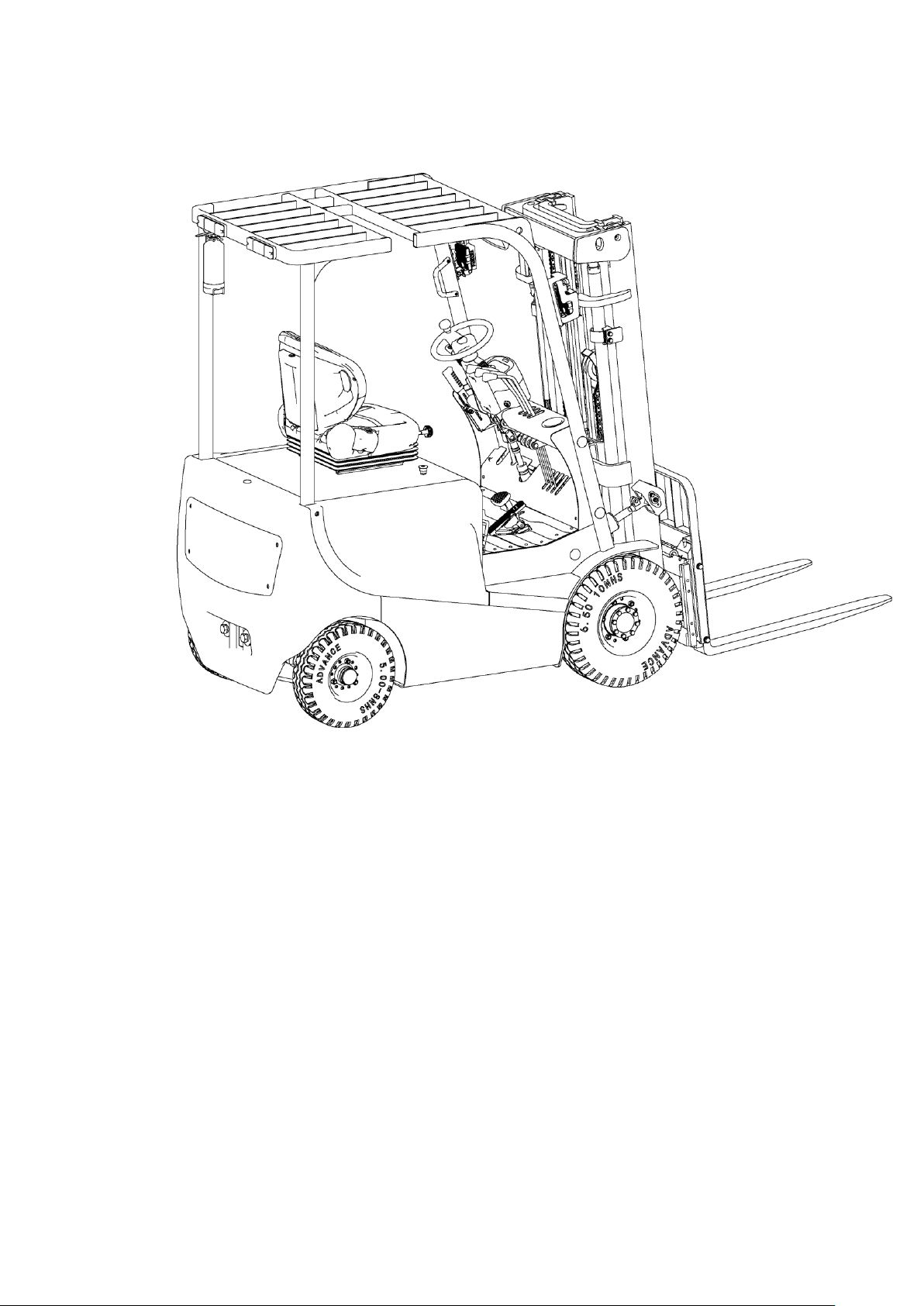
3..Introduction of the product ............................................................................... 4
3.1Model overview ............................................................................................................ 4
3.2Product Schematic diagram&Parameter ............................................................ 4
4.The Schematic diagram of Operating Mechanism ...................................... 5
5.Structure ,Principle and Adjustment of main parts of forklift ............... 7
5.1Drive system .................................................................................................................. 8
5.2Steering system ............................................................................................................ 9
5.3 Brake structure &Brake Schematic .................................................................... 12
5.4 Operating system ...................................................................................................... 21
5.5 Electric system ........................................................................................................... 22
5.6 Hyraulic system ......................................................................................................... 24
6.Electrical Schematic diagram .......................................................................... 25
7.Hydraulic Schematic diagram ......................................................................... 26
8.Operating Specification ..................................................................................... 27
8.1 Sart ,Running and Parking .................................................................................. 27
8.2 Steering wheel angle front and rear adjustment .......................................... 28
8.3 Pedal accelerator operation .................................................................................. 28
8.4 Pedal brake operation ............................................................................................. 28
8.5Use of emergency power off safety switch ...................................................... 28
8.6 Use of Horn and Reversing horn ......................................................................... 28
8.7 Hydraulic joystick operation ................................................................................ 29
8.8 Battery display ........................................................................................................... 29
8.9 Handling & Stacking operation ............................................................................ 29
9.Maintain Introduction ....................................................................................... 30

9.1 Repair & Maintenance Safety procedure ......................................................... 30
9.2 Routine Maintenance .............................................................................................. 31
9.3 Professional Maintenance manual ..................................................................... 31
9.4 Maintenance ,Recharging and replacement of the Accumulator ........... 34
10.Safety Operation And Cautions .................................................................... 42
10.1General Rul ................................................................................................................ 42
10.2 Transportation & Storage ................................................................................... 42
10.3 Check before using................................................................................................. 43
10.4Safety Operation Rules .......................................................................................... 43
11.Toubleshooting .................................................................................................. 46
11.1Hand and foot brake common faults and troubleshooting ................... 46
11.2Steering system common faults and troubleshooting ............................ 47
11.3Lifting system common faults and troubleshooting 48
11.4Electric system common faults and troubleshooting ............................. 49
11.5Gearbox failure reasons and troubleshooting.............................................. 50
11.6Multi-way valve failure reasons and troubleshooting ............................ 50
11.7Gear pump failure reasons and troubleshooting ........................................ 52
11.8Other common faults and troubleshooting ................................................... 54
12.Aftersales ............................................................................................................. 55
1
1、General Introduction
EK20R(EK20RL) type 4 wheel Counterbalanced Electric Forklift adapts
battery as the power source ,uses the AC motor as the power to drive the device
through the gear transmission. The lifting and tilting of the fork are driven by the
DC motor and Hydraulic drive to push the cylinder to lift the cargo. Because the
device is using Power to travelling & lift ,Forward & back tilting and side shift.
therefor it is Low effort, High efficiency, Stable cargo operation. Simple operation,
Safe and reliable .Low noise & No pollution
The biggest advantage for 4wheel counterbalanced electric forklift is that it
is adopt optimized design ,wide-view mast, the mast and rubber tube pulley
block are more compact .It is not easy to block the operator’s sight. The size of
the fork frame is increased, and the field of view is wide .Large arc roof
guard ,The best angle of the grid to increase the driver’s upper view .The
right-hand control handle fully reflects ergonomics ,Improves the comfort of
handling and reduces the labor intensity of the operator .

2
The device is suitable for Stacking & Handling cargo on firm ,flat floors
The service environment:
a. Altitude does not exceed 1200m;
b. Indoor room temperature at +5℃ to +40℃ ;
c. When environment temperature at +40℃,the relative humidity can’t
over 50%,at low temperature ,allow bigger relative humidity
d. Firm, Flat ground 。
e. It is forbidden to use this car in corrosive environment such as flammable
and explosive or acid base.
2、Proper use
Please using the Counterbalanced electric forklift according to this
specification.
The Forklift described in this manual is a self-controlled series of
Counterbalanced Electric forklift. With Multi-way valve control forklift
lifting ,forward backward tilting ,side shifting etc function.
Improper use can cause personal injury or machine damage. Operators or
operating companies need to ensure proper using, make sure that the truck is
operated only by personnel who are trained and authorized to use the truck.
The Truck needs to be used on a firm ,flat ,intact surface and suitable
surface ,the truck is designed for indoor use at room temperature from+5°C to
+40°C
Use under light load without using permanent barriers or pits ,It is
forbidden to operate on the slope .During Operation ,The goods must be placed
approximately at the center of the truck’s load center
Lifting or Carrying people is strictly prohibited ,if carried goods .The goods
must fall on the lifting point 。
It is prohibited to use this truck on lifting or loading ramps。
The rated capacity is marked on the capacity label or nameplate. And the
operator must pay attention to the warming signs and safety instructions

3
Operating lighting must be at lest 50LUX
Modification
Any modification that may affect the truck rated capacity, stability, or safety
operations must be approved in advance by the Truck’s original manufacturer
or Its authorized Manufacturer or its successor. This includes the effects of
changes such as Braking ,steering ,Visibility, and the addition of removable
accessories.
After the manufacturer or its successor approves the modification or
change ,The capacity name plate ,Label, identification marks, operation and
maintenance manual must be changed accordingly
Truck damage caused by not following Instruction will lose its
warranty
4
3、Introduction of the product
3.1Model overview
This manual is a collection of EA type 1.6T counterbalanced Electric forklift
(Hereinafter referred to as Forklift )
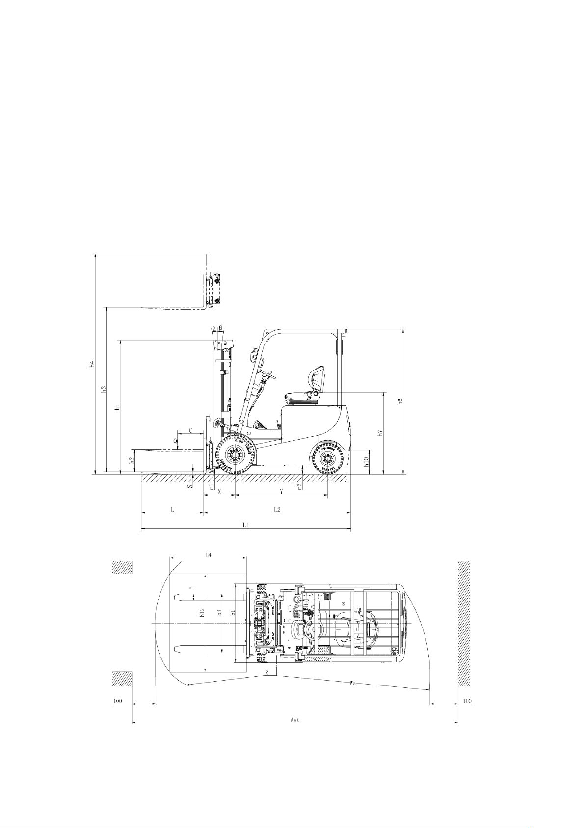
3.2Product Schematic diagram & Parameter

5
Model
EK20RL
EK20R
Power
Electric
Electric
Operator type
Rider
Rider
Load capacity
Q (lbs)
4500
4500
Lift height
h3 (in)
189
216
Load center
c (in)
20
20
Distance between fork
x(in)
18.8
18.8
Wheel base
y (in)
55.5
55.5
Service weight(include
(lbs)
7500
8000
Tires
solid tire
solid tire
Front
6.5-10-10P
6.5-10-10PR
Rear
5.0-8-14PR
5.0-8-14PR
Wheel number,Front/Rear
2×/2
2×/2
Front wheel base
b10 (in)
35
35
Rear wheel base
b11 (in)
36.2
36.2
Mast tilt Forward/backward
a/b (°)
3/6
3/6
Lowered mast height
h1 (in)
84
93
Free lift height
h2 (in)
50
60
Extended mast height
h4 (in)
221
249
Over guard height
h6 (in)
86.5
86.5
Seat height
h7 (in)
47
47
Towing pin height
h10 (in)
14
14
Overall length
l1 (in)
129
129
Body length
l2 (in)
85.4
85.4
Overall width
b1/ b2 (in)
42
42
Fork size
s/e/l (in)
1.4/3.94/4
1.4/3.94/45.2
Width of fork
b3 (in)
36.2
36.2
Floor clearance under mast
m1 (in)
4.5
4.5
Ground clearance ,centre of
m2 (in)
4.9
4.9
Aisle width for pallets
Ast (in)
165
165
Aisle width for pallets
Ast (in)
169
169
Turning radius
Wa (in)
84.6
84.6
Travel speed,
(M/h)
7.5/9
7.5/9

6
Lifting speed Laden/unladen
(in/s)
9.9/16
9.9/16
Lowering speed
(in/s)
9.5/10.2
9.5/10.2
Max gradient performance
(%)
12/15
12/15
Service brake
Hydraulic
Hydraulic
Driving motor
(kW)
7.5
7.5
Lifting Motor
(kW)
7.7
7.7
Battery, According to DIN
no
no
Battery Voltage/Capacity
(V/Ah)
48/420
48/420
Battery weight(±5%)
(lbs)
1500
1500
Battery size
(in)
30/25.6/19
30/25.6/19.6
Type of drive unit
AC
AC
Sound pressure level at the
(dB(A))
70
70
Steering type
Hydraulic
Hydraulic
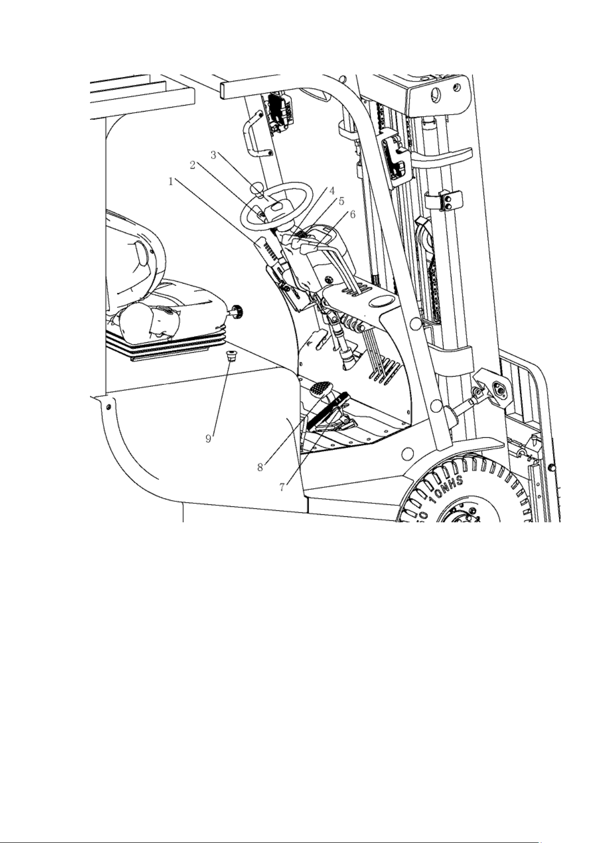
4、The Schematic diagram of Operating Mechanism
The Forklift uses battery as power source ,uses electric and hydraulic to
travelling ,& Lifting, Forward & backward tilting and steering Operating
Mechanism diagram:
7
1. Hand braking 2.Combination switch 3.Steering wheel
4.Lifting handle 5.tilting handle 6.Side shift
handle 7.Accelerator 8.Foot brake
9.Emergency stop switch
5、Structure ,Principle and Adjustment of main parts of
forklift

8
5.1Drive system
5.1.1Overview
The forklift is powered by batter and use a frequency conversion system to
convert direct current into Alternating current by controlling the AC motor on
the driving wheel . The AC motor converts the high speed and low torque to
the low speed and high torque through the gear reducer ,And the driving wheel
performs the action. The travel speed is controlled by frequency conversion
motor speed .which is controlled by accelerator
5.1.2Reducer casing
The reducer casing is located between the transaxle and the traveling motor.
The two pairs of cylindrical helical gears reduce the rotational speed from the
output shaft of the traveling motor and increase the torque transmitted from
the transmission shaft .and then transmit this torque to the differential.。
Reducer casing
1. Reducer casing body 2.Washer 3. Spring washer 4.Bolt
5.Bolt 6.Hexagon nut 7.Flat washer 8. Spring
washer 9.Washer 10.bolt 11. Flat washer
12.Spline housing 13.Adjust gasket unit 14.Sign of
mechanical transmission 15. Bolt 16.Spiral bevel gear
17.Round nut 18.Tab Washer for Round nut
2. 19. Spring washer 20.Gasket unit 21. Gasket unit 22.
Bearing seat 23.Bearing 24.Bushing 25.Oil seal
9
26.Bearing 27.Bearing cover 28.Head bolt 29.
Spring washer 30. O-Ring 31.Pad
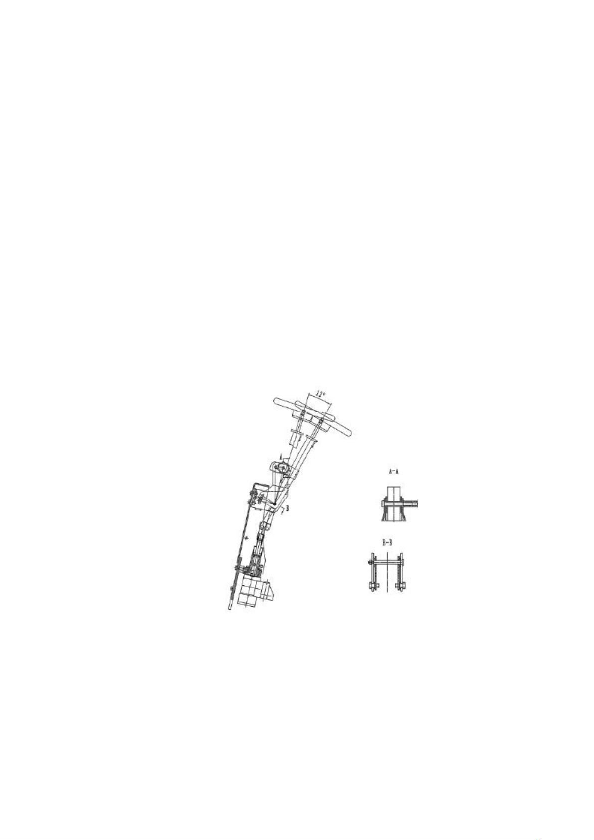
5.2Steering system
5.2.1Overview
Steering system is composed of steering wheel .Steering shaft ,Steering gear,
Steering pump0 and steering axle .The steering shaft is connected to the steering
gear through the universal joint, And the connecting shaft is connected to the
steering wheel through the universal joint ,The steering Column can be tilted
back and forth to an appropriate position. And the steering axle is mounted on
the tailstock at the rear of frame .And there is a steering on the left and the right
respectively .The steering cylinder is pushed by the steering cylinder piston rod
through the connecting rod to deflect the steering wheel to realize steering .
Steering device
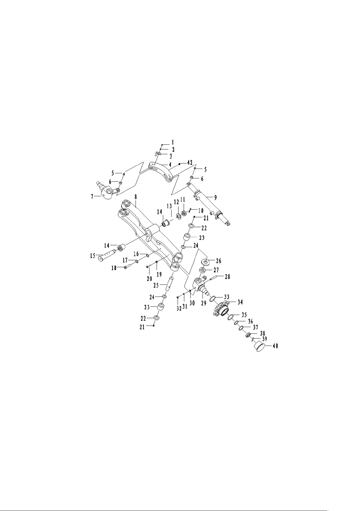
5.2.2Steering axle
Steering axle is a box-shaped cross-section welded structure composed of
steering axle body ,steering cylinder ,connecting rod,steering joint and steering
wheel.The steering trapezoid adopts a crank slider mechanism and the cylinder
10
piston rod pushes the steering joint through the connecting rod to deflect the
steering wheel .then realizing steering . The steering axle is fixed to the tailstock
at the rear of the frame by the front and rear pins through the fixing plate ,That is,
the vibration damping pad ,So that the axle body can swing around the pin
shaft .There is on joint on the left and right sides of the steering axle .and two
tapered rollers on the rear hub. The bearing is mounted on the joint shaft .The
wheel is fixed to the hub by the rim .And the inside bearing is provided with an
oil seal to keep grease in the hub .and the steering joint cavity
1.Bolt M16×12 2.Spring washer 6 3.tighten pin
4.Connecting rod
5.Joint bearing 6.Bushing 7.Left joint
8.Steering axle body
9.Steering cylinder 10.cotter 5×50 11.Groove nut
12.Flat whasher27
13.Adjust Washer 14.Bearing 15.Pin roll
16.Flat whashe12

11
17.Spring washe12 18.BoltM12×40 19. Nut M10×1.25
20.Bolt M10×1.25×40 21.Bent neck grease nipple M6 22.Oil seal
23.Bearing
24. O-ring 25.8×1.8 25.Steering joint kingpin 26.steering joint adjust
washer 27.Bearing 28.set pin 29.Right
joint 30.Washer 8 31.O-Ring32. Nut M8×1.25
33.Framework oil seal 34.Steering hub 35.Bearing
36Bolt M8×18 37.Flat whasher24 38. Nut M24×2
39.Cotter 5×45 40.Wheel hub cover
5.2.3 Adjustment ,Maintenance essential
(1) As the picture shows, Grease the inner cavity of the hub, the inner and
outer bearings and the hub cap, and also apply some grease to the lip of the oil
seal.
(2) Fixing the outer ring of the bearing to the hub and attaching the hub to
the steering joint shaft .
(3)Install the flat washer and tighten the castle nut with a torque of
206-235n.m(21-24kgm),loosen the slotted nut and then screw the nut back, the
torque is 9.8n.m(1kgm)
(4) Gently tap the hub with a wooden hammer and turn the hub 3-4 turns to
ensure that the hub is not loose.
(5)Tighten the Castle nut so that the slot is aligned with the opening pin hole
on the Knuckle
(6) Then Tap the hub with a wooden hammer and turn hub 3-4 turns by
hands to ensure smooth rotation and measure the torque of the hub, the value is
2.94-7.8N.m(0.3-0.8kgm)
(7) When the turning torque is higher than the specified value ,It can be
retracted 1/6 turn, and then measure its rotational torque
(8) When reach the specified torque .Then lock the slot nut with a split pin .
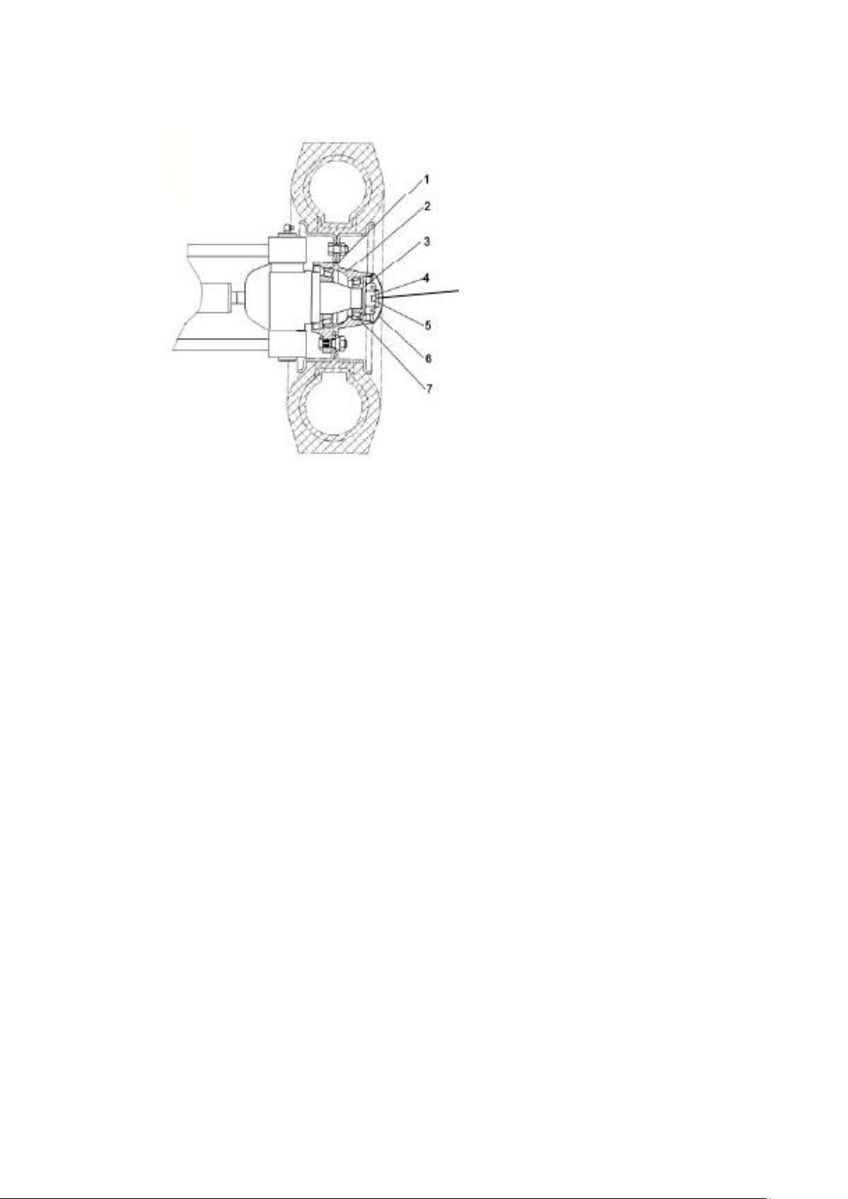
12
Preload adjustment
5.2.4 Check after reinstallation of steering system
(1) Turn the steering wheel from side to side and see whether the forces are
even, and the rotation is steady .
(2)Check weather the oil pressure pipe is arranged correctly, and weather
the left and right steering is installed in reverse .
(3) Lift the rear wheel .slowly turn the steering wheel left and right .and
repeat it several times to remove the air from the hydraulic lines and cylinders .
5.3 Braking system and schematic diagram.
5.3.1overview
The brake mode of the forklift consists of two type: service brake and
parking brake .
The service brake refers to the braking method used by the forklift during
the operation, Brake with foot brakes
When the brake cylinder pumps the brake drum to the same force as the
main brake shoe and the auxiliary brake shoe until the upper end of the brake
Inject grease

13
shoe is pressed against the fixed pin ,the brake shoe moves in the direction of
the brake drum. After the fixed pin is pressed ,the frictional force between the
friction lining and the brake drum is increased. Because the main brake shoe
gives the auxiliary brake shoe a much greater pressure than the brake cylinder
pressure ,thereby generating a large braking force .
The parking brake is mainly used in the parking state to prevent accidents
caused by slopes. A parking switch is mounted on the parking brake .and the
control circuit is disconnected in the parking The stop brake must be released
before the forklift starts to walk ,and the control circuit can be
connected .Parking brake has the function of adjusting tightness .
5.3.2Brake pedal
The brake pedal portion is constructed as shown in the figure ,and the pedal
converts in the pedaling force acting on the pedal into the brake oil pressure by
the push rod of the master cylinder .
1.Brake oil cup 2.Brake pedal 3.Brake master Cylinder 4.brake
support 5.limit bolt 6.brake sensor
5.3.3 Brake master cylinder
The master cylinder includes a valve seat ,a check valve, a return spring ,and
a main cup, piston and auxiliary cup. The master cylinder piston is actuated by
the operating brake pedal through the push rod, when the brake pedal is
depressed ,the push rod pushes the piston forward .and the brake fluid in the
pump body flows back to the oil storage tank through the oil return port until the
main the cup stops the oil return hole .After the main cup is pushed over the oil
return port .The brake fluid in the front chamber of the main pump is
compressed and the check valve is opened to flow through the brake line to the
sub -Pump.in this way ,each of the sub-pump pistons protrudes outward ,so that
the brake shoe friction plate and the brake drum are in the contact with each
other to achieve the effect of deceleration of braking .At this time ,The rear
chamber of the piston is replenished by the brake fluid from the oil return port
and the oil inlet port .When the brake pedal is released ,the piston is pressed
back by the return spring and the brake fluid in each brake cylinder is also
compressed by the brake shoe return spring .so that the brake fluid returns to
the original position. The brake fluid in the master cylinder flows back to the oil
storage tank through the oil return port .The pressure of the check valve is
adjusted to a certain ratio with the residual pressure in the brake line and the
 Loading...