

Ekinex EK-EQ2-TP Applications Manual

Application manual
KNX room temperature controller
EK-EQ2-TP

Application manual
KNX room temperature controller EK-EQ2-TP
Index
Foreword ............................................................................................................................................................. 6
1 General information ....................................................................................................................................... 6
1.1 Function ................................................................................................................................................. 6
1.2 Main funcional features .......................................................................................................................... 6
1.3 Technical data ........................................................................................................................................ 7
1.4 Design .................................................................................................................................................... 7
1.5 Delivery .................................................................................................................................................. 8
1.6 Accessories ............................................................................................................................................ 8
1.7 Marks and certification ........................................................................................................................... 8
2 Installation ...................................................................................................................................................... 9
2.1 Connection ............................................................................................................................................. 9
2.1.1 Connection of the bus line .............................................................................................................. 9
2.1.2 Connection of the inputs ................................................................................................................ 9
3 Configuration and commissioning ............................................................................................................... 11
3.1 Configuration ........................................................................................................................................ 11
3.1.1 Tree structure of the application program .................................................................................... 11
3.1.2 Languages of the application program ......................................................................................... 12
3.2 Commissioning .................................................................................................................................... 13
3.2.1 Displaying physical address and firmware release ...................................................................... 13
4 User interface .............................................................................................................................................. 15
4.1 LCD-display ......................................................................................................................................... 15
4.1.1 Information displaying .................................................................................................................. 15
4.1.2 Segment test ................................................................................................................................ 16
4.1.3 Backlight ....................................................................................................................................... 17
4.2 Rockers ................................................................................................................................................ 17
5 Sensors ........................................................................................................................................................ 18
5.1 Temperature sensor ............................................................................................................................. 18
5.2 Relative humidity sensor ...................................................................................................................... 18
6 Input variables ............................................................................................................................................. 19
7 Application program for ETS ....................................................................................................................... 20
7.1 About EK-EQ2-TP ................................................................................................................................ 20
7.1.1 General ......................................................................................................................................... 21
7.1.2 Parameters ................................................................................................................................... 21
7.2 Internal sensors ................................................................................................................................... 23
7.2.1 Parameters ................................................................................................................................... 23
7.2.2 Temperature sensor ..................................................................................................................... 23
7.2.2.1 Parameters and communication objects ................................................................... 23
7.2.3 Relative humidity sensor .............................................................................................................. 25
7.2.3.1 Parameters and communication objects ................................................................... 25
7.3 Inputs ................................................................................................................................................... 27
Release 3.00 - Updating: 27/06/2017 Application Manual
© SBS S.p.A. - All rights reserved Page 2

Application manual
KNX room temperature controller EK-EQ2-TP
7.3.1 Input X .......................................................................................................................................... 27
7.3.2 Parameters and communication objects ...................................................................................... 27
7.4 External sensors (from bus) ................................................................................................................. 31
7.4.1 Parameters and communication objects ...................................................................................... 31
7.5 Weighted temperature value ................................................................................................................ 34
7.5.1 Parameters and communication objects ...................................................................................... 34
7.6 LCD-display ......................................................................................................................................... 36
7.6.1 Parameters ................................................................................................................................... 36
7.7 Leds ..................................................................................................................................................... 38
7.7.1 Parameters and communication objects ...................................................................................... 38
7.8 Temperature control ............................................................................................................................. 40
7.8.1 Settings ........................................................................................................................................ 40
7.8.1.1 Parameters and communication objects ................................................................... 40
7.8.1.2 Heating/cooling switchover ....................................................................................... 43
7.8.1.3 Valve protection function ........................................................................................... 44
7.8.1.4 Remote Setpoint modification ................................................................................... 44
7.8.1.5 Remote operative mode modification ....................................................................... 45
7.8.2 Heating ......................................................................................................................................... 47
7.8.2.1 Parameters and communication objects ................................................................... 47
7.8.3 Cooling ......................................................................................................................................... 52
7.8.3.1 Parameters and communication objects ................................................................... 52
7.8.4 Main and auxiliary ventilation ....................................................................................................... 57
7.8.4.1 Parameters and communication objects ................................................................... 57
7.8.4.2 Delayed fan start (“hot-start”) function ...................................................................... 60
7.8.4.3 Antistratification function ........................................................................................... 60
7.8.4.4 2-stage configuration with fan-coils as auxiliary stage .............................................. 60
7.8.4.5 Remote fan speed modification................................................................................. 61
7.8.5 Scenes ......................................................................................................................................... 63
7.8.5.1 Parameters and communication objects ................................................................... 63
7.9 Relative humidity control ...................................................................................................................... 65
7.9.1 Dehumidification ........................................................................................................................... 65
7.9.1.1 Parameters and communication objects ................................................................... 65
7.9.2 Humidification ............................................................................................................................... 67
7.9.2.1 Parameters and communication objects ................................................................... 67
7.10 Comfort ................................................................................................................................................ 68
7.10.1 Comfort area ................................................................................................................................ 68
7.10.1.1 Parameters and communication objects ................................................................... 68
7.10.2 Calculated psychrometric values ................................................................................................. 69
7.10.2.1 Parameters and communication objects ................................................................... 69
7.11 Energy saving ...................................................................................................................................... 71
Release 3.00 - Updating: 27/06/2017 Application Manual
© SBS S.p.A. - All rights reserved Page 3

Application manual
KNX room temperature controller EK-EQ2-TP
7.11.1 Window contacts .......................................................................................................................... 71
7.11.1.1 Parameters and communication objects ................................................................... 71
7.11.2 Presence sensors ........................................................................................................................ 72
7.11.2.1 Parameters and communication objects ................................................................... 72
7.11.3 Card holder ................................................................................................................................... 73
7.11.3.1 Parameters and communication objects ................................................................... 73
7.12 Additional warnings .............................................................................................................................. 75
7.13 Logic functions ..................................................................................................................................... 76
7.13.1 Parameters and communication objects ...................................................................................... 76
8 List of communication objects ..................................................................................................................... 78
9 Regulation algorithms .................................................................................................................................. 81
9.1.1.1 Two-point control with hysteresis .............................................................................. 81
9.1.1.2 Continuous Proportional-Integral control .................................................................. 83
9.1.1.3 PWM Proportional-Integral control ............................................................................ 84
9.1.1.4 Fan-coil with ON-OFF fan speed control .................................................................. 86
9.1.1.5 Fan-coil with continuous speed control ..................................................................... 88
9.1.1.6 2 points control with hysteresis for auxiliary stage .................................................... 90
9.1.1.7 Auxiliary stage with fan-coil ....................................................................................... 90
10 Diagnostics .................................................................................................................................................. 92
11 Warnings ...................................................................................................................................................... 93
12 Other information ......................................................................................................................................... 93
Release 3.00 - Updating: 27/06/2017 Application Manual
© SBS S.p.A. - All rights reserved Page 4

Application manual
Revision
Updating
Date
3.00
ETS application version: VER 3.00.
Modified and/or added features:
Communication object 101 Building protection HVAC mode active
Communication object 102 Fan manual speed percentage
Communication object 103 Fan manual speed off status
Brightness sensor and corresponding functionalities removed
27/06/2017
2.00
ETS application version: VER 2.00.
Modified and/or added features:
Heating/cooling status out and Heating/cooling status in communication objects (more enhanced
management)
Communication objects for operating modes’ remote control, setpoint temperature and auto/manual
mode of fan
Logic functions AND, OR, EXOR, 4 inputs, 8 channels
20/06/2016
1.00
Emission
02/04/2015
KNX room temperature controller EK-EQ2-TP
The latest revision of the application manual is available at www.ekinex.com. For previous revisions, contact
the technical support at support@ekinex.com.
Release 3.00 - Updating: 27/06/2017 Application Manual
© SBS S.p.A. - All rights reserved Page 5

Application manual
KNX room temperature controller EK-EQ2-TP
Foreword
The present document describes the ekinex
®
KNX room temperature controller with LC-display (EK-EQ2-TP
version).
1 General information
The device described in the present document works as an electronic digital temperature controller for a
room or a zone (consisting e.g. in a group of rooms or a whole floor) of a building and is part of the
secundary regulation for heating and cooling. The room temperature controller has been developed
according to the KNX standard for use in systems of control of homes and buildings.
Through the integrated sensors, the device can measure directly in the room the temperature and relative
humidity values that can be used for control and regulation tasks of heating, cooling and ventilation. Via the
bus the device can furthermore receive temperature, relative humidity and CO
other bus devices. The integrated display visualizes a series of information concerning the room controller
function. The device is provided with two rockers that can be used for controlling the thermostat function.
The two physical inputs may be configured independently as analogic or digital and allow to extend the basic
functions, optimizing comfort, safety and energy savings depending on the user or building needs. The
device can furthermore report whether the room or zone is in a thermal comfort field configurable according
to the building use, the activities done and other specific factors.
-concentration values from
2
1.1 Function
The main function of the device is to control the temperature of the air mass of the room by means of the
actual temperature (T
temperature (T
) set by the user; comparing the two values and a series of parameters set before the
set
), measured by the device itself or received by the bus, and of the setpoint
eff
commissioning, the regulation algorithm of the device calculates the control variable value that is converted
to a telegram and transmitted on the bus toward KNX actuators (such as binary outputs, fan-coli controllers,
valve drives, etc.) able to control the operation of heating and cooling terminal units.
1.2 Main funcional features
The main functions carried out by the device are:
• temperature and relative humidity measuring through the integrated sensors with possibility of
sending the values on the bus;
• 2-points (on/off) or proportional (PWM or continuous) room temperature regulation;
• ventilation control with continuous or 3-speed regulation;
• relative humidity control both in humidification and dehumidification;
• seasonal modes: heating and cooling with local or via bus switch-over;
• operating modes: comfort, standby, economy and building protection with separate setpoint values
for heating and cooling;
• manual or automatic control of a fan-coil unit with 2-pipes or 4-pipes connection
• automatic switching of the operating mode when presence/absence of people or window opening is
detected;
• weighted average of two temperature values;
Release 3.00 - Updating: 27/06/2017 Application Manual
© SBS S.p.A. - All rights reserved Page 6
Application manual
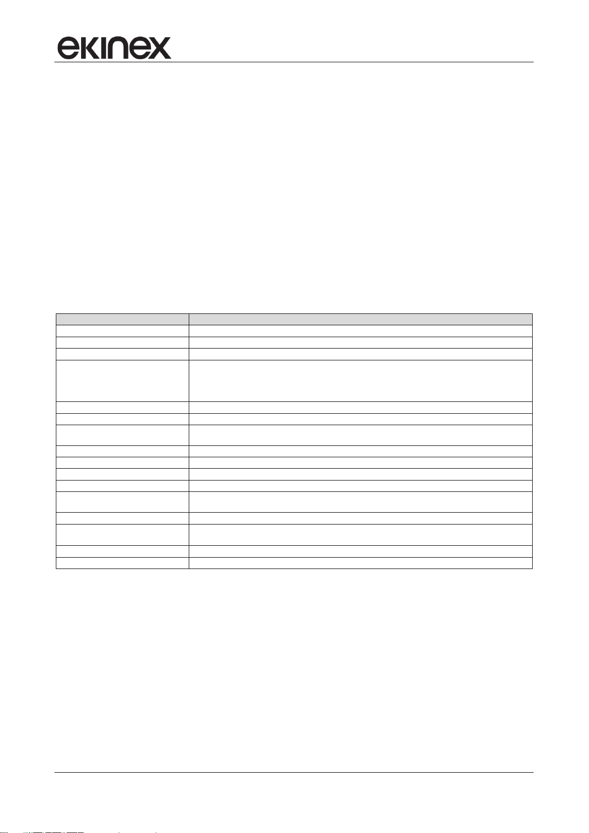
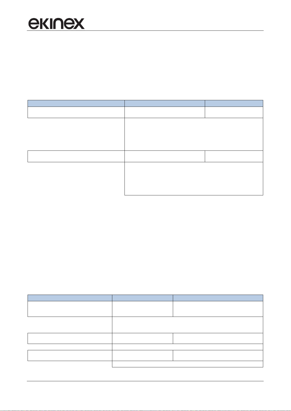
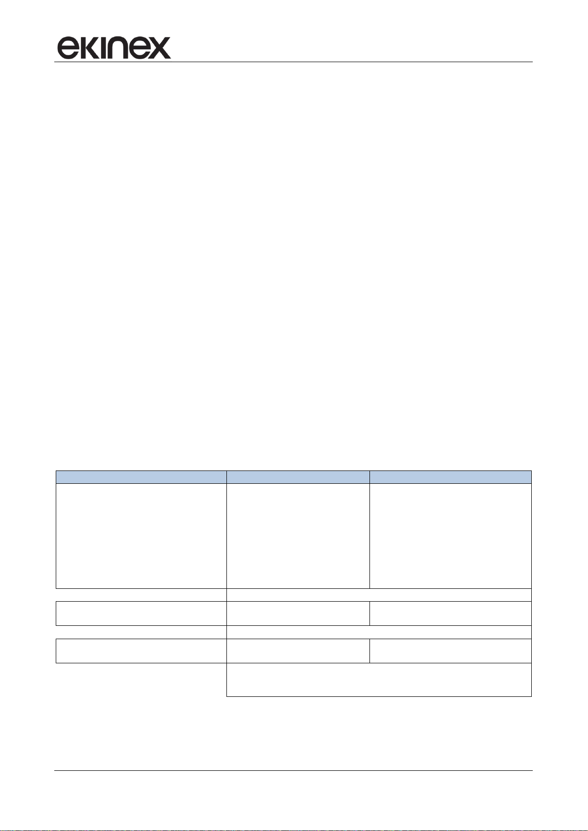
Feature
Valore
Device
KNX S-mode bus device
Communication
according KNX TP1 standard
Use
dry internal rooms
Environmental conditions
• Operating temperature: - 5 ... + 45°C
• Storage temperature: - 25 ... + 55°C
• Transport temperature: - 25 ... + 70°C
• Relative hunidity: 95% not condensating
Power supply
SELV 30 Vdc from bus KNX (auxiliary power supply not necessary)
Current consumption from bus
< 13 mA
Elementi di comando
2-fold pushbutton for direct access to 4 funzioni indipendenti mediante pressione breve (< 5 s)
e indiretto ad altre funzioni mediante pressione prolungata (> 5 s)
Programming elements
1 pushbutton and 1 LED (red) on the front side
Display elements
1 backlighted LC-display, 8 LED (4 for each rocker)
Temperature sensor
1 integrated NTC-type
R.H. sensor
1 integrated
Accessories
2 square (40x40 mm) rockers and a square frame of the flank or form series (to be ordered
separately) - ‘NF (No Frame versions) do not require any frame
Installation
On round or square wall-mounting box with disatnce between fixing holes of 60 mm
Connection
• bus: black/red KNX terminal block
• inputs: screw terminal blocks
Protection degree
IP20
Dimensions (WxHxD)
82 x 75 x 35 mm
KNX room temperature controller EK-EQ2-TP
• temperature displaying (measured, setpoint, perceived and outdoor values in °C or °F), relative
humidity (measured and setpoint values in %) and CO
-concentration (in ‰, received from bus),
2
alarms and errors (with alphanumeric codification);
• signaling opening windows;
• calculation of psychrometric values (dew-point temperature and perceived temperature) with
possibility of sending the values on the bus;
• limitation of the surface temperature for floor heating radiant panels;
• anticondensation protection for floor and ceiling cooling radiant panels;
• antistratification function;
• delayed fan start (“hot-start” function) time-scheduled or depending on the conveying fluid
temperature measured at the coil battery;
• sending on the bus of the condition internal or external from the area of comfort (configurable).
1.3 Technical data
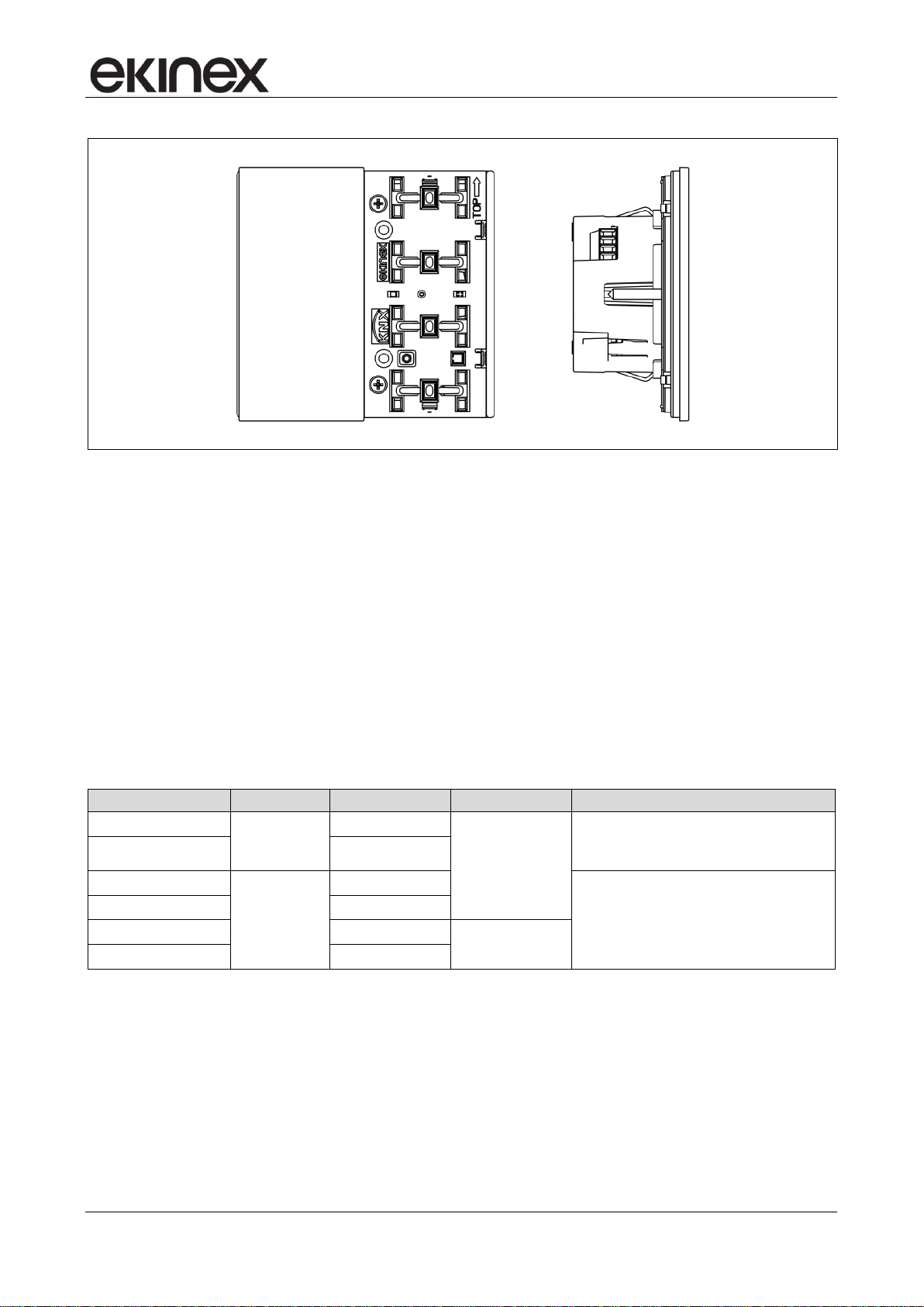
1.4 Design
The device is realised for wall-mounting on round or square wall box with distance between fixing holes of 60
mm. The programming pushbutton and the programming led are on the front side under the rockers. On the
rear side of the housing there is the 4-pole terminal block for the connection of the 2 inputs and the terminal
block for the connection of the bus.
Release 3.00 - Updating: 27/06/2017 Application Manual
© SBS S.p.A. - All rights reserved Page 7
Application manual
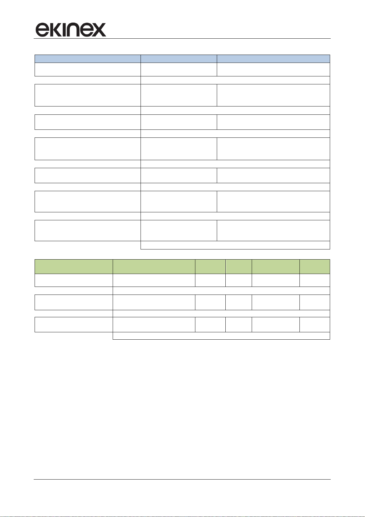
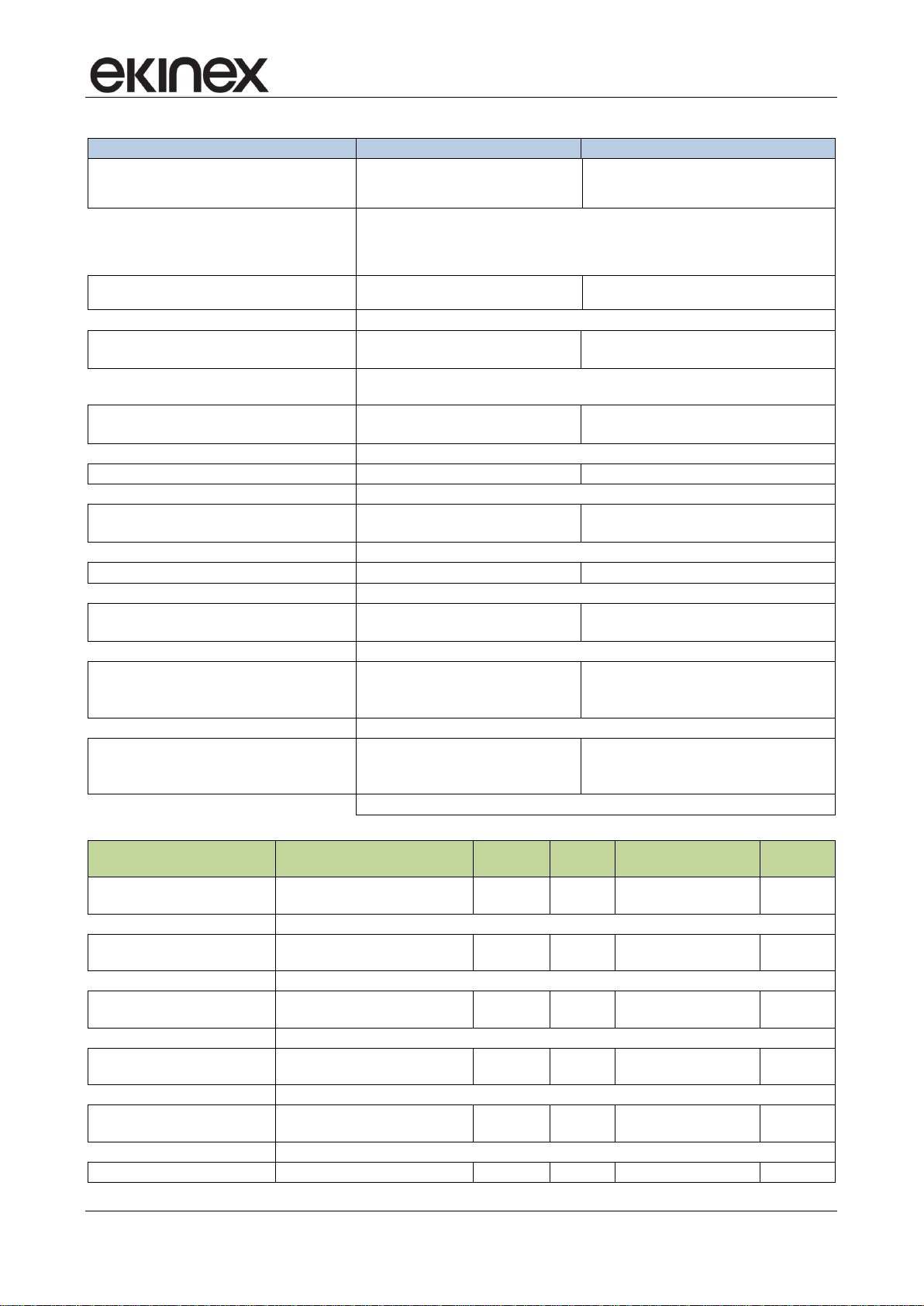
Code
Version
LED colours
Device housing
Accessories
EK-EQ2-TP
with frame
blue / green
black plastic
set rockers EK-TSQ-G...-EP2 and square
frame of form (EK-FOQ-...)
or flank (EK-FLQ-...) series
EK-EQ2-TP-RW
white / red
EK-EQ2-TP-BG-NF
‘NF (without
frame)
blue / green
set rockers EK-TSQ-G...-EP2
EK-EQ2-TP-RW-NF
white / red
EK-EQ2-TP-BG-NFW
blue / green
white plastic
EK-EQ2-TP-RW-NFW
white / red
KNX room temperature controller EK-EQ2-TP
Device: front and side sights
1.5 Delivery
The delivery includes a device, the terminal block for the connection of the bus, the screws (2 pairs) and the
metallic support for mounting on the wall box. The packaging inlcludes also the device instructions.
1.6 Accessories
The device is completed with a set of two square 40x40 mm rockers and a square frame of the form (EKFOQ-...) or flank (EK-FLQ-...) series that have to be ordered separately. The ‘NF (No Frame) version does
not require any frame (see also the following table). Temperature sensors and other devices to be connected
to the inputs must be ordered separately.
Accessories of the device: set of rockers and frames
1.7 Marks and certification
The KNX mark on the ekinex device ensures interoperability with the KNX devices of SBS and other
manufacturers installed on the same system bus system. The compliance with the applicable European
directives is indicated by the presence of the CE mark.
Release 3.00 - Updating: 27/06/2017 Application Manual
© SBS S.p.A. - All rights reserved Page 8

Application manual
KNX room temperature controller EK-EQ2-TP
2 Installation
The device has degree of protection IP20, and is therefore suitable for use in dry interior rooms. The
installation of the device requires the following steps:
a) fix the metallic support with the screws supplied on a wall box with distance between fixing ho les of
60 mm. It is recommended to install the device at a height of 150 cm;
b) if required, snap a square frame of the form or flank series, inserting it from the rear of the device;
c) connect the sensors or the contacts required to the 4-poles screw terminal block on the rear of the
device;
d) insert the terminal for the bus (red/black), previously connected to the bus cable, in its slot on the
rear side. At this point it is recommended to carry out the commissioning of the device or at least the
download of the physical address;
e) install the device on the metallic support through the spring system, tightening then the two screws
f) requires also to tighten the screws included in the delivery. For mounting the device follow also the
indication TOP (arrow tip pointing up) on the rear side of the device;.
g) snap the two rockers onto the device for the operation of the room temperature controller.
The device can only be mounted on a round or square wall flush mounting box with 60 mm distance between
fixing holes. If necessary, the metallic support for mounting on the wall box can also be ordered separately.
2.1 Connection
For the operation the device has to be connected to the bus line and addressed, configured and
commissioned with ETS (Engineering Tool Software). The connection of one or two sensors to the inputs is
optional and must be defined by the planner of the bus system.
2.1.1 Connection of the bus line
The connection of the KNX bus line is made with the terminal block (red/black) included in delivery and
inserted into the slot of the housing.
Characteristics of the KNX terminal block
• spring clamping of conductors
• 4 seats for conductors for each polarity
• terminal suitable for KNX bus cable with single-wire conductors and diameter between 0.6 and 0.8
mm
• recommended wire stripping approx. 5 mm
• color codification: red = + (positive) bus conductor, black = − (negative) bus conductor
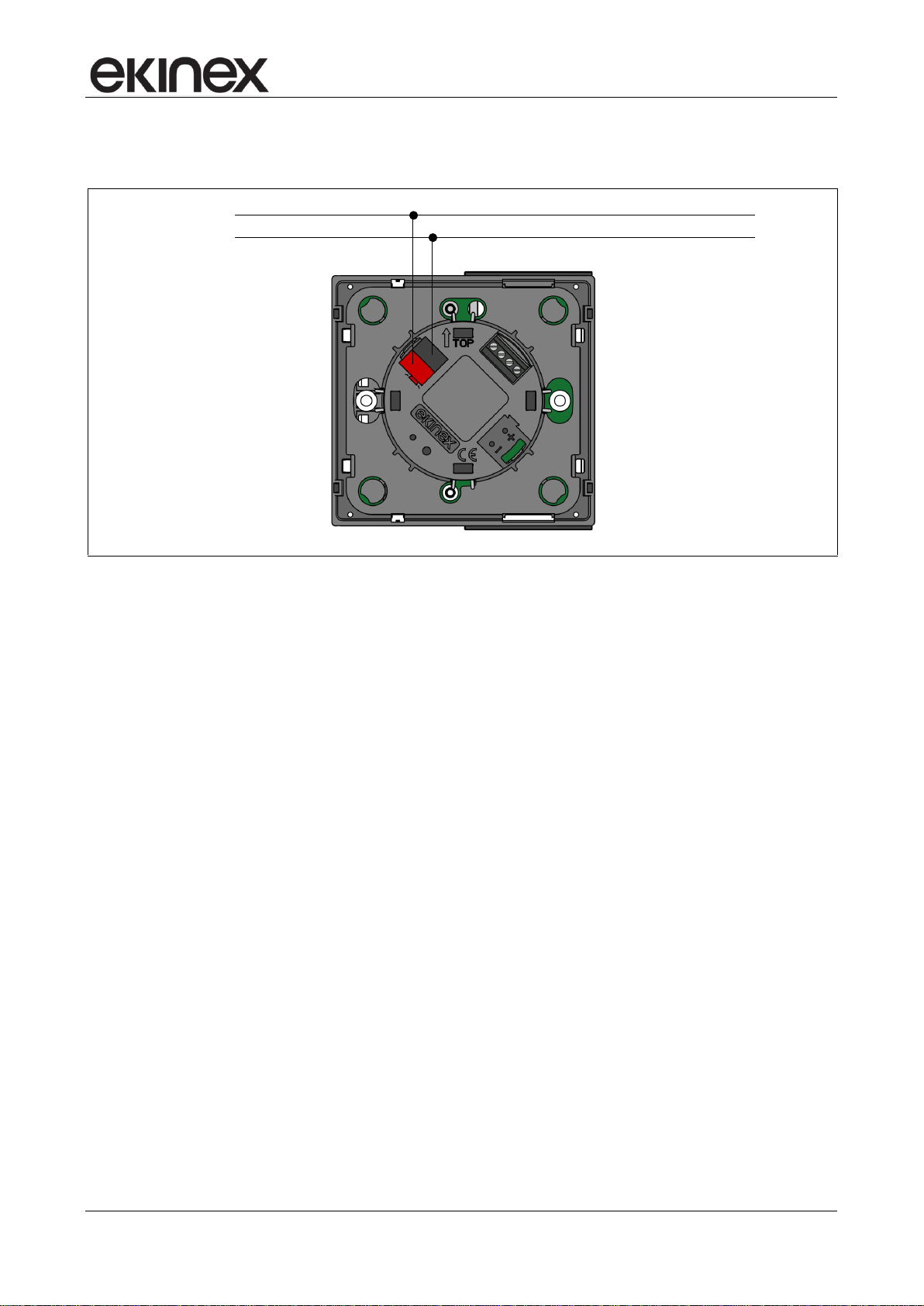
2.1.2 Connection of the inputs
The connection of the inputs is made with the screw terminals located at the rear side of the device. The
maximum cable length is 10 m. For the connection use a cable of max section 1,5 mm². The connection
cable must have sufficient length to allow the extraction of the device from the wall-mounting box.
Characteristics of the terminal blocks for the inputs
• screw clamping of conductors
• maximum cross section of conductor 1 mm² (multiwire)
• recommended wire stripping approx. 5 mm
Release 3.00 - Updating: 27/06/2017 Application Manual
© SBS S.p.A. - All rights reserved Page 9
Application manual
KNX
bus
+
–
KNX room temperature controller EK-EQ2-TP
• torque max 0.2 Nm
Connection of the device of the bus line
Release 3.00 - Updating: 27/06/2017 Application Manual
© SBS S.p.A. - All rights reserved Page 10
Application manual
KNX room temperature controller EK-EQ2-TP
3 Configuration and commissioning
The configuration and commissioning are carried out with the ETS (Engineering Tool Software) tool and the
ekinex® application program provided free of charge by SBS; you do not need any additional software neither
plug-in tool. For further information on ETS see also www.knx.org.
3.1 Configuration
The device functionality is defined by the settings done via software. The configuration requires necessarily
ETS4 (or later releases) and the ekinex® APEKEQ2TP##.knxprod (## = release) application program that
can be downloaded from the website www.ekinex.com. The application program allows the configuration of
all working parameters for the device. The device-specific application program has to be loaded into ETS or,
as alternative, the whole ekinex® product database can be loaded; at this point, all the instances of the
selected device type can be added to the project.
Application program for ETS APEKEQ2TP##.knxprod (## = version)
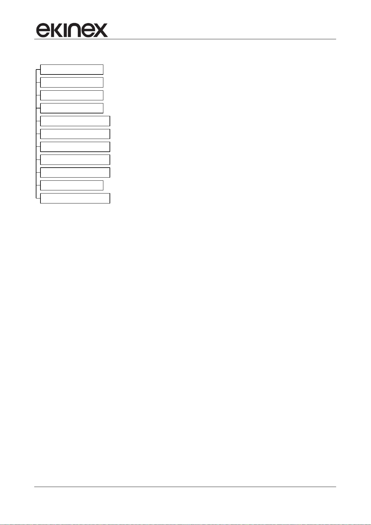
3.1.1 Tree structure of the application program
At its opening, the tree structure of the program includes the following main items:
Release 3.00 - Updating: 27/06/2017 Application Manual
© SBS S.p.A. - All rights reserved Page 11
Application manual
About EK-EQ2-TP
General
Internal sensors
Inputs
External sensors (from bus)
LCD display
Led
Temperature control
Relative humidity control
Comfort
Energy saving
KNX room temperature controller EK-EQ2-TP
Other items may appear depending on the choices done for the parameters in the several folders.
3.1.2 Languages of the application program
The application program is available in four languages: English, Italian, German and French. The language
displayed can be changed in ETS choosing "Settings / Presentation language".
Release 3.00 - Updating: 27/06/2017 Application Manual
© SBS S.p.A. - All rights reserved Page 12

Application manual
For commissioning the device the following activities are required:
• make the electrical connections;
• turn on the bus power supply;
• switch the device operation to the programming mode by pressing the
programming pushbutton located on the front side of the housing. In this
mode of operation, the programming LED is turned on;
• download into the device the physical address and the configuration with the
ETS
®
program.
When downloading the application program the display shows "PrOg" and the
flashing symbol of the clock. At the end of the download the operation of the device
automatically returns to normal mode; in this mode the programming LED is turned
off. Now the bus device is programmed and ready for use.
1
2
KNX room temperature controller EK-EQ2-TP
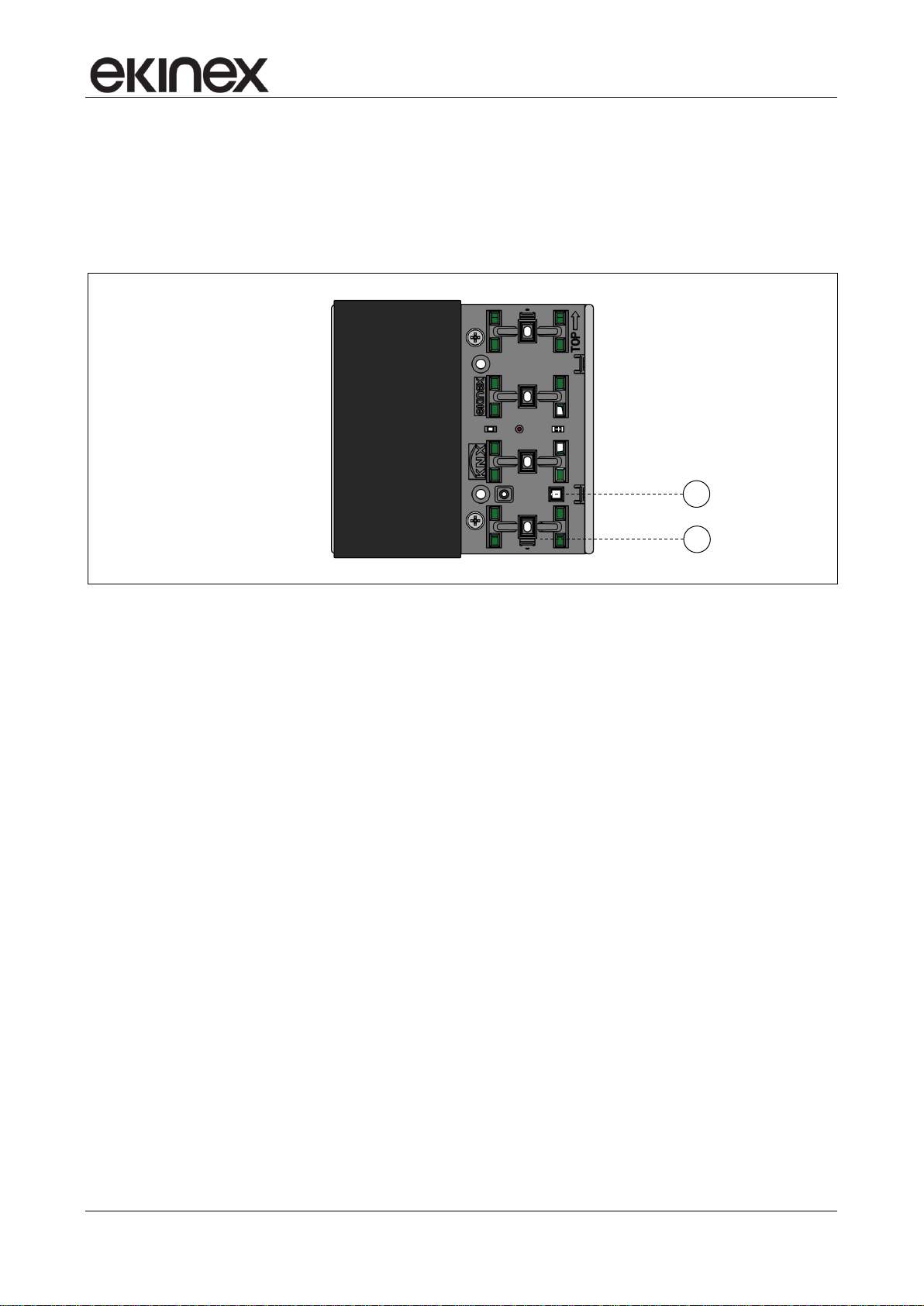
3.2 Commissioning
For the commissioning the device is provided on the front side (in the area usually occupied by the rockers)
with:
• a red LED (1) for indication of the active operating mode (LED on = programming, LED off = normal
operation);
• a pushbutton (2) for switching between the normal and programming operating mode.
Device programming: led (1) and pushbutton (2)
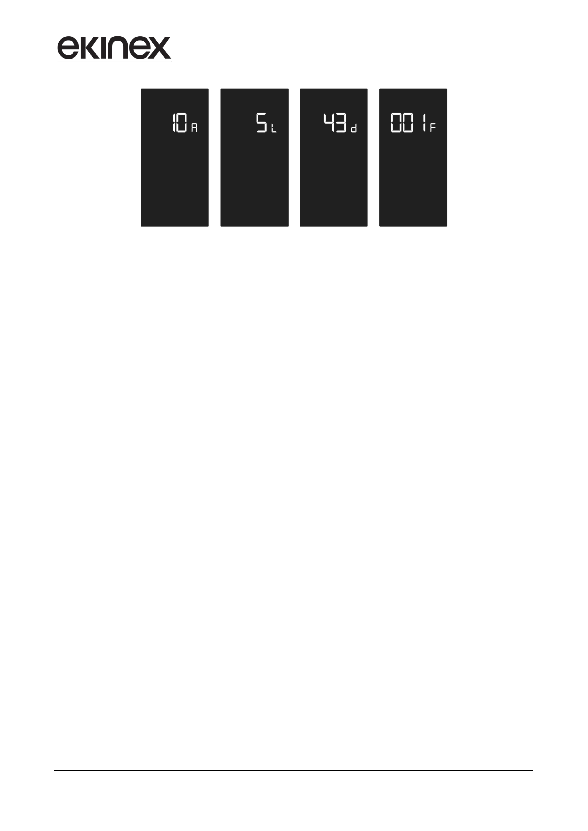
3.2.1 Displaying physical address and firmware release
Once the first addressing is done, you can check anytime the physical address and the firmware release
directly on the device display. In order to display it, press for more than 3 seconds the – (minus) symbol on
the lower rocker and the symbol on the upper rocker. All segments of the display are turned off;
displaying a physical address only the 3 large digits and the small one are active. The information displayed
in sequence are: the area number (A), the line number (L), the device number (d) and the firmware release
(F). To scroll through the three elements of the physical address press + or –.
Release 3.00 - Updating: 27/06/2017 Application Manual
© SBS S.p.A. - All rights reserved Page 13
Application manual
KNX room temperature controller EK-EQ2-TP
Example of displaying the physical address 10.5.43 (device nr. 43, installed on the line 5 of the area 10) and the firmware release 001
To exit from the physical address displaying press shortly (< 3 seconds) the symbol on the lower
rocker. If you elapse of time interval set in parameter “Time to exit change without saving” without pressing
any rocker, the device returns automatically to the previously displayed information.
Release 3.00 - Updating: 27/06/2017 Application Manual
© SBS S.p.A. - All rights reserved Page 14
Application manual
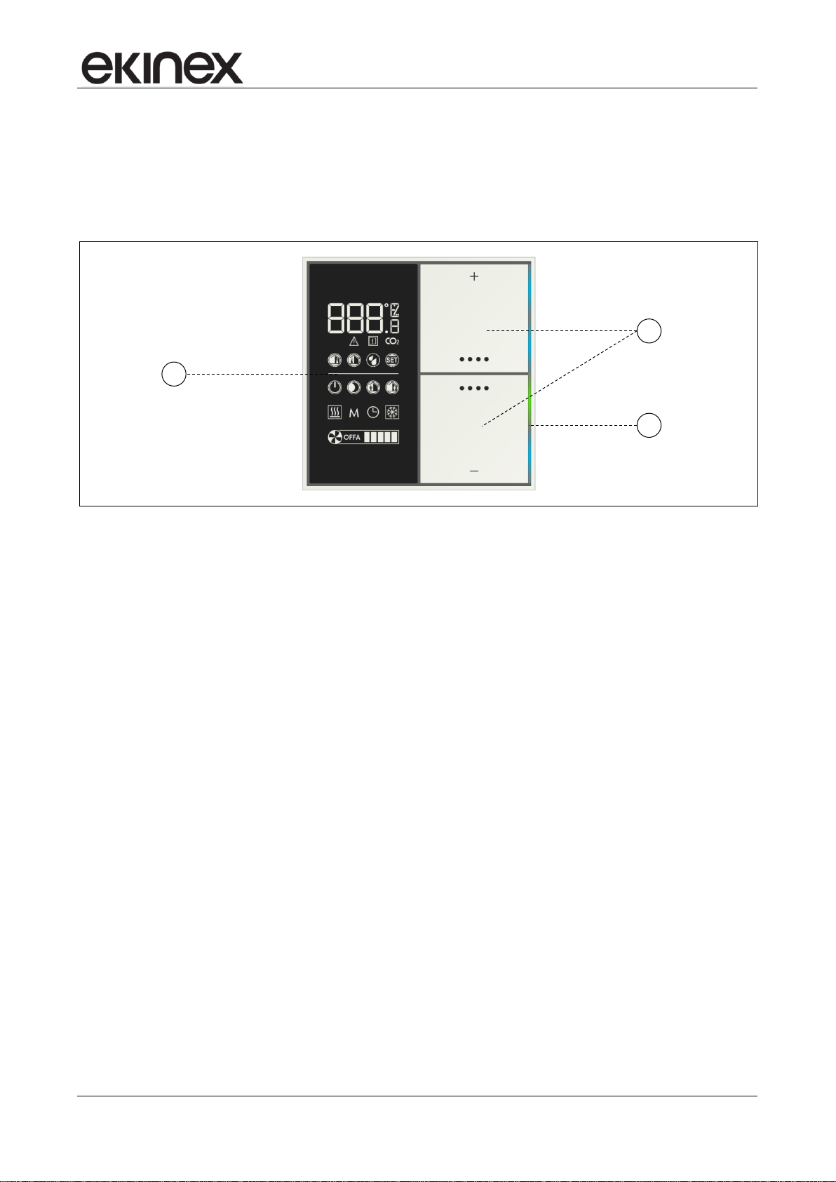
2
1
3
KNX room temperature controller EK-EQ2-TP
4 User interface
The user interface of the room temperature controller includes a LC-display, a pushbutton with two rockers
and a series of freely programmable LEDs (4 for each rocker). The colour of the LEDs depend on the device
version.
User interface: LC-display (1), rockers (2), LEDs (3) with lightguide
The symbols on the rockers recall the function carried out:
+ temperature (or other parameters) increase;
‒ temperature (or other parameters) decrease;
information sequence, operating mode change, ventilation control, seasonal change-over.
Through a combined pressure of various symbols other functions can be carried out.
4.1 LCD-display
The device is provided with a LC-display (1) with adjustable backlight that occupies a vertical area of approx.
40 x 80 mm (WxH) in the left half of the device.
4.1.1 Information displaying
Depending on the configuration done with ETS, the connections and the availability of information (local or
received from the bus), the series of symbols allow to display:
room actual temperature (it may be the temperature calculated using a weighted average of two
values);
outdoor temperature, preceded by a ‒ (minus) sign in case of outdoor temperature below 0°C;
relative humidity (in %, without decimals);
perceived temperature (estimated with the measured values of temperature and relative humidity);
temperature setpoint (for the actual operating mode);
concentration of CO2 (in ‰);
alarm and error condition (A01, A02… E01, E02…);
window opening;
Release 3.00 - Updating: 27/06/2017 Application Manual
© SBS S.p.A. - All rights reserved Page 15
Application manual
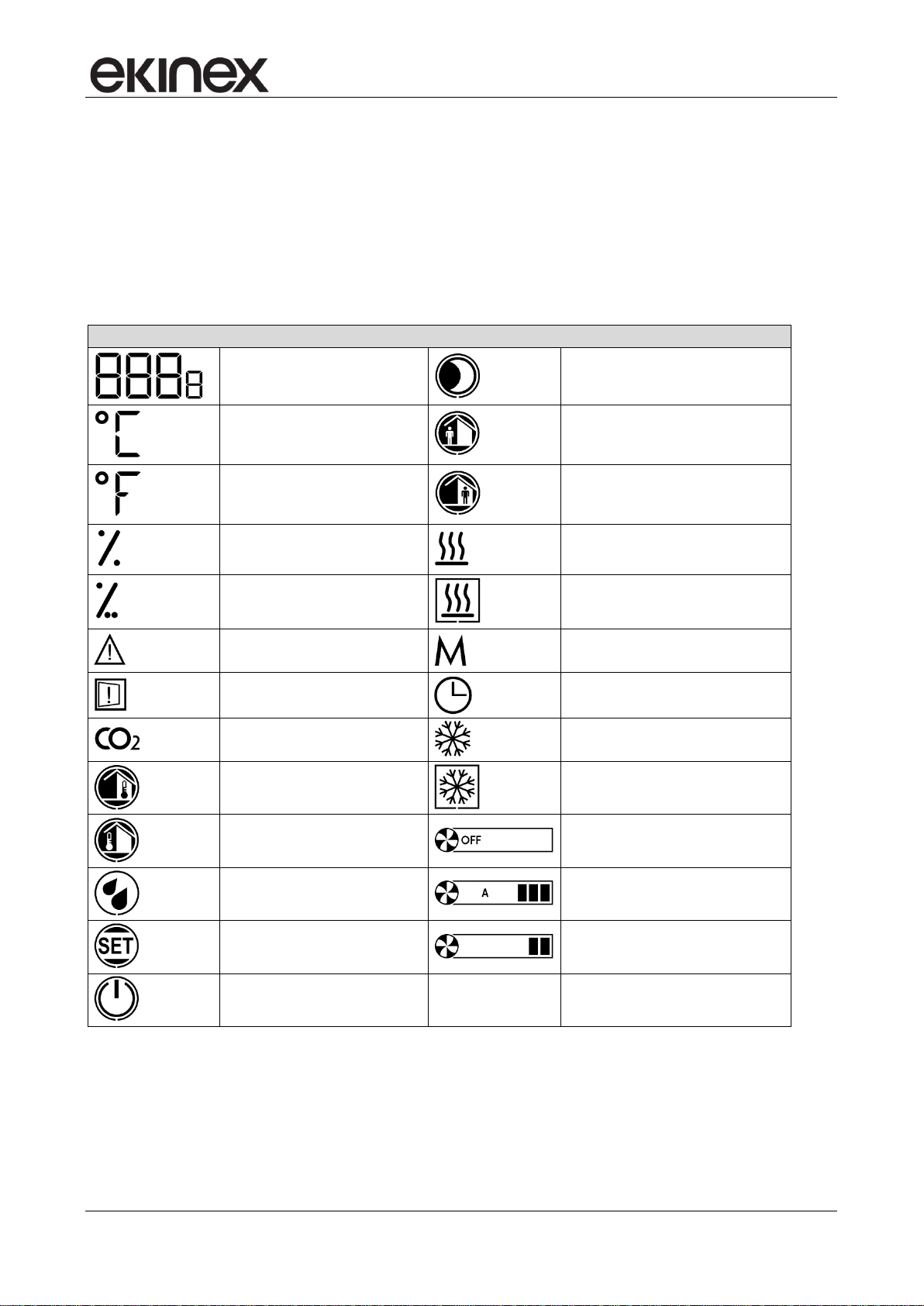
Display symbols
Digits (for numeric values display)
Economy operating mode (night)
Celsius degrees
Standby operating mode
Fahrenheit degrees
Comfort operating mode
Percentage (relative humidity)
Heating mode active (device not calling
or setpoint reached)
Per mille (only for CO2
concentration)
Heating mode active (device calling or
setpoint not reached)
Alarm
Manual operation (M)
Window opening
Slave (operation subordinated to a
supervising KNX device)
Carbon-dioxide (CO2)
Cooling mode active (device not calling
or setpoint reached)
Indoor temperature
Cooling mode active (device calling or
setpoint not reached)
Outdoor temperature
OFF (fan-coil switched off)
Relative humidity
Automatic fan-coil operation (example:
speed 3)
SET
Manual fan-coil operation (example:
speed 2)
Building protection operating mode
(off)
KNX room temperature controller EK-EQ2-TP
operating mode (comfort / standby / economy / building protection);
seasonal mode (heating / cooling);
device status calling / not calling (or setpoint reached / not reached);
operation in manual mode (M);
operation as slave device (clock);
fan status (1-2-3-automatic-off), when present;
device physical address assigned by ETS.
4.1.2 Segment test
The segment test allows you to check at any time the proper functionality of the display. In order to do the
test, press simultaneously + (plus) on the upper rocker and the symbol on the lower rocker for more
Release 3.00 - Updating: 27/06/2017 Application Manual
© SBS S.p.A. - All rights reserved Page 16
Symbols that can be activated on the LC-display
Application manual
Rockers use
Upper rocker
Lower rocker
Functions for room temperature
controlling
+ and
and ‒
KNX room temperature controller EK-EQ2-TP
than 3 seconds. All symbols are activated simultaneously; then all the symbols are turned off. In the test
phase keep available the instructions or the user guide.
If you elapse the time set in the parameter "Time to exit change without saving" (General folder) without
pressing a button, the device will return to the previous situation.
4.1.3 Backlight
The backlight intensity of the LC-display is adjustable. The first setting is done when configuring the device
using ETS, but the intensity can be changed later at any time.
To access the change press simultaneously + (plus) and (bothon the upper rocker) for more than 3
seconds. All symbols are turned off except the digits and the percentage symbol. The actual value (as a
percentage) of backlight intensity is displayed. At each pressing of + or – the intensity is increased or
decreased by 5%. To confirm the selected intensity press shortly (< 3 seconds) the symbol either on
the upper rocker. Three rapid flashes of the digits indicate that the new value was saved. If you elapse of
time interval set in the "Time to exit change without saving " (General folder) without pressing any rocker, the
device returns to the previous situation.
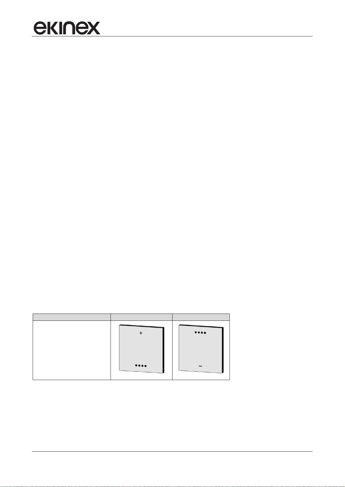
4.2 Rockers
The pushbutton with two rockers integrated in the device controls the functions of the thermostat. The set of
two rockers has to be ordered separately; the symbols on the rockers of the set are pre-defined and cannot
be changed. The areas marked by the symbols + (plus) and – (minus) allow you to change a setting (e.g. the
temperature setpoint), while those marked by the symbol ●●●● allow you to display a sequence of
information, to change the operating mode, to control the ventilation, to do the seasonal change-over
(heating to cooling and vice versa) or to confirm a setting change.
The part number of the set EK-TSQ-Gxx-EP2 must be completed with the part (xx) that identifies the
material, color and finishing; for the exact code please refer also to the latest edition of the ekinex product
catalog or the website www.ekinex.com.
Release 3.00 - Updating: 27/06/2017 Application Manual
© SBS S.p.A. - All rights reserved Page 17
Application manual
2
1
KNX room temperature controller EK-EQ2-TP
5 Sensors
The room temperature controller is equipped with three sensors:
• temperature (1);
• relative humidity (2).
Position of the sensors: temperature (1), relative humidity (2).
The temperature sensor (not to be seen in the drawing) is located under the plastic half-shell for the rockers’ mounting.
5.1 Temperature sensor
The integrated temperature sensor allows the measureming of the room temperature in the range from 0 °C
to +40 °C with a resolution of 0.1 °C. To keep into account significant environmental interferences such as
the proximity to heatsources, the installation on an outer wall, the chimney effect due to rising warm air
through the corrugated tube connected to the wall-mounting box, the measured value can be corrected by
means of a offset of ± 5 °C or, preferably, can be used a weighted average between two values of
temperature chosen from the following ones: value measured by the integrated sensor, value measured by a
temperature sensor connected to one of the inputs of the device, value received via bus from another KNX
device (such as ekinex pushbuttons).
5.2 Relative humidity sensor
The integrated relative humidity sensor allows the measuring of the relative humidity value in the room. The
measured value allows you to make an advanced room thermoregulation and enlarge the opportunities for a
safe operation of certain types of terminal equipments used for cooling. The measured value can also be
sent on the bus via the 114 (1 byte) and the 115 (2 bytes) Communication Objects.By means of a calculation
performed by the thermostat, on the bus can also be sent psychrometric values obtained from the combined
measurement of temperature and humidity, such as the dew-point temperature, as well as the index of
perceived temperature (only in summer mode).
Release 3.00 - Updating: 27/06/2017 Application Manual
© SBS S.p.A. - All rights reserved Page 18
Application manual
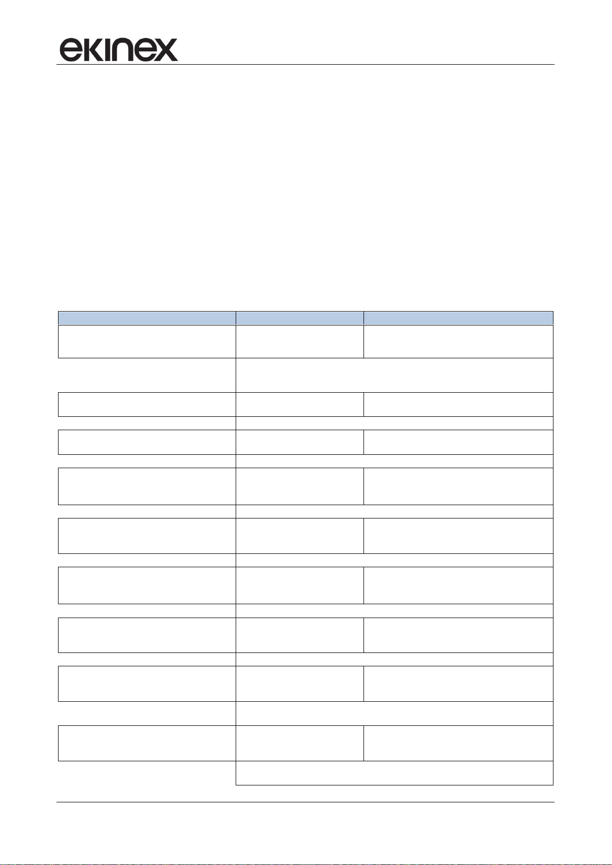
Data
Coming from
Description
Room temperature
Internal sensor
Analogic value for thermoregulation functions
Room relative humidity
Analogic value for thermoregulation functions
Window state (open/close)
Input 1 or 2 (device
terminals)
configurated
[DI] window contact sensor
Card holder state (badge in/out)
[DI] card holder contact sensor
Presence of condensation
[DI] anticondensation sensor
Conveying fluid temperature at the exchange coil
[AI] coil battery temperaure sensor
Room temperature (for weighted average value)
[AI] room temperature sensor
Room temperature (other measurement height)
[AI] antistratification temperature sensor
Floor surface temperature
[AI] floor surface temperature sensor
Outdoor temperature
[AI] outdoor temperature sensor
Further temperature value
[AI] generic (NTC) temperature sensor
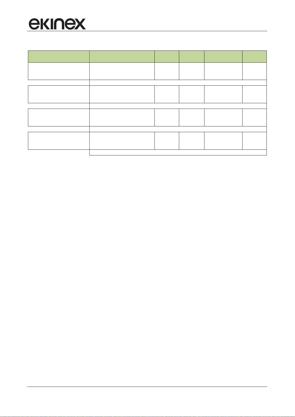
Room temperature
KNX bus (through
communication
objects)
Object 34 (2 bytes)
Room relative humidity
Objects 35 (2 bytes) and 36 (1 byte)
Antistratification temperature
Object 37 (2 bytes)
Outdoor temperature
Object 38 (2 bytes)
CO
2
concentration (air quality)
Object 39 (2 bytes)
Conveying fluid temperature at the exchange coil
Object 40 (2 bytes)
Floor surface temperature
Object 41 (2 bytes)
Conveying fluid flow temperature
Object 42 (2 bytes)
Presence of condensation
Object 46 (1 bit)
Window state (open/close)
Objects 43 and 44 (1 bit)
Presence of people in the room
Objects 32 and 33 (1 bit)
Card holder state (badge in/out)
Object 45 (1 bit)
KNX room temperature controller EK-EQ2-TP
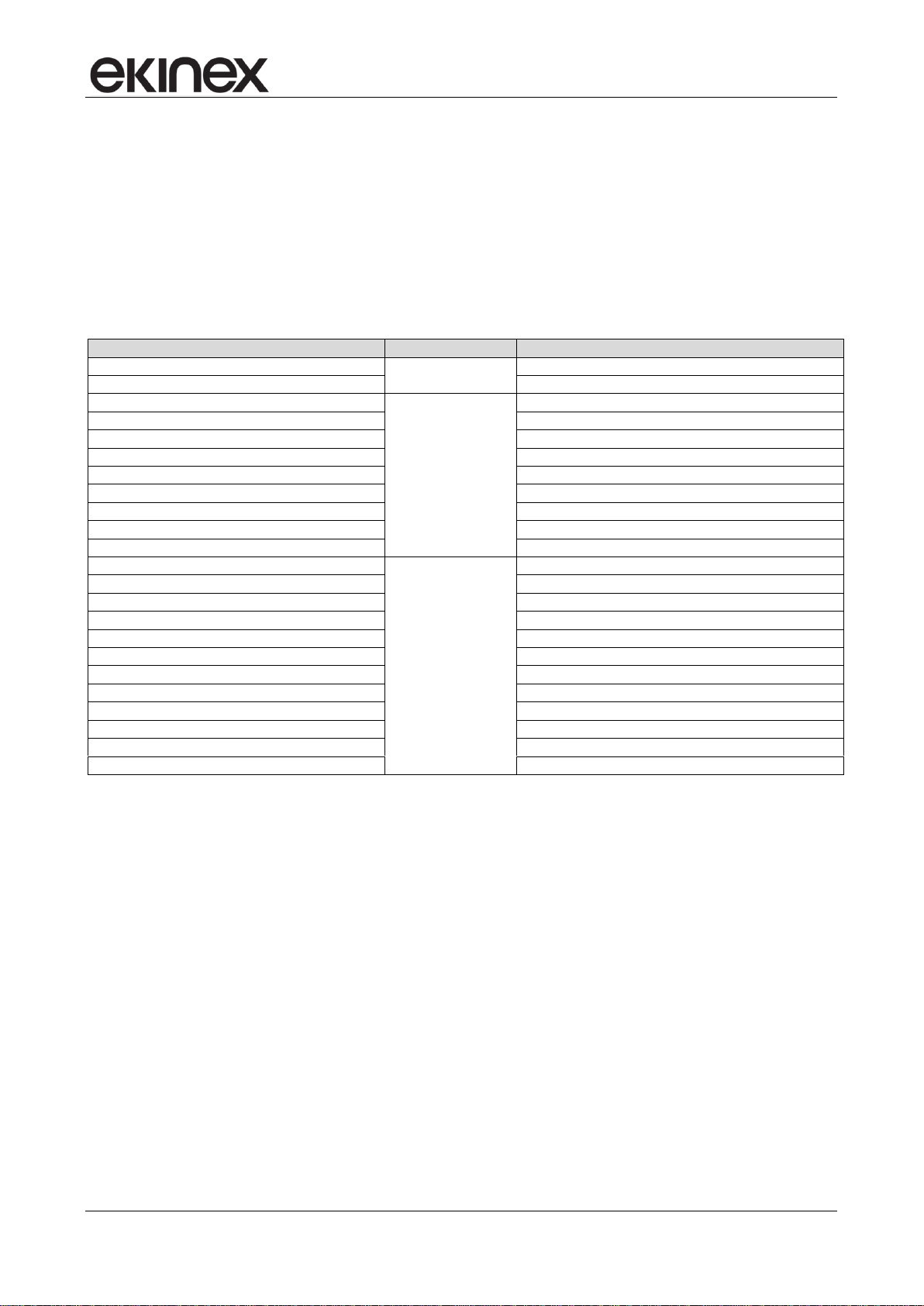
6 Input variables
The data that the device usesin its control algorithms and /or to be displayed may come from:
• the internal sensors;
• sensors or digital signals connected to the two physical inputs of the device;
• the KNX bus through standard Communication Objects.
The processed data can also be transmitted on the KNX bus as Communication Objects.The classification of
the input variables is shown in the following table.
The device does not have outputs for direct switching or control of heating/cooling terminals or for status or
values signalling. The output variables include exclusively communication objects that are sent on the bus,
received and processed by KNX actuators (general-purpose or dedicated to HVAC applications).
Release 3.00 - Updating: 27/06/2017 Application Manual
© SBS S.p.A. - All rights reserved Page 19
Input variables from internal sensors, physical inputs and standard communication objects.
Application manual
About EK-EQ2-TP
General
Temperature sensor
Internal sensors
Inputs
External sensors ( from bus)
LCD display
Led
Settings
Heating
Temperature control
Relative humidity control
Comfort
Windows contacts
Presence sensors
Card holder
Energy saving
KNX room temperature controller EK-EQ2-TP
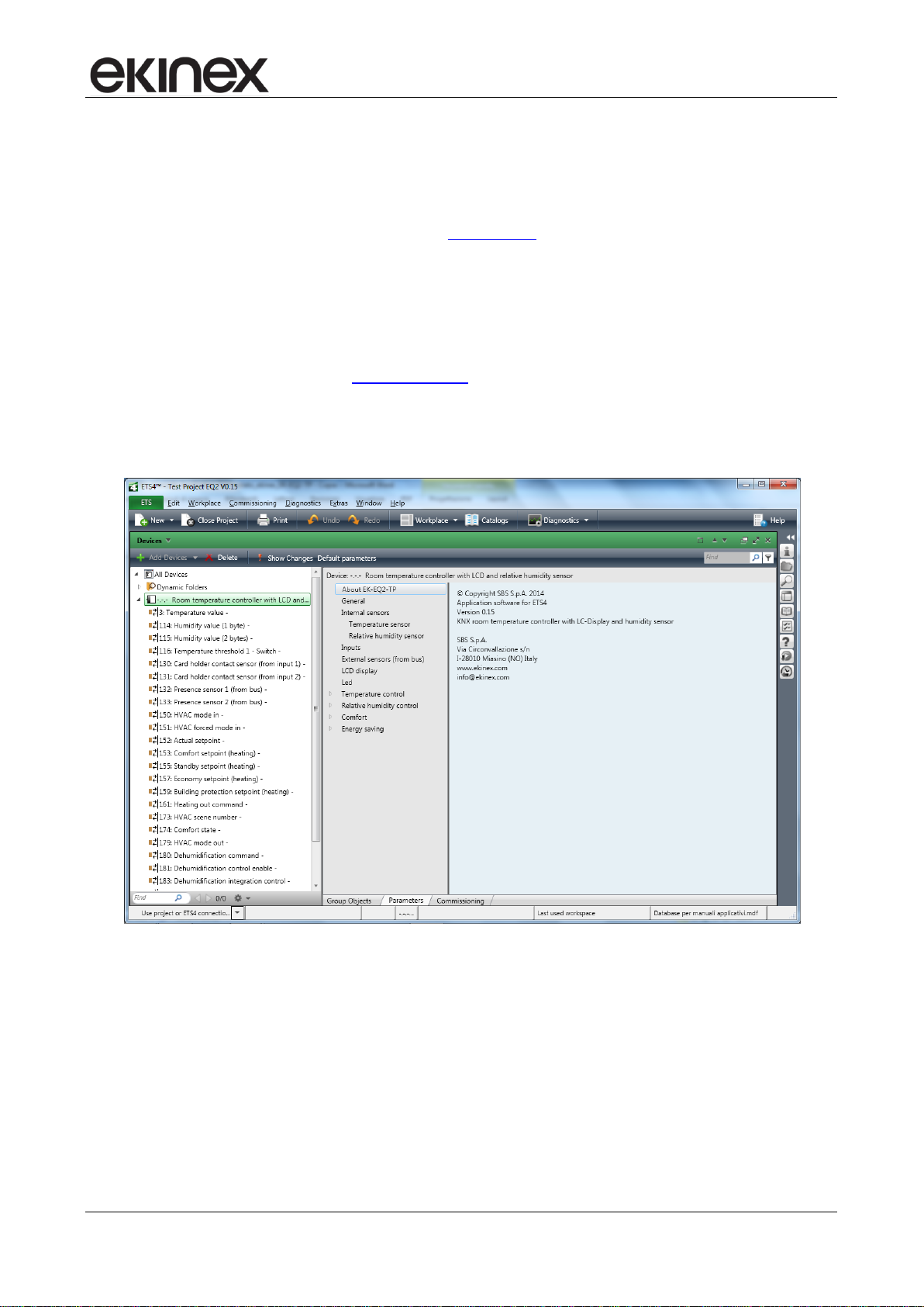
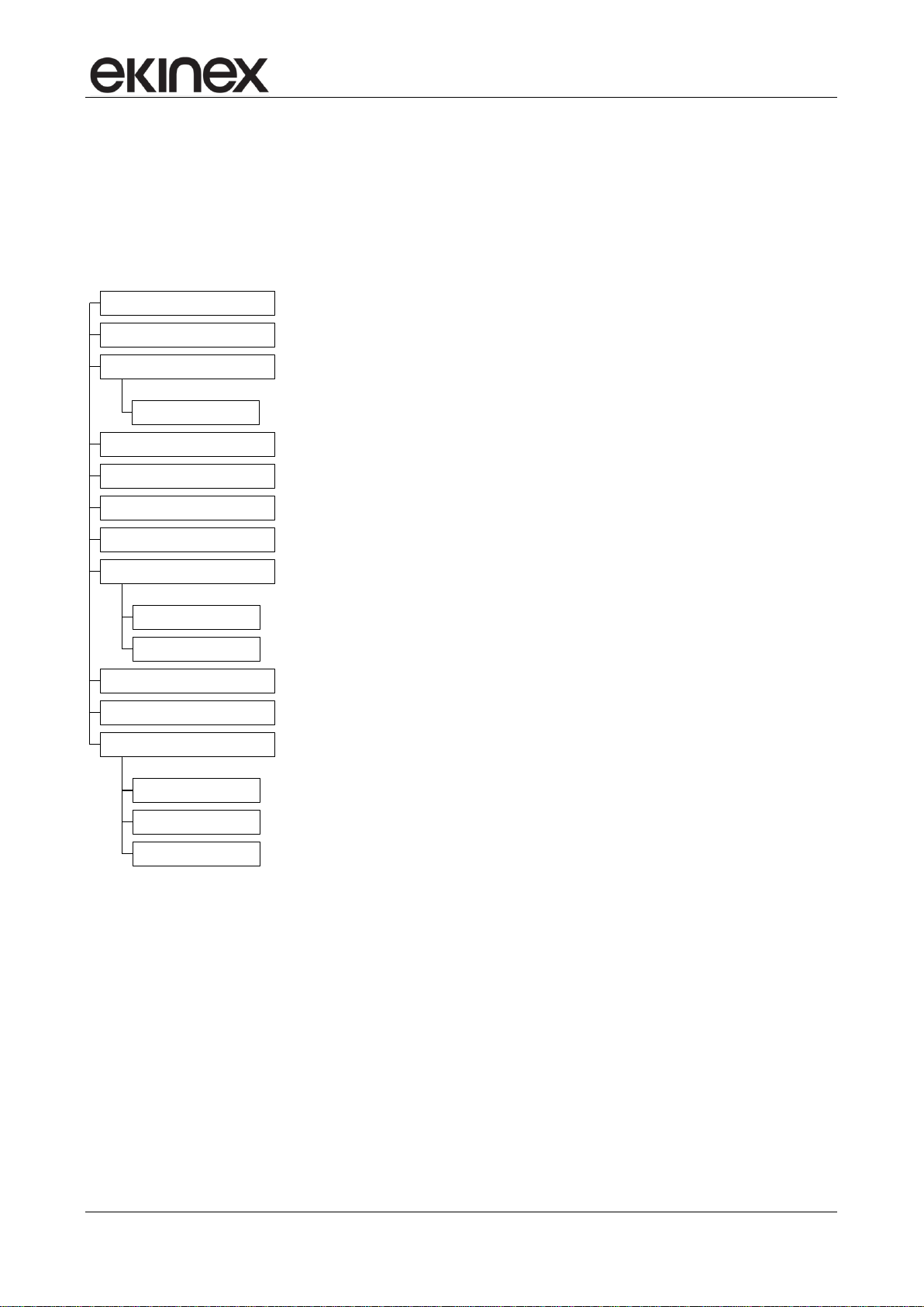
7 Application program for ETS
In the following chapters there is the list of folder, parameters and communication objects of the application
program. Some specific functions of the thermostat are described in more detail in the dedicated paragraphs.
The tree structure of the application program as imported into ETS (or by pressing the "Default Parameters"
button of ETS) is the following:
Other folders may appear depending on the choices done for the parameters of the folders represented in
the main tree structure.
7.1 About EK-EQ2-TP
The folder About EK-EQ2-TP is for information purposes only and does not contain parameters to be set.
The information given is:
© Copyright SBS S.p.A. 2016
Application software for ETS4
Version 2.00 (or later)
KNX room temperature controller with LC-display and humidity sensor
SBS S.p.A.
Via Circonvallazione s/n
I-28010 Miasino (NO) Italy
Release 3.00 - Updating: 27/06/2017 Application Manual
© SBS S.p.A. - All rights reserved Page 20

Application manual
Parameter name
Conditions
Values
Device operation as
stand-alone
stand-alone/chrono
slave
If configured as stand-alone/chrono the operating mode can be selected
manually on the device; in that way, the commands received via bus are
ignored. If changing the operating mode the watch symbol is selected, the
commands received via bus are accepted again.
If configured as slave, the room temperature controller receives from a KNX
device (acting as supervisor) HVAC modes, setpont values, etc.
Temperature displayed unit
Celsius
Fahrenheit
Default displayed information
actual temperature
temperature setpoint
The actual temperature is the value by which the device performs the
temperature regulation. It may be the value measured from a single sensor
(internal, from the bus or from an input) or the weighted average of the
temperatures measured by a main sensor and an additional sensor.
The displayed setpoint temperature is that of the operating mode currently
set on the room temperature controller (deduced from the symbol on).
Time to return to default display information
5 s
[other values in the range 10
s … 1 min]
Time interval after which the display automatically switches between the
manually recalled information to the default information.
Button function level
end user
system integrator
This parameter allows you to partially inhibit the functions that can be
recalled using the rockers.
Time to exit change without saving
8 s
[other values in the range 2
s … 12 s]
Time interval without further pressing of the rockers at the end of which the
device exits the procedure without saving the current changes.
KNX room temperature controller EK-EQ2-TP
www.ekinex.com
info@ekinex.com
7.1.1 General
The General folder includes the following parameters:
Device operation as
Temperature displayed unit
Default displayed information
Time to return to default display information
Button function level
Time to exit change without saving
Delay after bus voltage recovery
The folder has no secondary folders.
7.1.2 Parameters
Release 3.00 - Updating: 27/06/2017 Application Manual
© SBS S.p.A. - All rights reserved Page 21

Application manual
Parameter name
Conditions
Values
Delay after bus voltage recovery
00:00:04.000 hh:mm:ss:fff
[range 00:00:04.000 …
00:10:55.350]
Time interval after which the transmission of the telegrams on the bus starts
after the power supply is restored. The delay affects both the event-driven
transmission and the cyclic transmission of a telegram. Regarding the latter,
the counting of the pause interval for retransmission starts at the end of the
time of initial delay.
The field has format hh:mm:ss:fff (hours : minutes : seconds .milliseconds):
the default value 00:00:04.000 corresponds to 4 seconds.
Logic functions
disabled / enabled
Enable tab to configure logic functions AND, OR, XOR 8-channel (4 inputs
for channel)
KNX room temperature controller EK-EQ2-TP
Information displayed as default
One information between the actual temperature and the temperature setpoint is displayed preferably by the
digits of the display. The device allows you to retrieve and display a series of other information pressing the
●●●● symbol on the upper rocker; after the time set in the parameter "Time to return to default information"
without further pressure of ●●●●, the display automatically returns to the default information.
Functional level of the rockers
The use of the rockers for controlling the room temperature controller can be partially inhibited in the
configuration phase through a filter for the access to the several functions. When using the rockers a
distinction is made between:
first level functions (= short or long pressing of the rockers) for the end user;
second level functions (= combination of rockers); to the first level are added a few functions for a
system integrator or an installer.
The enabled functional level is set through a special parameter.
Release 3.00 - Updating: 27/06/2017 Application Manual
© SBS S.p.A. - All rights reserved Page 22
Application manual
Parameter name
Conditions
Values
Temperature sensor
enabled
disabled
The temperature sensor is enabled as default.
When the sensor is disabled, the corresponding folder disappears from the
main tree structure of the application program; in this case to have available
again the functions for Temperature control you have to enable Room
temperature in the External sensors (from bus) folder or set Input X = [AI]
temperature sensor (X = 1, 2) in the Inputs folder.
Relative humidity sensor
disabled
enabled
The relative humidity sensor is disabled as default.
When the sensor is disabled, the functions that require the value of relative
humidity are available only if you enable Relative humidity in the External
sensors (from bus) folder.
When the sensor is enabled, the corresponding folder appears in the main
tree structure of the application program.
Parameter name
Conditions
Values
Filter type
Temperature sensor = enabled
low
medium
high
Low = average value every 4 measurements
Medium = average value every 16 measurements
High = average value every 64 measurements
Temperature offset
Temperature sensor = enabled
0°C
[range -5°C … +5°C]
Minimum change of value to send [K]
Temperature sensor = enabled
0,5
[range 0 …5]
If the parameter is set to 0 (zero),no value is sent after a change.
KNX room temperature controller EK-EQ2-TP
7.2 Internal sensors
The Internal sensors folder includes the following parameters:
Temperature sensor
Relative humidity sensor
7.2.1 Parameters
7.2.2 Temperature sensor
The Temperature sensor secondary folder appears only if the corresponding sensor is enabled in the folder
Internal sensors and includes the following parameters:
Filter type
Temperature offset
Minimum change of value to send [K]
Cyclic sending interval
Threshold 1
Threshold 2
7.2.2.1 Parameters and communication objects
Release 3.00 - Updating: 27/06/2017 Application Manual
© SBS S.p.A. - All rights reserved Page 23
Application manual
Parameter name
Conditions
Values
Cyclic sending interval
Temperature sensor = enabled
no sending
[other values in the range 30 s … 120 min]
Threshold 1
Temperature sensor = enabled
not active
below
above
Value [°C]
Temperature sensor = enabled,
Threshold 1 = below or above
7
[range 0 … 50]
Threshold 2
Temperature sensor = enabled
not active
below
above
Value [°C]
Temperature sensor = enabled,
Threshold 2 = below or above
45
[range 0 … 50]
Hysteresis
Temperature sensor = enabled,
Threshold 1 and/or Threshold 2
= below or above
0,4 K
[other values between 0,2 K and 3 K]
Cyclic sending interval
Temperature sensor = enabled,
Threshold 1 and/or Threshold 2
= below or above
no sending
[other values in the range 30 s … 120 min]
Object name
Conditions
Dim.
Flags
DPT
Comm.
Obj. No.
Temperature value
Temperature sensor = enabled
2 Bytes
CR-T--
[9.001]
temperature (°C)
3
Temperature threshold1 - Switch
Temperature sensor = enabled,
Threshold 1 = below or above
1 Bit
CR-T--
[1.001] switch
16
Temperature threshold 2- Switch
Temperature sensor = enabled,
Threshold 2 = below or above
1 Bit
CR-T--
[1.001] switch
17
KNX room temperature controller EK-EQ2-TP
Acquisition filter
The acquisition filter calculates an average with a series of measured values before sending on the bus. The
parameter can have the following values:
low = average value every 4 measurements;
medium = average value every 16 measurements;
high = average value every 64 measurements.
Correction of the measured temperature
The sampling of the temperature value occurs every 10 seconds, while the display is updated every minute.
During the configuration with ETS the opportunity is given to correct the measured temperature value within
the offset range of - 5 °C ... + 5 °C (step: 0.1 °C).
Release 3.00 - Updating: 27/06/2017 Application Manual
© SBS S.p.A. - All rights reserved Page 24
Application manual
Parameter name
Conditions
Values
Filter type
Relative humidity sensor =
enabled
low
medium
high
Low = average value every 4 measurements
Medium = average value every 16 measurements
High = average value every 64 measurements
Minimum change of value to send [%]
Relative humidity sensor =
enabled
2
[range 0 …10]
If the parameter is set to 0 (zero), no value is sent after a change.
Cyclic sending interval
Relative humidity sensor =
enabled
no sending
[other values in the range 30 s … 120 min]
Threshold 1
Relative humidity sensor =
enabled
not active
below
above
Value [%]
Relative humidity sensor =
enabled, Threshold 1 = below
or above
65
[range 0 … 100]
Threshold 2
Relative humidity sensor =
enabled
not active
below
above
Value [%]
Relative humidity sensor =
enabled, Threshold 2 = below
or above
65
[range 0 … 100]
Hysteresis [%]
Relative humidity sensor =
enabled, Threshold 1 or
Threshold 2 = below or above
3,0 %
[other values in the range 0,5 … 4,0 %]
The value of the parameter Hysteresis is common for both parameters Threshold 1
and Threshold 2.
Cyclic sending interval
Relative humidity sensor =
enabled, Threshold 1 or
Threshold 2 = below or above
no sending
[other values in the range 30 s … 120 min]
The value of the parameter Cyclic sending interval is common for both parameters
Threshold 1 and Threshold 2.
KNX room temperature controller EK-EQ2-TP
7.2.3 Relative humidity sensor
The secondary folder Relative humidity sensor appears only if the corresponding sensor is enabled in the
folder Internal sensors and includes the following parameters:
Filter type
Minimum change of value to send [%]
Cyclic sending interval
Threshold 1
Threshold 2
For single parameters are valid the indications given for the same parameters of the temperature sensor.
The folder of the relative humidity sensor does not have a parameter correction value (offset); the humidity
sensor used is calibrated at the factory.
7.2.3.1 Parameters and communication objects
Release 3.00 - Updating: 27/06/2017 Application Manual
© SBS S.p.A. - All rights reserved Page 25
Application manual
Object name
Conditions
Dim.
Flags
DPT
Comm.
Obj. No.
Humidity value (1 byte)
Relative humidity sensor =
enabled,
Dimension of the C. O. = 1 byte
1 Byte
CR-T--
[5.001]
percentage
(0..100%)
14
Humidity value (2 byte)
Relative humidity sensor =
enabled,
Dimension of the C. O. = 2 Byte
2 Byte
CR-T--
[9.007]
percentage (%)
15
Temperature threshold 1 switch
Relative humidity sensor =
enabled,
Threshold 1 = below or above
1 Bit
CR-T--
[1.001] switch
18
Temperature threshold 2 switch
Relative humidity sensor =
enabled,
Threshold 2 = below or above
1 Bit
CR-T--
[1.001] switch
19
KNX room temperature controller EK-EQ2-TP
Release 3.00 - Updating: 27/06/2017 Application Manual
© SBS S.p.A. - All rights reserved Page 26
Application manual
Parameter name
Conditions
Values
Input X
disabled
[DI] window contact sensor
[DI] card holder contact sensor
[DI] anticondensation sensor
[AI] coil battery temperature sensor
[AI] room temperature sensor
[AI] antistratification temperature sensor
[AI] floor surface temperature sensor
[AI] outdoor temperature sensor
[AI] generic (NTC) temperature sensor
The [DI] prefix indicates a digital input, the [AI] prefix an analogic input.
Contact type
Input X = [DI] …
NO (normally open)
NC (normally closed)
This parameter is always available when the input is configured as digital.
Debounce time
Input X = [DI] …
00:00:00.200 hh:mm:ss.fff
[range 00:00:00.000 … 00:10:55.350]
This parameter is always available when the input is configured as digital. The field
has format hh:mm:ss:fff (hours : minutes : seconds . milliseconds): the default value
00:00:00.200 corresponds to 200 milliseconds.
KNX room temperature controller EK-EQ2-TP
7.3 Inputs
The folder Inputs allows you to configurate one or two variables (either digital or analogic) depending on the
digital signals or the temperature sensors connected to the terminal blocks of the inputs. The physical values
or the detected states can be used locally by the device for temperature control functions and/or transmitted
on the bus for other purposes. The folder includes the parameters for configuring independently the inputs 1
and 2. The two inputs are identical; for simplicity in the following only parameters and communication objects
of a single input are described.
7.3.1 Input X
The folder Input X (X = 1, 2) includes the following parameters:
Input X
Contact type
Filter type
Temperature offset
Cyclic sending interval
Minimum change of value to send (K)
Threshold 1
Value [°C]
Threshold 2
Value [°C]
Hysteresis
Cyclic sending interval
7.3.2 Parameters and communication objects
Release 3.00 - Updating: 27/06/2017 Application Manual
© SBS S.p.A. - All rights reserved Page 27
Application manual
Parameter name
Conditions
Values
Filter type
Input X = [AI] …
low
medium
high
This parameter is always available when the input is configured as analogic.
Low = average value every 4 measurements
Medium = average value every 16 measurements
High = average value every 64 measurements
Offset temperature
Input X = [AI] …
0°C
[range -5°C … +5°C]
This parameter is always available when the input is configured as analogic.
Minimum change of value to send [K]
0,5
[range 0 …5]
This parameter is always available when the input is configured as analogic. When
set to 0 (zero), no value is sent at a change.
Cyclic sending interval
Input X different from disabled
no sending
[other values in the range 30 s … 120 min]
Threshold 1
Input X = [AI] …
not active / below / above
This parameter is always available when the input is configured as analogic.
Vaue [°C]
Input X = [AI] …
Threshold 1 = below or above
7
[range 0 … 50]
Threshold 2
Input X = [AI] …
not active / below / above
This parameter is always available when the input is configured as analogic.
Value [°C]
Input X = [AI] …
Threshold 2 = below or above
45
[range 0 … 50]
Hysteresis
Input X = [AI] …
Threshold 1 = below or above
Threshold 2 = below or above
0,4 K
[other values in the range 0,2 K … 3 K]
Cyclic sending interval
Input X = [AI] …
Threshold 1 = below or above
Threshold 2 = below or above
no sending
[other values in the range 30 s … 120 min]
Object name
Conditions
Dim.
Flags
DPT
Comm.
Obj. No.
Window contact sensor (from
input 1)
Input 1 = [DI] windows contact
sensor
1 Bit
CR-T--
[1.019] window/door
26
Window contact sensor (from
input 2)
Input 2 = [DI] windows contact
sensor
1 Bit
CR-T--
[1.019] window/door
27
If both inputs (1 and 2) are configured in the same way, only the first one is used by the device.
Anticondensation sensor (from
input 1)
Input 1 = [DI] anticondensation
sensor
1 Bit
CR-T--
[1.005] alarm
28
Anticondensation sensor (from
input 2)
Input 2 = [DI] anticondensation
sensor
1 Bit
CR-T--
[1.005] alarm
29
If both inputs (1 and 2) are configured in the same way, only the first one is used by the device.
Card holder contact sensor
(from input 1)
Input 1 = [DI] card holder contact
sensor
1 Bit
CR-T--
[1.018] occupancy
30
Card holder contact sensor
Input 2 = [DI] card holder contact
1 Bit
CR-T--
[1.018] occupancy
31
KNX room temperature controller EK-EQ2-TP
Release 3.00 - Updating: 27/06/2017 Application Manual
© SBS S.p.A. - All rights reserved Page 28
 Loading...